

Phase 3: DS8000 logical configuration
Although our laboratory environment has a DS8000, you might have a different disk subsystem. Therefore, your steps likely differ from ours. For completeness, we are showing you the steps in this chapter that we completed to configure our DS8000.
If you have a different subsystem and you are unfamiliar with it, we suggest that you have the appropriate support in place to help you configure your subsystem.
This chapter includes the following topics:
6.1 Goal
The Phase 3 goal is to configure the DS8000 with sufficient direct access storage devices (DASD) to accommodate the Customized Offering Driver (COD) system.
Phase 3 is required to achieve Milestone 1: Configure devices for COD system on new IOCDS. Where this phase occurs in the overall process is shown in Figure 6-1.

Figure 6-1 Phase 3 Milestone 1
6.2 Requirements
We suggest you have the documentation and resources that are listed in this section available to you.
6.2.1 Documentation
For more information, see the following sources:
•The I/O configuration that we defined to meet the COD requirements.
•The physical channel ID (PCHID) report from the CHPID Mapping Tool (CMT).
6.2.2 Tasks
Before starting the configuration, the following tasks were successfully completed regarding the DS8000:
•Installed and Tested DS8000, with the all of the licensed keys activated.
•PC connected to the DS8000 Hardware Management Console (HMC), and management console network settings. The IP address and local area network (LAN) settings for connect to the management console.
•Create a DS8000 logical planning configuration worksheet.
The following methods can be used to perform the DS8000 logical configuration:
•GUI
•DSCLI (a command-line interface)
We choose to use the GUI option for our example.
6.3 Related resources
For more information, see the following resources:
•IBM System Storage DS8000 Architecture and Implementation, SG24-8886
•IBM DS8870 Architecture and Implementation (Release 7.5), SG24-8085
•IBM Knowledge Center Access, which is available at this website:
6.4 Scenario
There are two Control Units (CUs) in the DS8000: CUO and CU1. We are configuring a few disks onto CU0 to satisfy the COD system’s pre-generated configuration. The configuration is expanded in Phase 7 to meet the ServerPacs’ requirements.
6.5 Workflow
Phase 3 features the following tasks:
•Prepare the IOCDS definition for DS8000 logical configuration.
•Prepare the Logical Configuration worksheet.
•Create a count key data (CKD) disk extend pool pair.
•Create CKD logical control units (LCUs) and volumes.
•Configure parallel access volumes.
•Download and file the logical configuration files from DS8000.
These tasks are described next.
6.5.1 Preparing logical configuration worksheet
The DS8000 logical configuration worksheet can be defined with a spreadsheet or other format. A completed worksheet is needed before the logical configuration process starts to ensure that the logical configuration completes smoothly. The spreadsheet that we use is shown in Figure 6-2 on page 92.
|
Note: At this point in the process, a simple configuration is made for the COD system to be installed only. More volumes for the ServerPac installation are added later.
|

Figure 6-2 Sample logical configuration worksheet
6.5.2 Accessing the DS8000 Storage Management GUI
We must identify the current DS8000 code level. We can use the GUI or consult the hardware CE to find the information.
This chapter is based on DS8800, Code Level 6.3, Bundle 177 displays, as shown in Figure 6-3.

Figure 6-3 DS8800 code level display
|
Note: The GUI might include differences in information, depending on the code level. You must check the code level and corresponding implementation guide before performing the logical configuration. Also, check the code level with IBM service professionals and use the correct guide.
|
The Storage Management GUI can be accessed by using a browser that is connected to the DS8800 HMC. On a new storage system, the user must log in as an administrator.
The login ID and password are both admin.
When we log in, the password expires and we must change it, as shown in Figure 6-4.

Figure 6-4 GUI Login panel
The GUI navigation interface display is shown in Figure 6-5.

Figure 6-5 GUI navigator main panel
6.6 Creating CKD storage extent pools
We must complete the following steps to create CKD storage extend pools:
1. From main menu, we select Pools → Internal Storage. The Internal storage menu displays, as shown in Figure 6-6.

Figure 6-6 Internal Storage menu

Figure 6-7 Internal Storage Management panel

Figure 6-8 Selecting Create Extent Pools option
The first half of the Create Extent Pools panel displays, as shown in Figure 6-9.

Figure 6-9 First half of the Extent Pool Creation menu
4. We enter the following information:
– Storage Type: CKD for z/OS installation
– RAID Types: RAID 5, 6, or 10 depending on the data integrity requirements
– Type of Configuration: Leave as Automatic
– DA Pair Usage: Select one of the following choices from the drop-down list:
• Spread among all pairs
• Spread among least used pairs
• Sequentially fill all pairs
For our purposes, we selected the default settings.
The bar graph displays the results of our choice in real time. This information is used to analyze the best configuration selection for the system.
5. We choose Encryption Group: None. If yes is selected, more options are available.
6. For the Drive Class, we select the class from drop-down menu. In the example, only 146 GB 15 K Enterprise Drive can be selected.
7. We select Capacity to Configure and choose the capacity from the drop-down menu. If the total capacity is not selected the first time that the logical configuration is done, it can be selected later.
8. We scroll so that we can see the next half of the panel, as shown in Figure 6-10.

Figure 6-10 Second half of Extend Pools Creation menu
9. For the Number of Extent Pools option, we select Two extent pools (ease of management). This option has one pool per server. Often, the pair pool mode is used for better storage management.
10. We enter an extent pool name prefix that consists of 1 - 12 characters as a value for the Nickname prefix field. The prefix allows us to supply a unique identifier for the extent pool.
11. We select the type of suffix from the Suffix drop-down menu. Use the suffix ID start from 0.
12. The default values for Storage Reserved and Storage Threshold can be used or we can enter new values (0 - 100). We suggest the use of the default value.
13. We select the server assignment from the Server Assignment drop-down list. We suggest the use of the default value.
For all the values, the use of the default is recommended because there was no reason to change the value for a special purpose.
14. We select OK when all of the selections are made. The confirmation panel displays, as shown in Figure 6-11.

Figure 6-11 Create extent pool verification panel
15. We select Create All, wait the progress complete, and the pool with ranks and arrays is created, as shown in Figure 6-12.

Figure 6-12 Extent pool creation in progress
The window that is shown in Figure 6-13 opens.

Figure 6-13 Extent pools creation completed
16. We select Ranks and Arrays. The status can be displayed as shown in Figure 6-14. The ranks and arrays are created when the extent pool is created.

Figure 6-14 Displaying rank status
The Array status is shown in Figure 6-15.

Figure 6-15 Displaying array status
From the Pool Actions drop-down menu, other functions, such as add capacity to pool, add pool, and delete pool, can be performed later, if needed.
6.7 Creating CKD LCUs with volumes
We complete the following steps to create CKD LCUs with volumes:

Figure 6-16 Selecting CKD LCUs

Figure 6-17 CKD LCUs and Volumes Panel
3. In the Tasks section, we click Create new LCUs with volumes. The Create LCUs - Define LCUs panel displays, as shown in Figure 6-18.

Figure 6-18 Creating LCU panel
4. We enter the following configuration information (one or more LCUs can be created at this page at one time):
– We specify the LCU type; use 3990-mod 6.
– We use the default SSID or overwrite it with another number 0001 - 9999. No duplication is allowed in the whole channel subsystem. Default value is starting from 0001, and ascending.
– The enable critical mode can be used to control the behavior of the peer-to-peer remote communication PPRC pairs that have a primary logical device on this LCU in a consistency group.
If this option is enabled, write operations to the source remote mirror and copy volume are not allowed if data cannot be copied to the target volume of the volume pair. Otherwise, leave this selection with blank.
|
Note: This option is available for administrators only.
|
– We use the default value for concurrent copy session timeout, Global Mirror session timeout, and long busy timeout.
– We leave the consistency group blank.

Figure 6-19 Create Volumes panel
6. We select the Base Type 3390 mod 3 or mod 9. If another type is needed, define the type with mod 3390 Custom and input correspond volume size that is specified in cylinders, as shown in Figure 6-20.
The IBM suggested cylinder size is Mod 1: 1113, mod 27:32760, mod 54: 66520. The volume size can be larger than required for the COD, but cannot be any smaller.

Figure 6-20 3390 Type selections
7. We enter the volume numbers that are needed for this 3390 mod type.
8. We select base start address and order type.
9. We leave other input as the default values.
10. We select add another until all types of 3390 planned are created.

Figure 6-21 Create Volumes panel
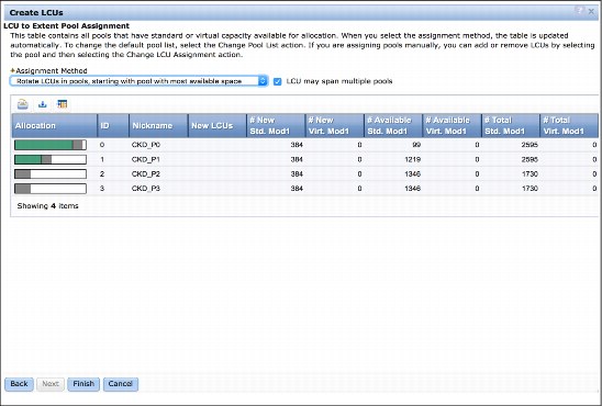
Figure 6-22 LCU to Extent Pool Assignment panel
13. We leave the default values and click Finish. The Create LCUs Verification panel displays, as shown in Figure 6-23.

Figure 6-23 Create LCU Verification panel
14. We select Create All. The GUI system creates the LCUs in increasing LCU ID order, All LCUs, and their volumes at the same time, as shown in Figure 6-24.

Figure 6-24 Creation in progress
6.8 Configuring parallel access volumes
Parallel Access Volumes (PAVs) are used to improve the DS8000 performance during large I/O transactions. It is recommend that the necessary PAV aliases are created at configuration time.
|
Note: This step can be done now or later during the ServerPac preparation phase. Ensure that there is enough volume space available for PAV configuration later.
|
We complete the following steps to configure PAVs:
1. From the CKD LCUs and Volumes main page, we select Volumes → CKD LCUs and Volumes. Then, we select Manage LCUs. The manage LCU panel is displayed, as shown in Figure 6-25.

Figure 6-25 Manage LCUs panel

Figure 6-26 Manage LCUs panel
The Add Alias panel displays, as shown in Figure 6-27.

Figure 6-27 Add Alias panel
3. We select the planned Alias volume number, leave the starting address and order as default, and click Next. The Add Aliases Verification panel displays, as shown in Figure 6-28.

Figure 6-28 Add Aliases Verification panel

Figure 6-29 Alias initialization in progress
5. We repeat these steps until all of the LCUs include defined aliases.
6.9 Downloading and filing the configuration file from GUI
We complete the following steps to download and file the configuration file from the GUI:
1. We download the extent pool configuration spreadsheet file, as shown in Figure 6-30.

Figure 6-30 Download extent pool spread sheet
2. A file that is named ExtentPools_IbmStoragePlex-< is created. We save the file, rename it to a .txt file, and open the file by using our spreadsheet tool. The extent pools configuration is displayed, as shown in Figure 6-31.

Figure 6-31 Extent Pools spreadsheet

Figure 6-32 Download LCUs spreadsheet
4. A file that is named AvailableLcus_IbmStoragePlex-< is created. We save the file, rename it to a .txt file, and open the file by using our spreadsheet tool. The extent pools configuration is displayed, as shown in Figure 6-33.

Figure 6-33 LCU spreadsheet

Figure 6-34 Download spreadsheet
6. A file that is named Volumes_IbmStoragePlex-< is created. We save the file, rename it to a .txt file, and open the file by using our spreadsheet tool. The extent pools configuration is displayed, which includes all of the volume information that is defined in this LCU.
7. Repeat Step 6 for all of the LCUs so that all volume configuration spreadsheets are filed, as shown in Figure 6-35.

Figure 6-35 Volumes spreadsheets
We now move on to Phase 4.
..................Content has been hidden....................
You can't read the all page of ebook, please click here login for view all page.