2
Material Flow and Facilities Layout
Several productivity metrics, such as throughput and lead time, are directly affected by the where and how the processing and storage resources are located in a factory. In this chapter, different types of industrial processes and plant layouts are discussed.
Plant layout (changes in resource or even factory location) is an activity that all companies are forced to deal with sooner or later. These situations occur because of technology innovations, increases in demand, and certain other productivity reasons. Therefore, it is important to be familiar with the methodologies used to carry out these kinds of studies.
Cellular layouts—where labor and machines are grouped in cells— will be presented in this chapter because they are becoming increasingly important and also because they require specific methodologies. Cellular layouts will be explained in greater depth in Chap. 3.
LAYOUT IMPROVEMENTS
Factory layout improvements typically occur more than one time during a factory's life. The study of plant layouts seeks the optimal location for all the production resources. At the same time, the study tries to ensure that the economic impact of the project on the enterprise will be as positive as possible. Lastly, the new plant layout must be as safe as possible and satisfactory for the employees.
With all these restrictions, it seems obvious that the optimal solution could be unreachable. In reality, the ideal plant layout can be reached if and only if a commitment between all the aspects previously mentioned is achieved.
Signs and Reasons for a Need to Change the Layout
The signs and reasons to propose a change in a plant layout are varied, but some of these reasons appear more frequently and therefore are described below.
Location Change. There are multiple reasons to suggest a change of location of a factory. Some companies were founded many years ago in locations that have become small or antiquated. Some companies are located in an urbanized area where a factory extension is impossible.
The starting point for a new plant layout is also different if the company chooses a new location and carries out new building construction or if the new location is already built. Today, new building constructions allow for an ideal layout because, with a few exceptions, building functionality is the principal focus in the building's design. As a result, the factory surface is better utilized.
Purchase of New Equipment. New needs and technology improvements form the basis of machinery purchase. Finding the best location for the purchased equipment can become a critical issue in making a “system” perform as intended.
Newly purchased incremental equipment generally is placed in the first free space available. In some cases, when there is no free factory space, it is necessary to move machines to create space. In other cases, a global layout project is outlined, and the new machine is located in a place that promotes system efficiency. These equipment movements can be crucial in production effectiveness as well as in the consideration of future equipment purchases.
Problems with the Materials Flow. This problem generally derives from the problem presented previously: placing new equipment in the first available corner of a plant. As a result, the initial setup costs decrease, but other problems arise later. Depending on the operation that the new machine carries out and its relative situation with respect to the preceding and next machine (in terms of process flow), the materials flow can be adversely affected on a larger or smaller scale.
It is important to remember that equipment setup is done only once, whereas materials flow is a continuous process. The analysis of this materials flow justifies the investment in time and money needed in the new equipment incorporation study and in most cases can be demonstrated economically. It is recommended to analyze an optimal location for the new equipment that will improve materials flow even before buying the equipment.
High Work-in-Process (WIP) Most company situations vary over time, so what may have been a good policy or layout in a given period of time may not produce good results forever. A measure or good indicator of change in a company is the amount of partially completed products (work-in-process). It is important not to confuse a temporary situation caused by a momentary increase in demand with a permanent and untenable situation.
It is only in the case where product mix and batch size changes occur that a company proceeds to a detailed layout analysis. Slow changes in product variability can hide the negative effects of the excessive work-in-process (WIP) caused by engineering and demand changes in the manufactured products.
THEORETICAL BASIS
One-Piece Flow
Before we start explaining the layout analysis tools, it is important to clarify the definition of production and transfer batch even though both sizes normally are the same:
- Production batch refers to the number of products included in a customer order.
- Transfer batch is defined as the number of units that flow from one machine to the next machine. This is also referred to as a unit load.
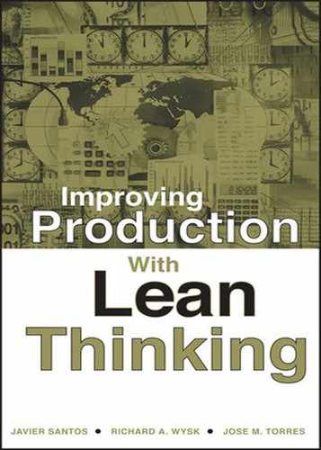
The work-in-process decreases according to the reduction in transfer batch size, as shown in Fig. 2.1.
In the first case, the transfer batch is equal to the production batch, whereas in the second case, the number of pieces that flow is one-third the production batch. The advantages of reducing the transfer batch are However, reduction in the transfer batch increases the materials handling between sections in the same proportion as the batch gets decreased.
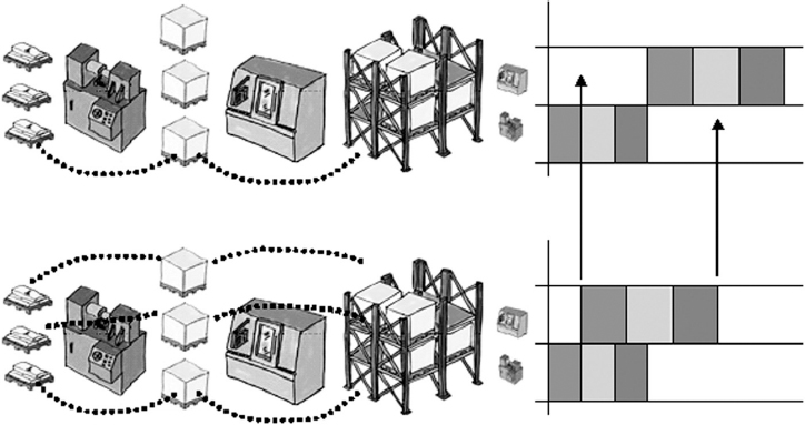
Figure 2.1. Difference between production batch and transfer batch.
- Production feedback is faster. As a result, information about the quality of a product is received sooner, and the reaction to prevent rejection of the whole batch is quicker.
- The lead time decreases. This was shown in Fig. 2.1.
The ideal transfer lot size, and therefore, the ideal flow between working areas, is what is called a continuous one-piece flow. This definition outlines one problem: If one of the production areas stops, the whole production plant will stop owing to the absence of material. This problem forces the number of pieces or work-in-process to be established beforehand. Normally, a container size is considered one-piece flow. For example, a “1000-screws flow” can be used as one-piece flow.
One-piece flow eliminates most of the signs and reasons for a need to change the layout outlined in the preceding section, and it is one of the just-in-time (JIT) tools (Fig. 2.2).
To come closer to an ideal one-piece flow, the material flow between both equipment and workstations has to be minimized or eliminated (directly linking process activities). If this is not possible, then the machines should be located as close together as possible. The bottom line is that in order to improve the material flow, it is typically necessary to analyze and change the company's layout.

Figure 2.2. Location of one-piece flow in JIT schema.
Main Types of Industrial Companies
In the market there exists a multitude of different products: food, cars, computers, bricks, cement, ships, etc. Each product has a specific manufacturing process. The study of all these processes would require a heavy investment in time if they are not grouped by similarities.
The manufacturing processes of a car and a washing machine are similar, and they could be analyzed in the same manner. They can be considered “similar products.” In the same way, the manufacturing processes of yogurt and soap also can be studied together. However, no one would eat a conditioner bottle for dessert or wash their clothes with a yogurt shake.
Product grouping allows for the application of the same principles and tools to seemingly different companies, basing the groupings on the types of production facilities the companies use. As a result, all companies considered process industry have similar plant layout functionality (yogurt and soap production belong to this kind of industry).
Industrial companies, as well as the economy, can be grouped into four sectors: primary, secondary, tertiary and service sector. The primary sector and the service sector will not be considered in this book. Study will be centered on the secondary sector (process industry and consumption industry), as well as on the tertiary sector (production and assembly factories).
Process Industry. Several industries are process-focused industries, where manufacture of the product dictates the equipment and product flow. Included in this type of manufacturing are paper, wood, cement, painting, and fabrics manufacturers.
Some factories that produce consumption goods (e.g., beverages), although not properly considered part of the process industry, also will be grouped into this type because the manufacturing process is configured very similarly, although, logically, the hygiene measures will be much higher. Consumption goods are all food products such as yogurts, ice creams, and drinks, as well as pharmaceutical and cleaning products.
The typical process industry, as shown in Fig. 2.3, has four main steps:
- Raw materials preparation. The main raw materials usually are received in bulk and are stored in large warehouses or silos. The product mixing (or formula preparation) is carried out in hoppers, blenders, or smaller deposits. The exact material quantities are obtained from an ingredients list and then completed using scales and measures for the specific formulas for each article.
- Treatment. Depending on the product type or its specifications, treatment (or processing) is carried out through different operations, such as filtering, drying, sieving, etc.
- Finishing. Metals, for example, can lose some properties during the treatment process; therefore, it is necessary to restore them. In other cases, superficial treatments such polishing or painting are applied to obtain the final aspect of the product.
- Bottling or packaging. Finished products will go through the bottling or packing lines depending on their needs. This is the case for either chips or wine. Concrete, for example, is dumped in trucks that will transport it to the corresponding building or construction area. A product such as soap is packed in packages or bags of different sizes.

Figure 2.3. Example of a process industry.
It is important to clarify that some companies will have their own nuances, although they will be studied in the same grouping. For example, in a yogurt manufacturing company, after the various yogurts are packed, they must be fermented, whereas in a candy factory, the final products simply are stored.
Assembly Companies. Most of the products that are used daily (e.g., cars, televisions, microwaves, etc.) are manufactured in companies that exclusively assemble final products, buying most of the assembly components (Fig. 2.4).
These companies have assembly lines where the products or families of products are produced. Their components are purchased from external companies because these companies are responsible solely for the assembly. In some cases, e.g., in automobile or electrical appliance companies, some processing operations are also carried out within the factory (e.g., sheet cutting, welding, plastic injection molding, or painting). These are isolated operations performed by these companies because they are not profitable to subcontract.
Manufacturing Companies. Companies that manufacture component parts do not belong to any of the preceding groups. These companies are called manufacturing companies and are known for processes such as forges, plastic injection machines, presses, computer numerical control (CNC) machines, etc.

Figure 2.4. Motorbike assembly line.
Factory layout for manufacturing companies depends on the product type and volume to be manufactured. Later on in this chapter this type 8 layout will be analyzed in more detail. Figure 2.5 presents a tradition process layout example of a manufacturing company that specializes in the production of component parts.
Layout Types
There are numerous classifications of industries based on layout. We will use four basic layout groupings or classifications. The grouping is primarily the result of the materials flow in the production plant.
- Fixed-position layout
- Process layout
- Product layout
- Cellular or combination layout
Fixed-Position Layout. In this type of layout, the product does not move throughout the production process; the needed resources move (Fig. 2.6). This layout is used in the manufacture of products that are difficult to move (e.g., ships, buildings, trains, etc.) or in products with short or immediate needs (e.g., milling center, presses, etc.).

Figure 2.5. Example of a manufacturing company.

Figure 2.6. Fixed-position layout.
Historically this layout also was used for car production, although today the way automobiles are manufactured has changed drastically.
Process Layout. In this type of layout, machines are grouped into departments or stations according to the operations they perform. For example, presses are grouped in the pressing department (Fig. 2.7), and lathes form the lathe department.
This layout is used commonly in companies that manufacture by orders for specialty parts or components (one or a few of a kind). For example, a small job shop that makes unique dies or fixtures would use a process layout. Process layout typically is employed for a large variety of products that are made in very small batches (ones or twos).

Figure 2.7. Example of a process layout.
The advantages of a process layout are
- The system has the flexibility to produce almost any part that fits within the volumetric boundaries of the machines.
- An in-depth understanding of a specific process can be obtained.
- Some tooling and fixtures can be shared.
The disadvantages of process layout are
- The spaghetti flow is difficult to manage and control.
- There is usually a lot of inventory in front of each machine.
- Setup is usually expensive.
- Materials handling times are large.
- It is difficult to automate these types of systems.
Product Layout. In this type of layout, the machines are grouped according to the product manufacturing sequence (Fig. 2.8). Depending on the main activity of the production line, these layouts are called manufacturing or assembly lines. High volume component parts normally are produced using a product layout.
Assembly companies normally use this layout, especially in the automotive sector (Fig. 2.9). The layout change carried out by Henry Ford drastically reduced car production lead time. Today, some companies are able to manufacture an automobile every 40 seconds.
Product layout systems are used effectively for the economic production of high-volume goods. The advantages of these systems are
- Large batches can be produced inexpensively.
- Materials handling is minimal.
- In-process materials are minimized.

- It is easy to control these systems.
- Automation is more achievable and justifiable.
The disadvantages of these systems are
- They are inflexible, in that only one or very few products can be produced on them.
- Setup time for these systems is very large.
- Duplicate tooling is required to replace worn tooling so that maintenance can be minimized.
Cellular or Combination Layouts. Some companies cannot be classified exclusively as having one of the preceding layout types. The following paragraphs present some examples.
Large products manufacturing industries such as airplanes and presses have opted for modularization as the best way to simplify product assembly tasks. As a result, to assemble a large CNC machine, different modules are produced in different lines and assembled as subsets (Fig. 2.10).
Many companies, such as special screw manufacturers, owing to the demand, have been forced to change their layouts, dismantling sections and creating manufacturing cells (which will be discussed in Chap. 3). Cellular layout is a relatively new layout approach and will be treated separately from traditional layouts.
In some other companies interested in creating manufacturing cells, it is not possible to purchase or have available all the necessary machines for the high cost that this action implies. In this case, the company modifies the layout in order to allow all cells to share the critical resource. This is a combination layout between product and process layouts.

Figure 2.10. Modularization in machine production.
Other companies have a common first phase, organized according to the process layout, and different assembly lines to elaborate the final product. This distribution type is seen commonly in assembling companies, such as the appliances manufactures, with plastic injection and presses sections combined with assembly lines grouped by product families.
Characteristic of the Traditional Layouts
The three traditional layouts explained (fixed-position, process, and product layouts) have specific characteristics that make them suitable for some companies and not very appropriate for other types of companies. Table 2.1 presents a summary of the main ideas explained in preceding sections.
LAYOUT DESIGN METHODOLOGY
Six basic steps are necessary to design an acceptable solution for a layout problem. Although these steps are applicable to most layout problems, they are oriented mainly for a general layout analysis. If the study objective is more restricted, it is not necessary to apply all the steps.
TABLE 2.1. Main Characteristics of the Three Traditional Layouts

Step 1: Formulate the Problem
Although it seems trivial, it is extremely important to define what the main objective of the study is: Including a new machine? Modifying the existing building? etc.
Step 2: Analysis of the Problem
Analysis of the actual situation can be carried out in a systematic way. Richard Muther in his classical book, Practical Plant Layout, presented eight factors to consider for facilities layout. These factors will be described briefly in the tools section of this chapter.
Step 3: Search for Alternatives
Analysis of Muther's eight factors enables engineers to define the problem and align the solution properly to the problem. Nevertheless, it is important to take into account three practical principles.
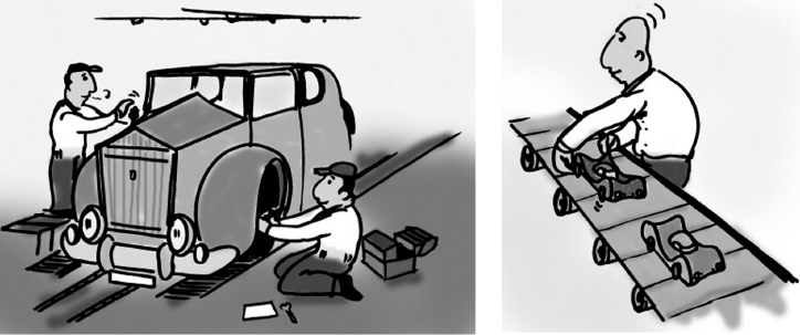
First the Whole and Then the Details. Both large layout changes and cellular layout design problems should be kept in mind, giving priority to the general area or total space shared and then to each one of the specific areas (Fig. 2.11). Layered planes are developed to characterize the situation. The layered planes help to illustrate the general flows between different departments.

Figure 2.11. First the whole and then the details.
First the Ideal Solution and Then the Practical One. It is important to realize from the very beginning of the project that the ideal solution is difficult to reach (Fig. 2.12). However, in many cases good solutions, very near to the ideal solution, can be developed more easily.
Realizing that the ideal solution requires infinite knowledge, a more particle approach is more worthwhile so as not to waste time and effort analyzing the problem in depth.
Brainstorming. The first step in the layout process is the creation of ideas, where several possible solutions are generated, with not a single solution being rejected. The brainstorming methodology recommends considering all the ideas the development team proposes without criticizing them. Being critical at this point can hinder the creativity process, and sometimes ideas that appear “far out” at first become realistic solutions with small changes. It would not be the first time that brilliant solutions are obtained from a seemingly crazy idea.
It is also important to remember that factories have a third poorly used dimension: the height or overhead space. Today, a significant number of companies use overhead space as temporary storage. As a result, the useful area of the plant is increased.
Figure 2.12. First the ideal solution and then the practical one.
Step 4: Choose the Right Solution
The objective of this step is to choose the solution that fits best among the solutions that have been proposed in the preceding step. Each one of the solutions should be evaluated according to a specific set of criteria.
A simply way of evaluating these possible solutions consists of ranking each alternative from 0 to 10 according to established criteria. The solution that obtains the best overall ranking will be the accepted one.
It is also very important to evaluate each alternative from an economic standpoint because frequently it is the “money factor” that determines which path is taken. The advantages and disadvantages of each solution should be specified, and always keep in mind that the simplest solution (between those which have received good rankings) will be the best choice. Many company folders contain plenty of completed and detailed layout studies that propose radical changes in the current configuration and that were never put into practice.
Step 5: Specification of the Solution
The accepted solution will need to be fully developed. Many details are not considered or defined in the preceding step because it is pointless to present a complete solution if it is not the definitive one.
This step is also useful to take care of safety measures in order to avoid possible future industrial accidents. Occupational Health and Safety Administration (OHSA) regulations and the Labor Risks Prevention Law provide guidelines for some minimum working solutions, e.g., minimum worker access. The adopted solution must be consistent with all laws and regulations. An example is shown in Fig. 2.13, where the situation presented on the left side of the figure should be avoided, migrating toward solutions such as the one presented on the right side.
Finally, it is necessary to itemize all details of the plan, request the corresponding budgets, and establish a schedule for implementation of the solution. It is also important to demonstrate quantitatively that the outlined solution will provide benefits when compared with the current situation.

Figure 2.13. Labor safety is a must in the outlined layout.
Step 6: Design Cycle
The design cycle includes planning for modifications that arise because of problems that appear while adopting a solution: budget deviations and/or problems in plant installations (electric or pneumatic lines).
At the end of the design process, the plant should work more efficiently. It is always worthwhile to check to see if the adopted solution works as expected.
TOOLS FOR LAYOUT STUDY
Muther's Eight Factors
By analyzing the following eight factors, it is possible to determine the main layout restrictions and requirements that a new layout alternative has in order to choose the best layout from a set of proposed solutions.
Material Factor. The material factor does not cover study of the materials used to manufacture the product, although the name might imply that it should. The purpose of this factor is to become familiar with the different production steps needed to manufacture the article and to analyze how the material is transformed from raw material to a final product.
The product sequence of operations should be studied without considering the relative location of each process in the factory. For example, to manufacture a screwdriver, the fist step consists of transforming a steel bar into the screwdriver bar with the right tip. The handle then would be created using an injection-molding process for a plastic handle, with the two pieces then being assembled. This factor helps you to understand the company technology and to know the company's range of products.
Machinery Factor. The second factor analyzes the machine types and the existing number of machines on the factory floor. It is important to take note of the number of each type and their principal dimensions in case this becomes a critical constraint. This machinery factor is shown in Fig. 2.14.
It is also necessary to analyze the operating conditions, such as vibration, temperature, etc., so as to avoid putting incompatible machines together. For example, a heavy sheet metal press and a precision coordinate measurement machine are not very compatible.
Labor Factor. The staff of the production department should be counted, from machine operators to section heads. In addition, materials handling and maintenance operator input is important.
To facilitate study of this factor, we recommend using worker-machine diagrams (a tool that will be explained in Chapter 5). This tool allows you to discover the operations that workers carry out on the machines and the relative disposition of the elements in the work area so as to simplify worker tasks.
Movement Factor. The movement factor analyzes the materials flow between work centers. This flow does not add value to the product, and as a consequence, as much handling as possible should be eliminated. Logically, completely eliminating movement is an ideal, but most often it is feasible to eliminate certain handling components to obtain a better solution. There are mainly two tools to analyze movement between machines: the flow-process chart and the transfer matrix.
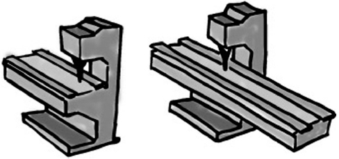
Figure 2.14. Considering machine dimensions.
Flow-Process Chart. A flow-process chart represents, in a graphic way, the path and the actions carried out on a product. Five standard symbols are used to show all the alternatives (Fig. 2.15). Also, it is possible to combine two or more of these actions, creating two or more new symbols.
The circle symbol represents an operation, the arrow symbol represents a transport, the square represents an inspection, the reversed triangle represents a storage, and the letter D represents a wait or delay. The difference between the last two symbols is that, in the first case, it is necessary to remove the product from a warehouse or inventory location after storage.
Using these symbols as tools, movement improvements can be envisioned and advantages quantified when a modification is presented, as shown in Fig. 2.16.
Transfer Matrix. A transfer matrix is a matrix representation of the work flow in a production plant. The matrix shows the fraction of work that flows from one section to all the others, including the raw materials and final product warehouses (Fig. 2.17).
Preparation of a transfer matrix is not complicated. The matrix considers the total amount of product that enters a work center, and the fraction moving to other work centers is calculated. This is distributed fractionally among the other sections; therefore, all the rows of the matrix should sum to 1.

Figure 2.15. Standard symbols on a flow-process chart.

Figure 2.16. Quantification of movement by means of the flow-process chart.
For example, in Fig. 2.17 it can be seen that half the work (50 percent) that enters M1 is sent to M2, 30 percent to M3, 10 percent to M4, and the last 10 percent to M5.
The matrix shows the volumes of different products that flow between work centers, but it does not indicate how heavy they are or their size. Therefore, the information in the matrix is not enough to make a fully informed decision about the convenience of locating two work centers adjacent to each other.
As a result, it is possible to use the same matrix concept but with another perspective, keeping in mind other factors such as the transferred weight or the number of routes executed. These matrixes will help to clarify the decision of the relative locations of departments in the factory plant.

Figure 2.17. Examples of transfer matrices.
Wait Factor. This factor covers study of the three main warehouses: raw materials, work-in-process, and final product. The objective of the wait factor is to determine the required space in each of the warehouses. Muther recommends in-depth analysis of the required space for each product. It normally happens that, owing to the magnitude of the warehouse study, a specific layout project must be outlined. Because the warehouse layout is closely related to its management (planning and control), it will not be studied in this book.
Service Factor. The service factor is used to analyze two different characteristics:
- Study of environmental workspace conditions (i.e., brightness, noises, smells, minimum working space) in order to decide what the acceptable parameters are with respect the OHSA regulations and the Labor Risks Prevention Law.
- Related with the preceding characteristic, the working conditions are analyzed with emphasis on the plant service staff. Plant services are mainly quality, logistics, and maintenance. Minimum maneuver space for forklift trucks or other special equipment used in these services is a typical factor.
Building Factor. The building factor analyzes the actual useful surface of the building. This factor takes into account the plant shape, the columns, the window situation for ventilation, and areas of possible extension. In many cases the surface area covered by gantry cranes limits the number of layout alternatives because in many cases these resources must overlap, and they cannot be moved easily.
Change Factor. Regrettably, the proposed layout will not be valid forever. Neither is it the goal of this factor to leave the company ready for any future change because the future is usually unknown.
The change factor is intended to observe, from a critical point of view, the adopted solution. For example, if the new raw materials warehouse has been designed without free space, it is very probable that the layout will have to be reconsidered in the near future if demand grows. As a consequence, the work already done will be of little value.
Application of this factor is without a doubt the most difficult part of the study. It is necessary to ask for future company plans (e.g., increases in the number of references, market target changes, etc.) with the purpose of extending the usefulness of the proposed layout for as long as possible.
SUMMARY
This chapter has demonstrated how materials flow can be improved significantly by means of layout analysis. In these kinds of improvement projects, study of the current situation allows one to identify constraints that reduce the number of possible alternatives to be considered. The proposed improvements will reduce the materials flow, allowing the company to raise the one-piece flow proposed by the lean manufacturing philosophy.
RECOMMENDED READINGS
Richard Muther, Practical Plant Layout. New York: McGraw-Hill, 1956.
Kjell B. Zandin and Harold B. Maynard, Maynard's Industrial Engineering Handbook, 5th ed. New York: McGraw-Hill, 2001.