Upon completion of this chapter, you should be able to
Explain what is meant by structured programming.
Identify hierarchy charts and explain their purpose in top-down programming.
Explain how flowcharts, pseudocode, and hierarchy charts are used as program design tools.
Identify the four logical control structures used in structured programming.
In the early days of programming, students learning to program believed that mastering the rules of a programming language was all that was needed to write well-designed programs. Often, instruction formats and coding rules necessary for writing programs were taught without ever fully explaining the way programs are actually designed. It is, of course, true that you must learn programming rules, or syntax, before instructions can be written. Unfortunately, however, knowledge of a programming language's rules will not guarantee that programs will be designed properly. That is, it is possible for a program to be written correctly without any syntax errors, and yet the entire set of procedures might be poorly designed so that they do not work properly or efficiently. In addition to learning syntax, then, software developers must learn how to design a program so that it functions effectively as an integrated whole. We define the term program design to mean the development of a program so that its elements fit together logically and effectively in an integrated way. Thus, software developers must be familiar with the techniques used to structure programs as well as the programming or syntax rules.
Learning syntax, then, is only one step in the process of developing programs. The syntax you learn is language-specific, meaning that each programming language has its own particular rules. But the techniques for developing well-designed programs are applicable to all languages. That is, the logical control structures for designing a COBOL program are very similar to those in other languages. Once you know how to design programs efficiently and effectively, it becomes much easier to learn the syntax rules of another language.
In this chapter, the focus is on the logical control structures used to design a program. We begin by showing you general concepts used to construct or design a program so that you can create structures that are easy to understand, debug, maintain, and modify. Then, we apply these structured programming techniques to COBOL/400.
Each well-designed unit or program segment should be written as an independent module and specified in a hierarchical order. The main module of a top-down program is written first, with the secondary modules initially sketched out, and the details filled in later, after the structure has been clearly described. The coding of modules in a hierarchical manner is called top-down programming. Only after the organization of the program has been determined will the software developer write the specific instructions in each module.
Top-down programming is analogous to the technique of outlining a paper before it is actually written. First, each topic in a paper is sketched out until the organization is clear; only then are the details filled in. Similarly, the main module of a top-down program is written first, with the details for each subordinate module left for later.
In COBOL, each well-defined unit or program segment, called a subroutine, should be written as a module and executed with a PERFORM. This technique allows control to pass temporarily from one module or subroutine to another and then return to the original one from which it was executed. Subordinate modules can be written after the main structure or overall logic has been mapped out.
Well-designed programs have a logical structure, where the order in which instructions are executed is standardized. Each set of instructions that performs a specific function is defined in a module or program segment. A module is also called a routine or, in COBOL, a paragraph. It consists of a series of related statements. Each module is executed in its entirety from specific places in a program. In our case problem illustrated earlier, the program contains two modules or paragraphs, one labeled 000-MAIN-MODULE and one labeled 200-PROCESS-RECORD-RTN.
With well-designed structured programs, each set of instructions that perform a specific function is represented by a logical control structure. Logical control structures refer to the different ways in which instructions may be executed. Most instructions are executed in the sequence in which they appear in the program. Other times, however, different sequences of instructions are executed depending on the outcome of a test between two fields. Still other times, a series of instructions might be executed repeatedly from different points in a program.
Well-designed programs are systematically planned before they are written. The planning process minimizes logic errors by helping the software developer determine how all instructions will interrelate when the program is actually written. Planning tools that help software developers map out program logic consist of
Hierarchy charts.
Flowcharts.
Pseudocode.
Just as architects prepare blueprints before buildings are constructed, so, too, should software developers use planning tools before a program is written. The
planning process minimizes logic errors by helping the software developer determine how all instructions will interrelate when the program is actually written.
Flowcharts and pseudocode are planning tools used to depict the instructions and logical control structures that are used when a program is actually written. They help plan a program so that the instructions are implemented properly and efficiently in a standardized manner. Both of these planning tools are language independent. That is, they help plan the logic to be used in any program regardless of the language used to write the program. Thus, they afford us the benefit of illustrating the control structures in a general or theoretical way, without being dependent on any specific language rules. Once you understand how to plan the logical control structure of a program using pseudocode and flowcharts, you need only learn the specific language's rules to write the program. Typically, a software developer uses either a flowchart or pseudocode to map out program logic.
The overall relationship among major and minor components of a well-designed program is accomplished using hierarchy charts. This tool, however, is not intended to map out specific logical control structures but simply to illustrate the top-down relationships among the modules in a program.
Thus, before writing a program you need to plan the logic in two ways.
With a hierarchy chart, illustrate how the modules are related to one another in a top-down fashion.
With a flowchart or pseudocode, illustrate the logical structure, that is, how instructions are actually executed.
The planning tool best used for illustrating a top-down approach to a program is a hierarchy or structure chart. A hierarchy or structure chart provides a graphic method for segmenting a program into modules. Its main purpose is to provide a visual or graphic overview of the relationships among modules in a program. With a hierarchy chart, an entire set of procedures can be segmented into a series of related tasks.
The concept of top-down or hierarchical programming is accomplished by coding main modules first, with minor ones detailed later. These modules are said to be written hierarchically.
A main module is subdivided into its components, which are considered subordinate modules. Think of a top-down design as an outline of a paper. Begin by sketching the main subject areas and components, and then focus on the minor details only after the main organization has been defined.
Note the following about hierarchy charts:
A hierarchy chart represents program modules as rectangular boxes and illustrates the interrelationships among these modules with connected lines.
A module is a well-defined program segment that performs a specific function. A module may be an initialization routine, heading routine, an error-checking routine, termination routine, and so forth.
The following example illustrates the relationships of modules in a hierarchy chart. In practice, we would use meaningful names for modules. The identifiers 000-A through 230-H are used here as paragraph-names for the sake of brevity and to highlight the concepts being illustrated.
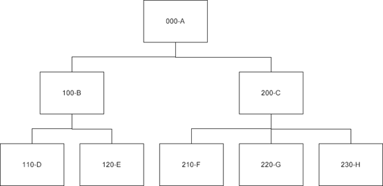
The paragraph names 000-A through 230-H represent paragraph-names that are executed with the use of PERFORM statements as follows:
000-A.
.
.
.
PERFORM 100-B.
PERFORM 200-C.
.
.
.
100-B.
.
.
.
PERFORM 110-D.
.
.
.
PERFORM 120-E.
.
.
.
200-C.
.
.
.
PERFORM 210-F.
.
.
.
PERFORM 220-G.
.
.
.
PERFORM 230-H.
The hierarchy chart only illustrates modules executed from other modules. Unlike a flowchart or pseudocode, actual instructions are not depicted. Each block or box in a hierarchy chart represents a module. If a module calls for another module, this is depicted in a separate box. Consider the following section of the preceding hierarchy chart:
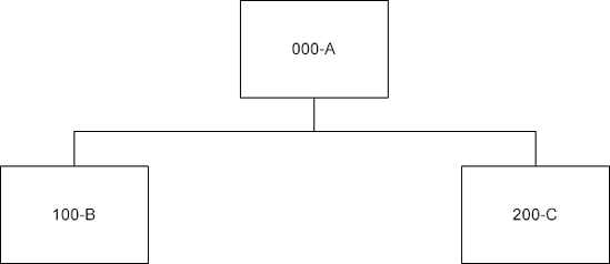
From this excerpt, we see that modules 100-B and 200-C are executed from module 000-A.
Note that a module that is executed by a PERFORM can have a PERFORM in it. Module 110-D, for example, is performed from Module 100-B, which is executed from the main module, Module 000-A.
Consider the following:

This example shows that Module 220-D is executed from both Module 100-B and Module 200-C. To highlight the fact that Module 220-D is executed from more than one point in the program, we use a broken line for the boxes labeled 220-D.
In summary, the hierarchy chart illustrates how modules relate to one another, which modules are subordinate to others, and whether or not a module is executed from more than one point in the program. This structure chart makes it easier to keep track of the logic in a program. Moreover, if a module must be modified at some later date, the hierarchy chart will tell you how the change might affect the entire program. It does not consider the actual instructions within each module, just the relationships among them. The actual sequence of instructions is depicted in a flowchart or pseudocode, which would supplement a hierarchy chart as a program planning tool.
Consider a program that calculates wages for each employee, where overtime is calculated as time-and-a-half. The program prints 50 lines on a page, after which a new page with headings is generated. The hierarchy chart for this pay-
roll program is illustrated in Figure 5.1. You can see that the hierarchy chart provides an overview of the relationships among modules. Modules with broken lines are performed from more than one point in the program.

Note that when a subordinate module, such as 210-COMPUTE-OT-WAGES-RTN, is executed in its entirety, control then returns to the next highest module, 200-PROCESS-RECORD-RTN in this instance. 200-PROCESS-RECORD-RTN is executed repeatedly until ARE-THERE-MORE-RECORDS = 'NO', at which time control returns to 000-MAIN-MODULE. Because logical control is depicted in this hierarchical fashion in a hierarchy or structure chart, it is referred to as a top-down tool.
In summary, then, a hierarchy chart has the following advantages:
It helps software developers and users see how modules interrelate.
It helps software developers debug and modify programs.
It helps software developers assess the efficiency of programs.
Thus, the hierarchy chart, like a pseudocode and flowchart, is both a design and documentation tool.
As previously noted, a module or set of related instructions is equivalent to a paragraph. We have been using module or paragraph-names such as 000-MAIN-MODULE and 200-PROCESS-RECORD-RTN without really reviewing why
those names were selected. Recall that paragraph-names can be a combination of letters, digits, and hyphens up to 30 characters.
We use a standard method for naming paragraphs in all programs. First, as previously noted, we choose a meaningful name, one that describes the module. Names such as MAIN-MODULE, PROCESS-RECORD-RTN, and TERMINATION-RTN are descriptive in that they provide the reader with some idea of the type of instructions within the module.
In our examples, we also use 100-, 200-, and so on as prefixes to these descriptive names. Module-names are given prefixes that provide information on their location. That is, module 000- precedes module 200-, which precedes module 210-, and so forth. You will find that in very large programs that require several pages for listing, this type of numbering makes it much easier to locate a module during debugging or program modification. The numeric prefixes we use begin with 000-, and then increase by intervals of 100. For the lower-level modules, they increase by 10. This convention is easy to follow and allows for possible insertions later on.
We have seen that top-down programs are developed with main units or modules planned and written first, followed by more detailed ones. Structure or hierarchy charts illustrate the relationships among these modules. Statements that together achieve a given task should be written as a module. Consider the following:
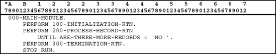
Simple PERFORMs are written so that a series of steps can be executed in a separate module. To execute a paragraph like 300-TERMINATION-RTN only once we write a simple PERFORM as follows:
000-MAIN-MODULE.
.
.
PERFORM 300-TERMINATION-RTN.
Instructions within 300-TERMINATION-RTN are executed once and control returns to the statement following the PERFORM in 000-MAIN-MODULE.
100-INITIALIZATION-RTN would OPEN all files, READ the first record, and perform any other operations required prior to the processing of data. These instructions could have been written directly in 000-MAIN-MODULE, but because they are really a related set of instructions we treat them as a separate unit. We encourage this type of modularity, especially for complex programs or when standard initializing procedures are required by an organization.
Similarly, 300-TERMINATION-RTN would CLOSE all files but might also include other procedures such as the printing of final totals. Here, again, such statements represent a unit and should be modularized.
Most software developers use initializing and end-of-job procedures as modules rather than including the individual instructions in the main module. In this way, the main module provides a bird's-eye view of the entire structure in
the program. This modularization eliminates the need to include detailed coding until after the structure has been fully developed.
Two useful tools for planning the logic to be used in a program are flowcharts and pseudocode. Both of these planning tools are language-independent. That is, they help plan the logic to be used in any program regardless of the language in which the program will be written. Thus, they afford us the benefit of illustrating the control structures in a general or theoretical way, without being dependent on any specific language rules.
A flowchart is a diagram or pictorial representation of the instructions and logical control structures that will be used in a program. Similarly, pseudocode is a set of statements that specifies the instructions and logical control structures that will be used in a program.
Flowcharts and pseudocode are planning tools that should be prepared before the program specifications are written. They map out and then verify the logic to be incorporated in the program. Usually a program is planned with either a flowchart or pseudocode.
The following symbols are the ones most frequently used in program flowcharts:


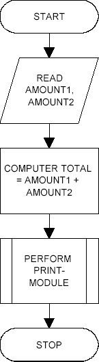
Consider the following simple flowchart:

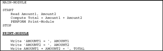
This sequence of instructions is called a module. The beginning and end of a module are designated with terminal symbols that are labeled START and STOP respectively. The first instruction or statement is READ AMOUNT1, AMOUNT2 meaning, "read into storage a value for a field called AMOUNT1 and a value for a field called AMOUNT2." This is an input operation and is specified in an input/output or I/O symbol. The words used in the symbol need not be precisely as written. For example, INPUT AMOUNT1, AMOUNT2 would also be acceptable. Because a flowchart is a planning tool that is language-independent, you need not follow any language's specific syntax rules when drawing the flowchart.
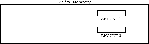
When written and executed, the first instruction in the sequence will read into primary storage or main memory a value for AMOUNT1 and a value for AMOUNT2, where AMOUNT1 and AMOUNT2 are field-names or symbolic addresses.
The next instruction in the illustrated flowchart module computes TOTAL as the sum of AMOUNT1 and AMOUNT2; it is described in a processing symbol. All arithmetic operations are considered processing operations.
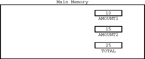
In the program, AMOUNT1 and AMOUNT2 are added and the result placed in a field or symbolic storage address called TOTAL. Suppose 10 is entered as input for AMOUNT1 and 15 is entered as input for AMOUNT2. Main memory would have the following contents in the fields or symbolic storage addresses defined in this program:
The next instruction, WRITE TOTAL, is an output operation that will print the contents of the field called TOTAL. It is also specified in an I/O symbol.
The flowchart is read from top to bottom. Since there is no need to repeat instructions or to test for any conditions, this simple flowchart indicates that two numbers are read, added together, and the sum printed.
Suppose we wish to print not only TOTAL but also a series of headings. We can include each of these processing steps in our module, but that would mean our module would include numerous details. It would be better to include a predefined process in which we say PERFORM PRINT-MODULE; in this way, the print details could be left to the subordinate module called PRINT-MODULE. The following illustrates how we would draw a flowchart symbol to indicate that a predefined process called PRINT-MODULE is to be executed at a specific point:
In a COBOL program we can execute such a PRINT-MODULE by coding PERFORM PRINT-MODULE. PRINT-MODULE, then, would be defined in detail in a separate sequence.

The term PRINT-MODULE itself can identify the entire sequence, as in the preceding, or replace the word ENTRY in the terminal symbol.
Flowcharts have been used as planning tools for many decades. Structured programming, on the other hand, is a more recently developed technique. When structured programming became the preferred method for designing programs, flowchart symbols had to be modified to accurately depict a structured design. Many software developers and managers found that these modifications made flowcharts difficult to use as a planning tool. As a result, flowcharts are less widely used in many organizations, having been replaced by other tools that more clearly depict the logic in a structured program. Pseudocode is one such tool.
Pseudocode has been designed specifically for representing the logic in a structured program. No symbols are used as in a flowchart; rather, a series of logical control terms defines the structure. A line or group of lines of pseudocode denotes each processing or input/output step. As with flowcharts, the pseudocode need not indicate all the processing details; abbreviations are permissible. Also as with flowcharts, you need not follow any language rules when using pseudocode; it is a language-independent tool.
The following are pseudocode rules:
Pseudocode is written and read from top to bottom.
The logical control structure of pseudocode is defined with the use of key terms such as PERFORM . . . ENDPERFORM, IF-THEN-ELSE . . . ENDIF, and CASE . . . ENDCASE.
The operations to be executed within a PERFORM, IF-THEN-ELSE, or CASE can be written in sequence or in a separate module.
Like a flowchart, pseudocode is read in sequence unless a logical control structure is encountered. In the preceding section, we illustrated a flowchart for a program that reads in two numbers, adds them, and prints the total. The pseudocode for this sequence is

As with flowcharts, the START and STOP delineate the beginning and ending points of the program module. Words such as "Read Amount1, Amount2" are used to convey a message and need not be written precisely as shown. Thus, "Input Amount1, Amount2" would be acceptable. Similarly, "Let Total = Amount1 + Amount2" could be used rather than "Compute Total = Amount1 + Amount2" for the second instruction.
To illustrate the performing of a PRINT-MODULE as we did with a flowchart, we would have the following in pseudocode:
This is called an in-line PERFORM since all instructions appear directly after the word PERFORM.
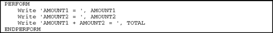
In place of the predefined process PERFORM PRINT-MODULE that appeared in our flowchart, we can write a structured pseudocode that would include the following:
When you design your own programs, we recommend that you begin by drawing a flowchart or pseudocode and a hierarchy chart. You will find that these tools are extremely helpful in mapping out the logic to be used in your program. Although our early programs have relatively simple logical control constructs, the use of program planning tools will be extremely helpful later on when you write more complex programs. When a flowchart or pseudocode is written correctly, it is relatively easy to convert it to a program, assuming you know the syntax or rules of the programming language. You may also find that
these planning tools will help you spot potential logic errors that, if specified in a program, may produce erroneous results.
Structured programs use logical control structures to specify the order in which instructions are executed. These structures are the same for all languages. Thus, if you learn how to use them in COBOL, it will make learning to program in other languages much easier. The four logical control structures are
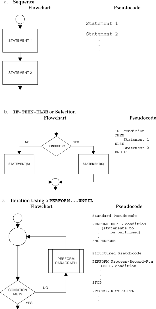
When instructions are to be processed step-by-step in some fixed way, we use a sequence to depict the logic. That is, when instructions are executed in order regardless of any existing condition, we write them as a sequence. As another example, the following instructions would represent a sequence where the set of instructions is executed in the order in which they appear, that is, top to bottom. The ellipses (dots) within each symbol just mean that each statement has other components.

Selection is a logical control construct that executes instructions depending on the existence of a condition. It is sometimes called an IF-THEN-ELSE logical control structure.
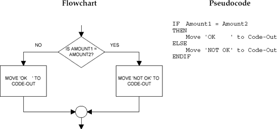
Consider a situation where you wish to execute different instructions depending on the contents of a field called AMOUNT. The flowchart format for an IF-THEN-ELSE logical control structure along with the specific flowchart excerpt for this example are

If the condition is true (or exists), we execute the statement or statements on the right. If the condition does not exist (or is false), we execute the statement or statements on the left. In either case, the flow returns to the circle or connector, where the next instruction, in sequence, is executed.
The general pseudocode format for the IF-THEN-ELSE logical control structure along with the specific pseudocode for the preceding example are
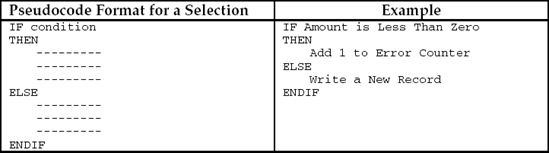
In pseudocode, the word IF is followed by the condition to be tested, the word THEN is followed by the statements to be executed if the condition exists, the word ELSE is followed by the statements to be executed if the condition does not exist, and the word ENDIF ends the selection process. All entries except the words IF, THEN, ELSE, and ENDIF are indented on a separate line so that the structure of the selection is highlighted. We capitalize only the logical control terms IF, THEN, ELSE, and ENDIF, which also helps to highlight the structure.
We will see later that a COBOL program can look just like pseudocode. That is, the word THEN may be used to indicate which statements to execute if the condition exists. Similarly, END-IF can be used to mark the end of the IF statement itself. Thus, the pseudocode for the preceding example with IF-THEN-ELSE-ENDIF resembles a COBOL program excerpt—the only difference is that the END-IF scope terminator, with a hyphen, is used with COBOL rather than the pseudocode delimiter ENDIF.
In our case problem, we illustrated a logical control structure referred to as the PERFORM . . . UNTIL. This instruction enables us to execute a series of steps from the main module repeatedly until a specific condition exists or is met. The structure that makes use of the PERFORM . . . UNTIL is called iteration. Iteration is a logical control structure used for specifying the repeated execution of a series of steps. Consider the following type of iteration:

This means that the module that we have called 200-PROCESS-RECORD-RTN is executed repeatedly until the field labeled ARE-THERE-MORE-RECORDS is equal to 'NO'. This type of iteration is flowcharted as

The flowchart symbol used to indicate a PERFORM is referred to as a predefined process. With a PERFORM . . . UNTIL, if the condition tested in the decision symbol is not met, the predefined process symbol is used to identify the named paragraph that is to be executed. The instructions in the paragraph identified within the predefined process symbol are defined or described in detail in a separate module. The flowchart indicates that we continue to execute the named module until the specified condition is met. In the example, the paragraph named 200-PROCESS-RECORD-RTN is executed repeatedly until the field called ARE-THERE-MORE-RECORDS has a value of 'NO'. When the condition is finally met, we continue with the next step in sequence after the PERFORM . . . UNTIL. This type of iteration is also referred to as a loop.
The paragraph named in the predefined process symbol would be flow-charted as a separate sequence. The following is an example of the relationship between two modules using a PERFORM . . . UNTIL:

The in-line or standard pseudocode for a PERFORM . . . UNTIL type of iteration is

The module or series of steps to be performed would be specified on the lines between the words PERFORM and ENDPERFORM. These instructions are indented to highlight the fact that they are part of a separate logical control structure.
The structured version of this pseudocode closely resembles modular COBOL. The structured pseudocode is

PERFORM . . . UNTIL is a type of iteration that is most commonly used for logical control structures in COBOL. The same type of structure is frequently called DO . . . WHILE in other languages. Here again, the words used to describe iteration are not as important as the concept itself.
Let us again consider the PERFORM . . . UNTIL in which a predefined process is executed as part of an iteration. Keep in mind that the module executed is under the control of the PERFORM and is executed repeatedly until a specified condition
exists or is true. The condition being tested must at some point be true for the PERFORM . . . UNTIL to terminate properly. Consider the following:
PERFORM 200-PROCESS-RECORD-RTN
UNTIL ARE-THERE-MORE-RECORDS = 'NO'
This means that the paragraph called 200-PROCESS-RECORD-RTN must contain an instruction that, at some point, causes the contents of the field ARE-THERE-MORE-RECORDS to be changed to 'NO'. If the field is never changed to 'NO', then 200-PROCESS-RECORD-RTN is executed repeatedly without any programmed termination. This error is called an endless loop or infinite loop. We avoid infinite loops by ensuring that the field being tested in the UNTIL clause of a PERFORM is changed within the paragraph or module that is being executed.
Consider the following flowchart excerpt:

If the instruction ADD 1 TO TOTAL were omitted from the 500-TOTAL-IT module, then the sequence of instructions at 500-TOTAL-IT would result in an infinite loop because TOTAL would never equal 10.
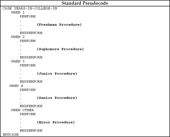
The case structure is a special logical control structure used when there are numerous paths to be followed depending on the contents of a given field. For example, if a coded field is equal to 1, we want to perform a print routine; if it is equal to 2, we want to perform a total routine, and so on. With the case structure, then, we wish to perform one of several possible procedures depending on some condition.
Suppose an input field called YEARS-IN-COLLEGE-IN is used to determine the type of processing to be performed. The procedure or module to be executed depends on the entry made by a user. This can be described with a flowchart as follows:
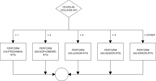
We use a case structure in place of a series of simple conditions. As we will see in later chapters, the best way to specify the case structure is by using the EVALUATE verb

The WHEN OTHER clause is executed when YEARS-IN-COLLEGE-IN is not 1, 2, 3, or 4.
Once a condition in an EVALUATE is met, there is no need for the program to test other conditions in the statement. Thus, after a condition in a WHEN is met and the corresponding imperative statements are executed, execution continues with the statement following END-EVALUATE. If additional valid values need to be added, it is a simple task to add the appropriate clauses.
With the use of the EVALUATE, you can perform different routines depending on the contents of a field. You can also determine if a field has invalid contents with the WHEN OTHER clause. In the preceding, we perform the appropriate procedure depending on the contents of the YEARS-IN-COLLEGE-IN field; if the code is invalid with a value other than 1, 2, 3, or 4 an error message would be printed.
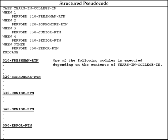
The standard and structured pseudocode for a case structure are
In general, we write COBOL programs with one clause per line.

Words and clauses can be separated with any number of blank spaces. Therefore, we can be as generous as we wish in our use of coding lines. Coding one clause per line makes programs easier to read and debug. If an error occurs, the compiler lists the erroneous line number. Having only one clause on each line helps to isolate the error.
In addition to coding one clause per line, we also indent clauses. Indentation makes programs easier to read. In general, we will indent four spaces on each line. Tabbing can be used with most source editors for indentation.

Sometimes we indent more than four spaces for the sake of alignment:

To align the words INPUT and OUTPUT and the file-names we indented more than four spaces on the second line.
Suppose we want to add 1 to TOTAL and read a record if AMOUNT1 = 100:
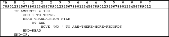
Notice the use of indentation here. We actually indent twice on the fourth line to help clarify that the AT END clause is part of a READ, which itself is part of an IF statement.
As you proceed through this book, you will see how indentation is used to clarify the logic. You should use this technique in your programs as well. Note, however, that indentation does not affect the program logic at all. It is simply a tool that helps people read the program.
Problem Definition
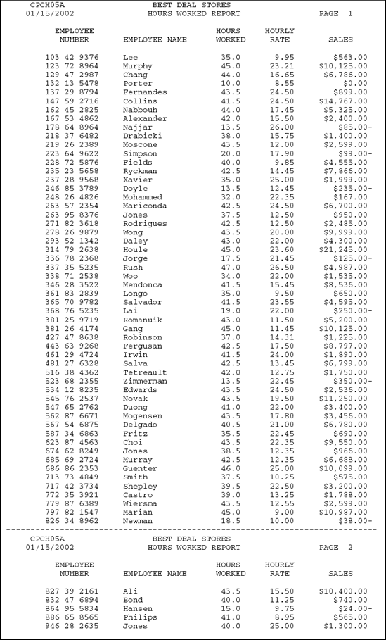
The Payroll Manager of the Best Deal Stores Company wants the Employee Hours Worked Report program to be written as a structured program. Modifying the Employee Hours Worked Report program illustrated in previous chapters will accomplish this.
The systems flowchart, hierarchy chart, input specifications for the Employee Pay File, Output Specifications showing the layout of the report to be
produced, and a flowchart of the program that will read the Employee Pay file and print the Employee Hours Worked Report are illustrated here:
Systems flowchart

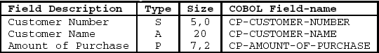
Record description layout for Employee Pay file — EMPPAYPF

Printer spacing chart for Employee Hours Worked Report

Hierarchy Chart

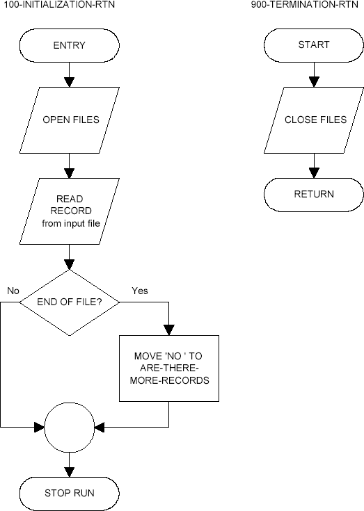
Flowchart for Structured Employee Hours Worked Report program


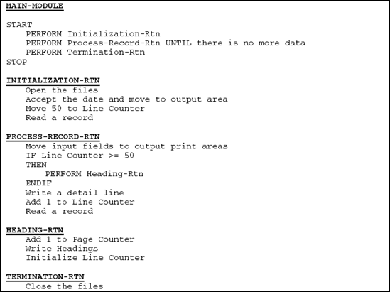
The following is the structured pseudocode for our case problem:
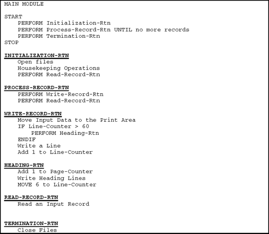
The actual words used in a pseudocode need not follow any specific rules. We can say "Housekeeping Operations" to mean any initializing steps, or we can say "Open Files." Similarly, we can say "PERFORM UNTIL no more records" or "PERFORM UNTIL ARE-THERE-MORE-RECORDS = 'NO'." As a rule, however, the logical control words such as PERFORM . . . ENDPERFORM are capitalized. This highlights the control structures in a pseudocode.
The degree of detail used in a pseudocode can vary. Only the logical control structures such as PERFORM . . . ENDPERFORM, IF . . . THEN . . . ELSE . . . ENDIF, and CASE . . . ENDCASE need to be precisely defined. The actual instructions may be abbreviated. For example, Move and Write instructions within a PERFORM . . . UNTIL structure might be abbreviated as "Process the data." You will find that the more detailed a pseudocode becomes, the closer it is to COBOL.
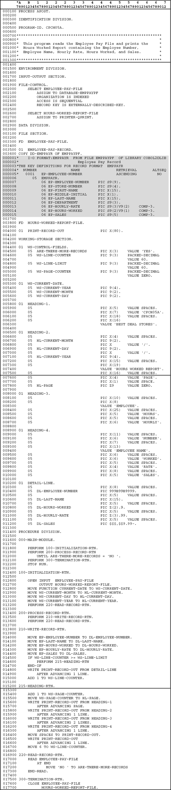
The program in Figure 5.2 produces the Employee Hours Worked report. The actual report is shown in Figure 5.3.
The 000-MAIN-MODULE has the following operations:

The first routine that is executed in 000-MAIN-MODULE is the 100-INITIALIZATION-RTN. This routine performs the following operations:
Following the execution of the 100-INITIALIZATION-RTN, the 200-PROCESS-RECORD-RTN is executed UNTIL ARE-THERE-MORE-RECORDS = 'NO'. 200-PROCESS-RECORD-RTN contains the sequence of steps that are executed if there are more records to process. This module, then, performs the
required operations for each input record. When 200-PROCESS-RECORD-RTN is executed for the first time, a record has already been read in the routine labeled 100-INITIALIZATION-RTN. That is, an initial READ has been performed in the 100-INITIALIZATION-RTN routine. 200-PROCESS-RECORD-RTN operates on that first record and then reads and processes each additional record until there is no more data. At 200-PROCESS-RECORD-RTN, we have the following steps:
The 210-WRITE-RECORD-RTN routine performs the following operations:
The 220-READ-RECORD-RTN routine performs the following operations:
The last module to be executed from 000-MAIN-MODULE, before STOP RUN is executed, is the 300-TERMINATION-RTN:
Program Design
Logical control structures
The full range of logical control structures is as follows:
Sequence
IF-THEN-ELSE or Selection

Iteration Using a PERFORM . . . UNTIL

The flowchart processing symbol with two parallel bars is used to denote a predefined function, which is a module to be executed under the control of a PERFORM statement. That is, when the condition is met, control is passed to the named module and then returns to the point directly following the PERFORM.
Case Structure
This logical control structure is used when there are numerous paths to be followed depending on the contents of a given field. For example:
if MARITAL-STATUS = "D" execute DIVORCE-MODULE
if MARITAL-STATUS = "S" execute SINGLE-MODULE
if MARITAL-STATUS = "M" execute MARRIED-MODULE
otherwise execute OTHER-MODULE
Program planning tools
To illustrate the top-down approach showing how modules interrelate, use a hierarchy chart.
To structure a program, use a flowchart or pseudocode.
Naming modules
Use descriptive names along with numeric prefixes that help locate the paragraphs quickly (200-PRINT-HEADING, 500-PRINT-FINAL-TOTAL).
A well-designed program uses
Structured programming techniques.
A modularized organization.
A top-down approach.
Meaningful names for fields and paragraphs.
One clause per line and indented clauses within a sentence.
1. In general, programs that are first planned with a flowchart or pseudocode take less time to write and debug.
2. To ensure that flowcharts are correct, it is best to draw them after you have written the program.
3. Programs without syntax errors will always run properly.
4. The terms "top-down" and "structured" are used synonymously in this chapter.
5. The terms "module" and "paragraph" may be used synonymously in COBOL.
6. A flowchart for a COBOL program should generally be the same as for an RPG program.
7. A hierarchy chart can illustrate how the logical control structure of selection is used in a program.
8. The four logical control structures used in well-designed programs are sequence, selection, iteration, and case.
9. Logic errors are easier to detect in a well-designed program if one clause is specified per line.
10. Testing a program with one or two sample input records is usually sufficient.
The program planning tool specifically designed for depicting the logic in a structured program is ___.
The program planning tool specifically designed for depicting the top-down approach used in a structured program is the ___.
If instructions are executed step-by-step without any change in control, we call this a ___.
Iteration, or the repeated execution of a module, is accomplished using a ___ statement.
The flowchart symbol for performing a module is called ___.
Paragraph- or module-names should consist of two components: the first, or prefix, is used for ___; the second is used for ___.
The pseudocode structure for a selection begins with the word ___ and ends with the word ___.
Another name for a hierarchy chart is ___.
A flowchart is used for analyzing the ___ in a program.
The different symbols in a flowchart are used to denote different ___.
An input/output symbol is specified as ___.
A processing symbol is specified as ___.
All flowchart symbols have notes within them indicating the specific ___ to be performed.
A decision symbol corresponds to the logical control structure of ___.
The last word written in an IF sequence in a pseudocode is ___.
Indicate in each case whether the flowchart and pseudocode accomplish the same thing:

Is the following selection permitted in a structured flowchart? Explain your answer.

Draw a flowchart and write a pseudocode to accomplish each of the following:
Add 1 to MINOR if a field called AGE is 17 or less.
Add 1 to LARGE if SIZE-IN is greater than 500; add 1 to SMALL if SIZE-IN is less than or equal to 500.
If the value of a field called HOURS-WORKED is anything but 40, perform a routine called 200-ERROR-RTN.
Read in an exam grade. If the grade is 60 or greater, print the word PASS; otherwise print the word FAIL.
What is the meaning of each of the following when used in a Format statement?
[ ]
{ }
uppercase words
lowercase words
underlined words
ellipses ( . . . )
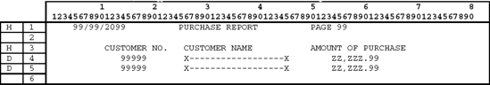
Using the following problem definition, print all fields on a single line for each input record. The printer spacing chart indicates how each output record is to be spaced. For readability, place a / between month, day, and year of the date. Also print headings at the top of each page of the report. Use WORKING-STORAGE with VALUE clauses for describing output lines.
Systems flowchart

Hierarchy chart

Record description layout for customer purchase file
Printer spacing chart for customer purchase report
Structured Pseudocode
Flowchart for Practice Program #1

Consider a program that reads records from the model file and prints a selection report.
Record description layout for model file

Notes:
Sex (M = male, F = female).
Color of eyes (1 = Blue, 2 = Brown, 3 = Other).
Color of hair (1 = Brown, 2 = Blonde, 3 = Other).
Draw a flowchart and pseudocode to print the names of all (1) blue-eyed, blonde males and (2) all females with brown eyes and brown hair (brunette).
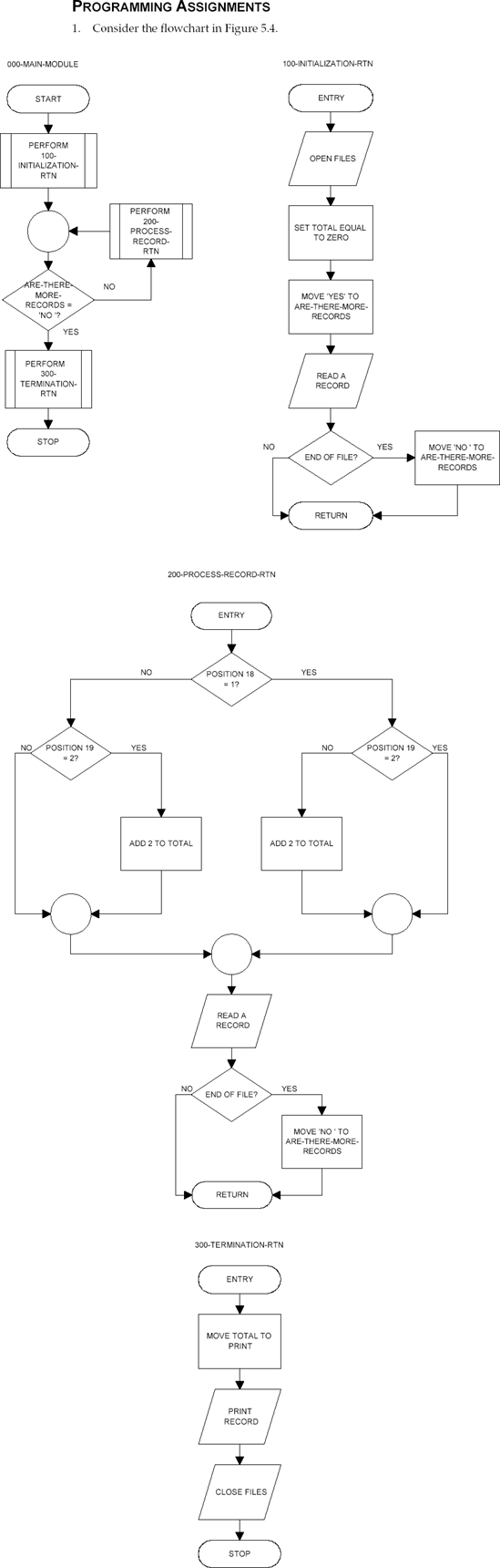
Consider the flowchart in Figure 5.4.
With the following input records, what is the content of TOTAL at the end of all operations?
Record Number
Contents of Record Position 18
Contents of Record Position 19
1
1
2
3
1
2
4
1
0
5
(blank)
(blank)
6
(blank)
1
8
1
2
9
1
2
10
(blank)
2
Write a pseudocode for the program logic depicted in Question 1.
Use the flowchart in Figure 5.5 to answer the following questions.
In this flowchart, a record is written on disk after reading how many input records? Explain.
The flowchart indicates that a record is printed after reading how many input records? Explain.
The flowchart indicates that a tape record is written after reading how many input records? Explain.
Write a pseudocode equivalent to the flowchart in Figure 5.5.