
Upon completion of this chapter, you should be able to
Describe design considerations when developing screen layouts.
Explain how a display file is used in an interactive program.
Demonstrate the ability to create and run an interactive program that uses a display file.
In previous chapters, sample problems used batch processing concepts. Batch processing means transactions are first gathered together, and then all transactions are processed as a group during one complete job. For example, businesses typically collect payroll data over a period of time and produce payroll checks for each pay period at one time. This is an example of batch processing, that is, collecting and holding all data until output is requested or needed, and then processing the batch all at once.
Several methods can be used for collecting data in a batch environment. In one such method, data are entered on a computer that is not even connected to the main computer system. This type of data entry for future batch processing is called an off-line operation. For example, payroll data might be entered at several corporate sites and then transmitted via telephone lines to the computer at corporate headquarters once a week so that paychecks can be produced in a batch processing operation.
Since batch processing does not process data immediately as it is transacted, users may not be getting the output from the computer at the time they need it. Thus, batch processing is useful only if there is no need to process records as soon as the data are transacted or entered. It may be that payroll files need to be current only at the end of a payroll period when it is time to produce checks; in such a case, batch processing is feasible, less costly, and more efficient.
In an on-line or interactive environment, processing occurs somewhat differently. Files are always kept current so that when data are transacted, the associated files are updated immediately. Any request for information can be answered by the computer immediately and will be up-to-date. Since on-line data are typically entered in a nonsequential manner, files that are to be updated immediately must be keyed files.
Stock exchange systems, for example, must be updated instantly so that stockbrokers know at all times exactly what offers and bids have been issued and what the current prices of stocks are. Stockbrokers require immediate information so that they can match bids to purchase with offers to sell. A stock exchange system, therefore, is an example of a system that uses on-line or interactive processing. On-line or interactive processing, then, refers to a system that provides immediate access to files, processes data immediately when they are entered, and always keeps files up-to-date.
Suppose, as another example, that someone wished to take a trip to Hawaii and called the travel agent to make the plans. The travel agent would access the airline reservations system to obtain the required information. Because the travel agent is on-line with the central computer, the agent will know immediately which flights are available, with which airlines, the departure and arrival times, and, most importantly, the cost of the flight.
In airline reservations systems, there are computer terminals at many sites, including travel agencies and airport airline desks. Although the terminals are off-site or at remote locations, they communicate directly and instantly with the central computer. These systems immediately update ticket information on all flights. Updating data in this manner is called an on-line operation, and the person at the terminal is said to be on-line with the main computer.
Display files are used in interactive applications as the interface between the user and the program. Display files are externally described objects (Type = DSPF) that define the record formats used by interactive programs.
A record format defines an entire screen or a portion of a screen that will overlap another screen. Each record format defines the fields and constants that are displayed on a particular screen. The fields may be defined as input fields, output fields, or both input and output fields. Constants, on the other hand, are the text displayed on the screen to provide identifying information and instructions.
As with all externally described files, data description specifications (DDS) are used to define display files. They are entered into a source member and compiled into an object (Type = DSPF) that can be used by an interactive program.
An interactive program uses a display file to produce output to a workstation. The record formats defined in a display file can contain company logos, department headings, data fields to be viewed or entered by the user, messages to the user, and so on. There are several types of record formats commonly used in interactive applications.
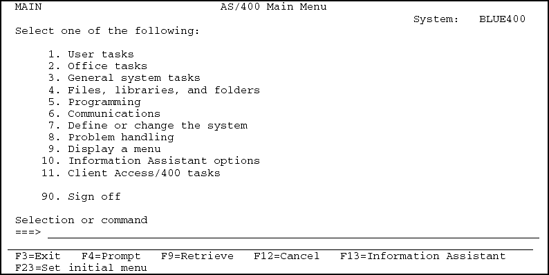
A menu format, such as the Main Menu in Figure 14.1, is designed to provide a list of functions or tasks from which the user can select.
An informational or query format, shown in Figure 14.2, is designed to provide information to the user. It does not allow new data to be entered into a file or existing data to be changed.

The informational format presents the user with a sequence of fields identified by captions or headings. Each field on an informational format is displayed in a way that the user cannot accidentally make changes to the existing data. That is, they are viewed but not changed by the user.
Consider a payroll application in which a user wants to inquire about a particular employee. The user enters the employee number as the key field. The program reads the employee number as input and randomly accesses the corresponding employee record from the keyed data file. Then, the program displays the information about the requested employee on the screen for the user.
In this type of interactive application, the user is only requesting information, and entering new data or updating existing data is not required.
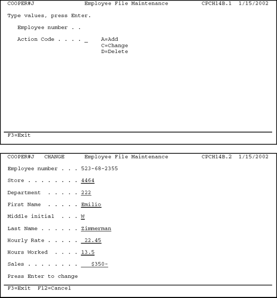
The data entry format, shown in Figure 14.3, presents the user with a sequence of captioned fields to be filled in with the required data. If the data being entered are new data, the captioned fields will be blank so the user will be able to add a new record to the file. If the user is changing an existing record in the file, the data entry screen will be displayed with the current data. Then the user can change only those fields that need to be updated. This type of record format is used to enter new data into a file or update existing records. When using a data entry format, the user must understand each caption or field heading and the permissible values allowed for each field.

A second, slightly different data entry format is shown in Figure 14.4, in which the screen is prompting the user to enter just one field, the employee number. When a single field is entered into a screen, as in this example, the application typically allows the user to enter a specific value and then the program uses that value to retrieve a particular record from a keyed file. Once the particular record is retrieved from the keyed file, the program displays a second record format containing the requested information. Thus, in this example, the program uses the employee number entered by the user to retrieve and display the specific employee information.

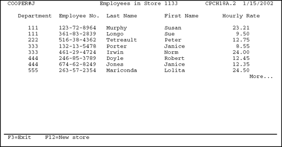
A list or work with format, shown in Figure 14.5, provides a method of displaying a subset of records on the screen. This type of processing is called subfile processing and will be covered in detail in a later chapter. Subfile processing allows the user to narrowly define a subset of records within a file to view a group of records. For example, in Figure 14.5 the employees that work at store number 1133 are displayed.
Subfiles are also used to help find the actual record that is being searched for. For example, consider what happens when someone goes into the bank to conduct a transaction and forgets his or her account number. The teller can enter the person's last name into a program that creates a list of customers with the same last name on the screen. This list contains a subset of the records from the account file that the teller can use to narrow down the search for the person's account number. From here, the teller will be able to the find the account number by using the person's address or other identification.
If a program includes interactive dialogue between the user and the program, the software developer must carefully design the elements of that exchange. The exchange must be clear, concise, and as user-friendly as possible.
Examine the different record formats in Figures 14.1 through 14.5 and notice that all the record formats have the same general layout. Let us consider these record formats to discuss some of the general layout concepts that should be considered when designing record formats. Not every concept need be incorporated into every record format. The final design of a record format depends upon the application and the users who will be interacting with the application.
Screen Layout. The screen layout should be informative but not cluttered. Vertically align data for ease of reading. Most screens display 24 lines with 80 characters per line. Include blank lines and wide margins to achieve an uncluttered look.
Identification Title. Every record format that displays data to a user should have a title. This title could be the company name or the application name, such as Employee Pay File Inquiry, Payroll Hours Update, Accounts Payable, and so on.
Prompts. Directions to the user, called prompts, should be clear and concise. Enter employee number is a relatively clear and concise prompt. If the word Enter is used in an exchange, the same word should be used in other prompts within the same program. That is, it could be confusing to change to a different type of prompt such as Key in employee number or Type in employee number. If terminology is standardized, there will be fewer misunderstandings. Depending on the experience of the user, the software developer may want to add prompts such as Then press Enter or Press Enter to display employee information. Such prompts may be obvious to an experienced user, but they may not be obvious to a novice.
Options. Where appropriate, provide the available options at the top of the screen. From the option list, the user selects an option by entering the appropriate number. The program evaluates the option entered by the user and proceeds to the appropriate routine.
Optional Record Format Identification. Although software developers try to plan for all situations, they sometimes do not succeed. Consequently, now and then a user inadvertently causes an interactive application to terminate abnormally. Imagine a user in a remote office running a critical month-end procedure. A problem occurs, and the user calls the information technology (IT) department for help. For the person in the IT department to be able to help the user, the best information the user can supply is the program identification, consisting of the program name and record format number shown at the top of the screen. With this information, no one has to search to identify the program, and assistance can be provided immediately to the user.
Optional Action Code. The action code identifies the action required by the user. In the example in Figure 14.3, the action code is CHANGE, which means that the user may change data shown on the screen. If a user had requested a program that allowed only queries into the file to view information, that action code could be specified as VIEW or QUERY. Thus, the action code provides immediate direction (ENTER, CHANGE, or VIEW) for the user.
Optional Date. Some users may find displaying the date at the top of the screen helpful when running an application.
Optional User Identification. The user identification can be displayed at the top of the screen to identify who is signed on to the workstation. This can be helpful when users share a workstation.
Field Captions. Field captions, such as Employee Number, Store, and so on, are to display file record as column headings are to printed reports. That is, they provide identification for the different fields that appear on the record format.
Fields Defined for Input. When a record format is displayed that requires the user to enter new data into the field, these fields are defined as input or data entry fields. Input fields may be used to create new records or update existing records in a file.
Fields Defined for Output. Unlike input fields, output fields are displayed to the user. The user is not permitted to enter data into fields specified as output-only fields. This protects the user from accidentally making changes to data.
Fields Defined for Both Input and Output. Sometimes a user may want to view fields to determine if modifications are required. When this is necessary, fields are defined as both input and output, or I/O, fields.
The program first displays the fields as output fields to allow the user to view the necessary information. If required, the user then enters new data into the fields, which are then read into the program as input and used to create a new record in the file or change existing data in the file.
Function Key Area. In most interactive applications, function keys are specified at the bottom of the screen and are used extensively to aid in the selection of the different actions available to the user. Normally when a user is running an interactive program several courses of action will exist for a record format. For example, the user may press F12 to cancel the current operation, F5 might be used to refresh the screen back to its original values, or F3 might be used to exit and end the job. These function key options are placed at the bottom of the screen.
Message Area. A special area is normally established on the screen so that error messages can be communicated to the user. Once the user reads the error message, he or she can take the appropriate action to correct the error. Error messages are normally highlighted in some fashion and placed on line 24 to draw the user's attention.
Attributes. Attributes are special characteristics that determine how a field or constant will appear on the screen when a record format is displayed to the user. These attributes help draw the user's attention to a specific field or constant on the screen. Attributes are discussed in more detail in the next section.
As mentioned, special characteristics called attributes are used to define how fields and constants are displayed on the screen to the user. Reserved keywords are used to define the attributes of a constant or field. Two commonly used attribute keywords are COLOR and DSPATR (Display Attribute).
Color. The COLOR keyword is used to display certain data in color. The user-friendliness of a system can be greatly improved by incorporating color into the display screen. For example, using the color red for error messages or fields in error may enhance the readability of the screen. Another example might be to distinguish user entries from computer responses by the use of different colors. Or, if headings are required, you may want to display a company's name in color.
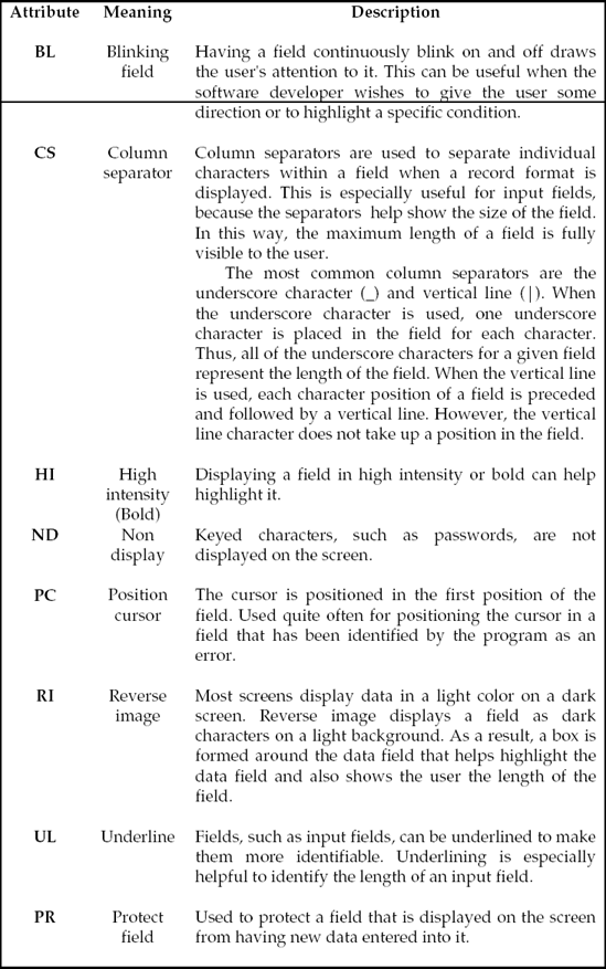
DSPATR Keyword. The DSPATR keyword is used to define certain attributes of a field or constant defined in the record format. The DSPATR keyword can be specified more than once for a field. In addition, more than one attribute may be specified with the same DSPATR keyword. The format for the DSPATR keyword is DSPATR (attribute1 attribute2, etc).
The DSPATR keyword may be assigned to constants, input fields, output fields, and fields defined as both input and output. Figure 14.6 identifies some of the more common attributes that can be assigned.
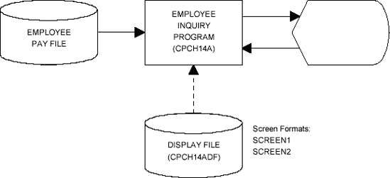
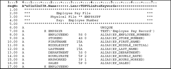
Program CPCH14A is an interactive query program that randomly retrieves employee records from the employee pay file and displays the employee pay information on the screen. Such information as the employee name, hourly rate, hours worked, and sales are displayed on the screen. Figure 14.7 illustrates the systems flowchart for this case problem. Figure 14.8 contains the data description specifications (DDS) for the employee pay file, which uses a 9-byte employee number field (positions 1–9) as its key field.
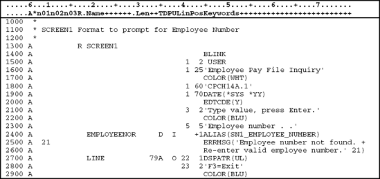
This case problem demonstrates the concepts of interactive programming using a display file. The first record format, SCREEN1 in Figure 14.9, is an entry format that prompts the user for an employee number so the corresponding record can be retrieved from the data file. The SCREEN1 record format contains the constant Employee Pay File Inquiry that is used to identify the display. It also contains a prompt, labeled Employee Number., and an input area where the user enters the employee number. When the input area for the employee number appears on the screen, underscores also appear where the user is to enter the employee number. These underscores represent the length of the field. There will be a blinking cursor, which is a blinking square or underscore, to remind the user that an entry is required.

Using the employee number entered by the user, the program randomly retrieves the requested record from the employee pay file. If the employee number is found in the employee pay file, record format SCREEN2 in Figure 14.10 is displayed on the screen. Record format SCREEN2 is an informational screen used to display the employee number, employee name, hourly rate, hours worked, and sales for the requested employee.
Once the user is finished viewing the information on SCREEN2, he or she presses Enter, F3 (Exit), or F12 (Cancel). When Enter is pressed, format SCREEN1 is again displayed so that the user can select another employee to view. In this example, pressing Enter or F12 will accomplish the same thing, that is, display SCREEN1 again. If the user presses F3, the program terminates.

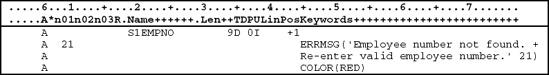
If the employee number requested by the user is not found in the file, the program will use a 1-byte indicator, or switch, to communicate the error to the display file. Indicators, or switches, used in this manner are 1-byte fields that contain the value 1 (ON) or 0 (OFF). When the indicator is on and SCREEN1 is written back to the screen, the error message Employee number not found. Re-enter valid employee number is displayed, as in Figure 14.11.

Program CPCH14A allows the user to continue to view records from the employee pay file until the user signals the end of job by pressing F3 (Exit), at which time the program is terminated.
The first step in writing an interactive program is to design the record formats for the display file that will be used for communication between the user and the program. Data description specifications are used to lay out the record formats as they will appear on the display screen.
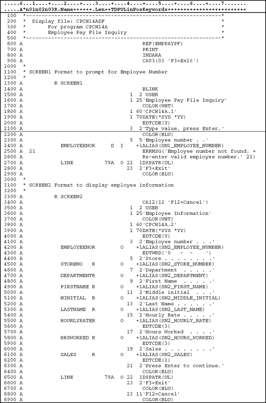
The complete DDS for the CPCH14ADF display file are shown in Figure 14.12. The display file contains two record formats: SCREEN1 and SCREEN2.
All DDS specifications have the letter A in position 6.
Lines 1.00–5.00: An asterisk in position 7 indicates a comment line. Comments are used to describe the DDS source. They do not become part of the object when the source DDS are compiled.
The left side of the DDS (positions 7–44) has specific positions for specific functions. Positions 45–80 are the Functions or Keyword area. This area is more free-form and allows a wide variety of entries. Keywords include BLINK, ERRMSG (error message), EDTCDE (edit code), EDTWRD (edit word), USER, and COLOR.
As with all externally described files, the DDS for display files contain entries at the file, record, and field levels. The file level appears at the beginning of the DDS and defines characteristics that apply to the entire display file. The record level follows the file level and is used to describe characteristics that apply to each record format of the display file. Following the record level is the field level, where each field and constant is defined.
File-level specifications are defined at the beginning of the display file. The DDS entries for the file level specification are shown in Figure 14.13. A description of each line follows the figure.

File Level (Lines 6.00–9.00)
Line 6.00: The file-level keyword REF indicates that there are fields in this display file that are defined in another file but referenced in this display file. The REF keyword is used to identify the file that will be referenced to obtain the field attributes. In this example, the display file references the physical file EMPPAYPF.
Line 7.00: The PRINT keyword enables the print screen function. Since the PRINT keyword is defined as a file-level keyword, the user will have the ability to perform a print screen operation on all record formats defined in the display file.
When writing interactive programs, indicators, or switches, are used to communicate between the interactive program and the display file. These indicators are Boolean data items. Boolean data is a category of data that is limited to a value of 1 or 0. They can be used to (1) condition the attributes of a display file during the processing of an interactive program and (2) reflect function key responses that can control the processing of a program by relating function keys to indicators (switches) within the program.
Each function key is assigned to an indicator defined in the interactive program. When a function key is pressed, the associated indicator in the program is set to true (value of 1). The indicator is then used to condition operations in the program. Only those function keys specified in the display file are enabled for that display file. In addition, when the function key can be used depends on where the function key is defined in the display file. For example, if the function key is defined at the file level, then the function key is enabled for all record formats. If, however, the function key is defined at the record level, then the function key is enabled for that record format only. If the user wishes to select a function key and presses a disabled function key by mistake, a system error message appears.
Indicators are often used in DDS to condition options, such as underlining and message handling. In addition, indicators are used to identify particular responses from the interactive program, such as whether a function key was pressed. As already stated, indicators are Boolean data items that can have the values 0 or 1. These indicators are passed from the display file to the program by (1) including them in the record formats or (2) defining them outside the record formats in a separate indicator area. The sample programs in this book use the separate indicator area to pass indicators from the display file to the program.
Line 8.00: The file-level keyword INDARA indicates that all indicators defined in the display file are passed to and from the program in a separate indicator area (INDARA). They are not defined as part of the record formats. Later in the chapter we explain how this separate indicator area is defined in the interactive program.
Line 9.00: The CA03 (03 'F3=Exit') line establishes a connection between the function key F3 and the indicator 03 defined in the program. The CA03 portion establishes F3 as a valid function key for this display file. Since this line is defined at the file level, F3 is enabled for all record formats in the display file. CA stands for Command Attention, which tells the system to return control to the program without returning any data that the user might have entered. So, regardless of whether the user has entered any data, pressing F3 informs the program only that the F3 key was pressed.
Another way of defining Function keys is to use CF (Command Function). If the line had been coded as CF03 (03 'F3=Exit'), control would return to the program with any data the user may have entered.
The 03 inside the parentheses associates the F3 function key with indicator 03 in the program. So when F3 is pressed, indicator 03 is set on in the program. Interactive programs cannot reference any of the function keys directly in the program. So an indicator is assigned to each function key used in the display file.
Any information within apostrophes, 'F3=Exit' in this case, serves as documentation only and could be omitted. Thus, this line could have been coded as CA03 (03).
As noted, data description specifications are used to describe the record formats for a display file. The DDS entries for the SCREEN1 record format are shown in Figure 14.14. A description of each line follows the figure.
Lines 10.00–12.00: Comment lines pertaining to the record level DDS for SCREEN1.M
Record Level (Lines 13.00–14.00)
Once the characteristics for the entire display file have been defined at the file level, each record format must be defined.
Line 13.00: The record format is identified at the record level by the letter R in the Name Type field (position 17). A unique name is assigned to the record format, SCREEN1 in this example, and is left-justified in the Name field (positions 19–28). Record format names can be up to 10 characters in length and must begin with an alphabetic character or one of the special characters: @, $, and #. The remaining characters in the record name may be A-Z, 0–9, @, $, #, and the underscore (_) character. Embedded blanks are not allowed.
Line 14.00: This line contains the keyword BLINK. BLINK is a keyword associated with the cursor and tells the system that the cursor is to blink when this record format is displayed on the screen.
Field Level (Lines 15.00–29.00)
Each field level specification completely describes an element of the record format. Constants and data-fields are defined here in the sequence in which they will appear on the screen.
Line 15.00: The keyword USER retrieves from the operating system the name of the current user who is signed on to the workstation. The USER profile name is displayed on line 1 beginning in position 2.
The user-friendliness of a system can be greatly improved by incorporating color into the record formats of a display file. The COLOR keyword is used to display portions of the record format in color. For example, in Figure 14.15 the constant 'Employee Pay File Inquiry' is displayed on the screen in white (WHT).

Figure 14.16 provides another example in which an error message is displayed in red. Using a specific color for error messages or fields in error may enhance the readability of the screen.
Another example would be distinguishing user entries from computer responses by the use of different colors. Or, if headings are required, a company's name could be displayed in color. Other color options are
Attribute | Color Displayed |
|---|---|
BLU | Blue |
GRN | Green |
WHT | White |
YLW | Yellow |
PNK | Pink |
TRQ | Turquoise |
RED | Red |
Line 16.00: The first line of the field level is a literal, because Employee Pay File Inquiry is enclosed within apostrophes and defined in position 45. The 1 right-justified in the Line field (positions 39–41) indicates that this literal will appear on line 1 of the screen when SCREEN1 is displayed. The 25 right-justified in the Pos field (positions 42–44) indicates that the literal will appear on the screen beginning in position 25.
Line 17.00: The keyword COLOR is used to specify in which color to display the associated field or constant. In this case, Employee Pay File Inquiry is displayed in white.
Line 18.00: The program name and record format number appear on line 1 beginning in position 60. CPCH14A. 1 is enclosed within apostrophes and defined in position 45. The 1 right-justified in the Line field (positions 39–41) indicates that this literal will appear on line 1 of the screen when SCREEN1 is displayed. The 60 right-justified in the Pos field (positions 42–44) indicates that the literal will appear on the screen beginning in position 60.
DATE is a reserved word that internally stores the system date as an 8-digit field. When specified, the system date will be retrieved and displayed in the location specified in the Positions field (positions 42–44). The format for the DATE keyword is DATE(*SYS *YY) The *SYS parameter specifies that the current system date is displayed. The *YY specifies that four digits are used to represent the year
Lines 19.00–20.00: DATE is left-justified in the Name field (positions 19–28). This field is eight digits long. The O in the Usage field (position 38) indicates that this field is an output field. This field is used to display the current system date when the program is executing.
The EDTCDE(Y) keyword tells the system to edit DATE so that it displays with slashes as month/day/year.
Line 21.00: Type value, press Enter is a literal that will appear on line 3 beginning in position 2.
Line 22.00: The constant Type value, press Enter is displayed in blue.
Line 23.00: On line 5 beginning in position 5, the literal Employee number. appears. This literal serves as a field caption for the Employee Number field in which data will be entered from this screen.
Line 24.00: The Employee Number field, EMPLOYEENO, is left-justified in the Name field (positions 19–28).
Notice that there is no entry in the Length field. Also notice the letter R in the Reference field (position 29). The R in the Reference field is associated with the REF keyword at the file-level area (line 6.00). It tells the system to refer to another file, EMPPAYPF in this case, for the attributes of this field. When a reference is made to another file, the field's data type, length, decimal positions, and keyword attributes are retrieved from the referenced file. So these attributes do not have to be defined in the display file.
The letter D in the Data Type field (position 35) indicates that only the digits 0 through 9 are allowed as input into this field. Before we continue with the DDS, let us consider some of the different data types for display files.
Data Types (Position 35) Used in Display Files
A field's data type is specified in the Data Type field (position 35). The Data Type field is sometimes referred to as data type/keyboard shift, because there are more data types that can be entered from the keyboard of a workstation file than with fields defined in physical files. The data types listed in the chart in Figure 14.17 are the most common.

The Data Type field (position 35) is optional. If omitted, a field will be defined according to the default data types listed in Figure 14.18.

ALIAS Keyword: Like physical files, display files allow a data field to have an alternative (ALIAS) name of up to 30 characters. When the ALIAS keyword is used, the ALIAS name, SN1_EMPLOYEE_NUMBER in this instance, may be used in the program instead of the field name EMPLOYEENO in the Name field (positions 19–28).
Lines 25.00–26.00: The ERRMSG keyword is associated with a field so that additional information can be provided to the user when an error condition occurs. When an error condition is in effect for a field, two things happen. First, the message assigned in the ERRMSG keyword is displayed on the message line at the bottom on the screen. Second, the field associated with the ERRMSG keyword is redisplayed in reverse image to provide the user with a method of associating the field and the error message.
The format for the ERRMSG keyword is
ERRMSG ('error message text' [indicator]).
As well, one or more indicators are assigned to the ERRMSG keyword in the Conditioning field (positions 7–16). When the program detects an error condition regarding the associated field, the conditioning indicator is set on in the program. When the record format is redisplayed, the conditioning indicators in positions 7 through 16 determine if the ERRMSG keyword should be activated or not.
The keyword ERRMSG is followed by two parameters in parentheses. The first parameter, enclosed in apostrophes, is the error message that will appear on the message line if an error occurs. The second parameter is an optional indicator that is set off when the record format is read back into the program after the error condition is displayed. Thus, the conditioning indicator used to activate the ERRMSG keyword can be turned off when the record format is returned to the program.
In CPCH14ADF, indicator 21 is used to activate the ERRMSG keyword. The error condition will only take place if indicator 21 is set on in the program. Indicator 21 is also turned off when the record format is returned to the program.
Line 27.00: A 79-byte alphabetic field called LINE is defined. This field is displayed on line 22 beginning in position 1. The keyword DSPATR(UL) tells the system to underline this field when it is displayed on the screen. Nothing will be placed into this field during processing, and thus this field will appear as a line across the screen to separate the function keys at the bottom of the screen.
Line 28.00–29.00: On line 23 beginning in position 2, the literal F3=Exit appears. This literal serves as information to the user. This line has nothing to do with the actual assignment of the F3 key. The constant F3=Exit is displayed in blue.
The second record format, SCREEN2, is defined after SCREEN1 has been defined. Figure 14.19 illustrates the DDS for the record format for SCREEN2. A description of the DDS follows the figure.

Lines 30.00–32.00: These lines are comment lines used to identify the record format.
Record Level (Lines 33.00–34.00)
Line 33.00: The record format for SCREEN2 is defined. Like all other record formats, it is identified by the letter R in the Name Type field (position 17). The name of the record format, SCREEN2, is left-justified in the Name field (positions 19–28).
Line 34.00: The CA12 (12 'F12=Cancel') line establishes a connection between F12 and indicator 12 in the program. The CA12 portion establishes F12 as a valid function key for this record format. Since this line is defined at the record level, F12 is enabled for record format SCREEN2 only. F12 is defined as a Command Attention (CA) key, which tells the system to return control to the program without returning any data fields that the user might have entered.
Field Level (Lines 35.00–69.00)
Line 35.00: The USER profile name is displayed on line 1 beginning in position 2.
Line 36.00–37.00: Employee Information will appear on line 1 (1 in Line field) beginning in position 25 (25 in Position field). The constant Employee Information is displayed in white.
Line 38.00: This record format is identified by the literal CPCH14A.2. This literal appears on line 1 beginning in position 70. CPCH14A.2 is enclosed within apostrophes and defined in position 45. The 1 right-justified in the Line field (positions 39–41) indicates that this literal will appear on line 1 of the screen when SCREEN1 is displayed. The 70 right-justified in the Position field (positions 42–44) indicates that the literal will appear on the screen beginning in position 70.
Line 39.00–40.00: The keyword DATE defines the system date field. The EDTCDE(Y) keyword tells the system to separate each component of the date field with a slash (/).
Line 41.00: This line defines the literal for the employee number that will be displayed on the screen. Employee Number . . . appears on line 3 (3 in the Line field) beginning in position 2 (2 in the Position field).
Line 42.00–43.00: The Employee Number field, EMPLOYEENO, is left-justified in the Name field (positions 19–28). The R in the Reference field tells the system to retrieve the attributes for this field in the EMPPAYPF file.
The O in the Usage field (position 38) indicates that this field is an output field. That is, this field can only be displayed on the screen. The user will not be able to enter data (input) into the field.
When the employee number is displayed on the screen it will appear one (+1) position to the right of the constant Employee Number . . . . The line and position numbers are not specified. Instead, the +1 tells the system to associate this field with the previous line and to position it one position to the right.
The alternative name SN2_EMPLOYEE_NUMBER is assigned to this field with the ALIAS keyword in position 45. In this way, SN2_EMPLOYEE-NUMBER can be used in the program instead of EMPLOYEENO.
Note the use of the EDTWRD keyword. The EDTWRD keyword provides a method of editing a numeric field. In this example, the employee number will appear with hyphens (-) separating the digits. We discuss editing of numeric fields and the EDTWRD keyword in the next section.
Lines 44.00–62.00: These lines define the output fields that will be displayed along with the literals used to identify them. All eight fields refer to the EMPPAYPF for their attributes and use an alternative name for COBOL processing. Note the use of the EDTCDE keyword. We discuss editing of numeric fields and the EDTCDE keyword in the next section.
Lines 63.00–64.00: These lines define a literal that tells the user the Enter key is to be pressed to continue with the query. The literal will appear in blue.
Line 65.00: A 79-byte alphabetic field called LINE is defined that is displayed on line 22 beginning in position 1. This provides a line on the screen to separate the function keys at the bottom of the screen.
Lines 66.00–69.00: Line 66.00 indicates that F3 is pressed to Exit and terminate the program, while line 68.00 indicates that F12 allows the user to cancel the current operation. Both literals are displayed in blue.
These lines are displayed as literals on the screen. They do not influence the program in any way. For example, F3=Exit is displayed on line 23 beginning in position 2. This line does not have any connection with the defining of the F3 indicator at the file level of SCREEN1.
When a numeric field is specified as an output field, edit codes and edit words may be used to make the data easier to read. If editing is performed on output fields, the length of the field must be adjusted accordingly to allow for the additional edit characters.
Most of the editing functions can be accomplished with the use of the EDTCDE (edit code) keyword. The chart in Figure 14.20 provides the most common edit codes that are used.
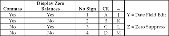
Figure 14.21 provides a better understanding of the results when edit codes 1 through 4 are specified for an output field.

Suppose, for example, that an amount field is to be displayed so that
Commas are included.
Zero balances are displayed.
No sign is to be displayed, even if the amount is negative.
Examine the charts in Figures 14.20 and 14.21 and observe that edit code 1 is used to provide the necessary editing features required in this situation. Thus, the EDTCDE keyword would be specified as EDTCDE(1). Similarly, suppose an edited numeric field is to be displayed without commas, with a zero to denote a zero balance, and with no sign; the edit code EDTCDE(3) would be specified.
In addition to the above edit characteristics, the use of the EDTCDE keyword automatically
Suppresses leading zeros (so that 007 displays as 7). Zero suppression means that nonsignificant zeros are replaced with blanks.
Places a decimal point in the appropriate position when the field is displayed as indicated in the decimal positions field.
Edit codes A-D and J-M are used if a field can contain a negative amount. A sign will not be displayed unless an appropriate EDTCDE keyword is used. To display a minus sign for negative quantities, use edit codes J-M in the EDTCDE keyword. The sign will be displayed to the right of the number. EDTCDE(J) will cause the same editing as EDTCDE(1), but it will also display a minus sign for negative values. For example, to display a sales field containing −01150 as ▵1,150-, the EDTCDE keyword is specified as EDTCDE(J).
Similarly, K, L, and M will result in the same editing as edit codes 2, 3, and 4, respectively, but minus signs will also be displayed for negative amounts.
An edit code of A-D is used just like 1–4 and J-M except that CR is displayed for negative amounts instead of a minus sign. CR stands for credit.
If a numeric field is to be displayed with zero suppression, but no edit code is being used, the zero suppress edit code (Z) may be used. For example, to display a sales field containing 00500 as ▵▵500, the EDTCDE keyword is specified as EDTCDE(Z).
To float a dollar sign on a displayed field, include the $ constant in the EDTCDE keyword. For example, if EDTCDE(1 $) were specified for a five-digit Sales field containing 01250, the displayed results would be $1,250. If positive and negative values were allowed in the Sales field, the EDTCDE of 1 could not be used because it does not allow a sign to display with the field or be entered into the field. Instead, EDTCDE(J $) could be used so a sales value of -$50 could be entered into the field and displayed as a negative value on the screen.
Certain editing operations cannot be performed with edit codes. Instead, the EDTWRD keyword is used to provide the necessary symbols desired. To define an edit word, an edit pattern must be established to indicate the format of the displayed output. The field to be edited is called the sending field. It interacts with the edit pattern by replacing the spaces in the pattern with the digits from the sending field.
The edit word, or pattern, is enclosed in apostrophes or single quotes. The example in Figure 14.22 illustrates how an edit word displays dashes or hyphens in a Social Security number (Employee Number). Note that the sending field consists of nine digits, while the edit word occupies 11 positions in the EDTWRD keyword.
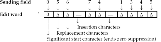
In an edit word, some of the characters occupy a position in the output field and display exactly as shown in the edit pattern. They are called insertion characters. In our example, we use the hyphen as an insertion character, but the dollar sign, decimal point, comma, and others can be used.
The blanks or spaces, ▵ in this example, are called replacement characters. These blank characters are replaced by the digits in the field to be edited (the sending field). Therefore, insertion characters display exactly as shown, while the digits replace the spaces stored in the sending field.
The number of replacement characters in the edit word must be equal to or greater than the number of digits contained in the field to be edited. If an edit word is specified that is to small to hold the results, high-order truncation, or loss of the high-order digit(s), will occur.
Typically, when fields are displayed that contain dollars and cents, we would want the leading zeros to be suppressed, that is, to be replaced with blanks. But in the case of a Social Security number, we want all nine digits to be displayed even if the first digit is zero. We therefore want to prevent zero suppression in this instance. The significant start character, 0, in the leftmost position of the edit pattern enables the program to display all nine digits, even if they are all zeros. If zero suppression is required, the significant start character zero is changed to a blank and a zero is placed where zero suppression is to end. For example, ▵▵,▵0▵ terminates zero suppression at the tens position so that 00005 would be displayed as 05. The high-order zero in the edit pattern of our illustration indicates that all characters to the right will be displayed even if they are zeros. If the zero had been omitted and the first digit of the Social Security number was a zero, then the zero would be replaced with a blank and the displayed results would be incorrect. Since the zero is used to terminate zero suppression, we call it a significant start character.
Before a display file can be utilized in a program, it must be compiled into an object. This is done after the DDS for the display file have been entered as a source member. The CRTDSPF command is used to compile source DSS into an object. To compile our display file called CPCH14ADF, the following command could be entered:
CRTDSPF CPCH14ADF
Another method that can be used to compile the source member into an object is to enter 14 in the Option field beside the source member name on the Work with Members Using PDM screen. Option 14 will submit to batch the CRTDSPF command that will compile the display file into an object.
Note that the task of designating and generating the display file is not part of the actual program that will use it but rather is handled separately.
Programs written for interactive applications refer to this type of processing as WORKSTATION file processing because the computer used to communicate to the user is defined in the program as a WORKSTATION device. The WORKSTATION device is defined as a special type of file called a TRANSACTION file. This allows the program to read records from or write records to the workstation device.
A SELECT statement is used to establish a TRANSACTION file name and assign the file to a WORKSTATION device. An example of a SELECT statement for a TRANSACTION file is shown in Figure 14.23.

The SELECT clause is used to establish or assign a display file for processing. To use a display file in a COBOL/400 program, the file must also be identified by a FD entry in the DATA DIVISION as shown in Figure 14.24.
In interactive programs, display files are usually externally described. When the COBOL/400 program is compiled, the Format 2 COPY creates the DATA DIVISION statements to describe the display file. The DDS-ALL-FORMATS option of the Format 2 COPY statement generates one storage area for all the record formats.
The ORGANIZATION IS TRANSACTION clause in the SELECT statement allows an interactive program to send or receive records to and from a workstation device. When ORGANIZATION IS TRANSACTION is used in an interactive program, records are read from and written to the display file using the READ and WRITE statements.

WORKSTATION file input and output records must be described in the program according to the record formats generated by the compile of the display file source member. The record length for a display file is obtained from the display file object. Constants, such as the headings and field captions, are maintained with the record formats in the display file object. The program, then, does not have to describe them.
The record formats will be copied into the program, and record layouts are established in the program for use. Fields that will be input to or output from the interactive program are the only items defined in the program.
The device type WORKSTATION must be specified in the ASSIGN clause. The ASSIGN clause associates the TRANSACTION file with the display file, CPCH14ADF in our example.
The SELECT statement for a display file that has INDARA specified in its DDS must have the separate indicator area attribute, SI, as part of the assignment-name. In Figure 14.25, the SELECT statement for the WORKSTATION file is CPCH14ADF-SI. The SI indicates that indicators are stored in a separate indicator area.
Since a separate area is used to store the indicators, the Format 2 COPY statement for DISPLAY-FILE generates data descriptions in the record area for data fields only. The data description entries for the indicators are not generated, because a separate indicator area, WS-INDICATOR-LIST, has been defined.
The group item, WS-INDICATOR-LIST, defines data description entries in the WORKING-STORAGE-SECTION for all indicators used in the DDS for the display file. Meaningful descriptions are assigned to each condition with Level-88 condition-names.
The INDICATORS phrase shown in the WRITE statement in Figure 14.21 is used in READ and WRITE statements when it is necessary to send the indicator values to and from the display file. For example, if the user enters an incorrect value in the Employee Number field, the program sets indicator 21 (IN21 - EMPLOYEE-NUMBER-NOT-FOUND) to TRUE (B'1'). When it is necessary to display the error message, the SET EMPLOYEE-NUMBER-NOT-FOUND TO TRUE statement is used to move the Boolean value B'1' to IN21 (indicator 21). In Figure 14.12, indicator 21 is specified on line 25.00 to tell the system to display the error message that is specified in position 45.

Function keys are also defined in the DDS as indicators. COBOL/400 programs, however, will not recognize function keys. So, indicators are assigned to the function keys and passed between the display file and the program. Normally, the same numbered indicator is assigned to the function key. For example, indicator 03 is assigned to function key F3, indicator 12 is assigned to function key F12, and so on.
Function keys may be defined in the separate indicator area along with the other indicators used in the program. Another method of defining function keys is to use the CONTROL-AREA clause in the SELECT statement as shown in Figure 14.26.

The CONTROL-AREA clause refers to a group item that is used to obtain specific information for controlling input-output operations for TRANSACTION files. The control area can be 2, 12, or 22 bytes long. Thus, only the first 05-level element, the first two 05-level elements, or all three 05-level elements are specified, depending of the type of information required in the program. The control area data item identifies
The function key pressed by the user to initiate a transaction.
The name of the program device used.
The name of the DDS record format that was referenced by the last I-O statement.
The first variable, WS-FUNCTION-KEY, contains the Function key pressed by the user to finish the processing of a screen. If the user presses the Enter key and not a Function key, the WS-FUNCTION-KEY field contains zeroes. With this technique, level-88 condition-name entries are assigned to the conditional variable WS-FUNCTION-KEY. WS-FUNCTION-KEY-03, WS-FUNCTION-KEY-12, and NO-FUNCTION-KEY-WAS-PRESSED are condition-names. When a reference is made to a condition-name, the conditional variable, WS-FUNCTION-KEY in this example, is tested to determine whether its value is equal to the value associated with the condition-name (level-88 item). The result of the test is true if the value corresponding to the condition-name equals the current value of the associated conditional variable. Only one of the values specified in the condition-name entries can be present or true at one time.
When a user presses a Function key, F3 for example, the Function key value (F3 = 03) is placed in the conditional variable WS-FUNCTION-KEY. Since the value assigned to the condition-name WS-FUNCTION-KEY-03 is equal to the conditional variable WS-FUNCTION-KEY, WS-FUNCTION-KEY-03 can be used to control processing in the program.
When a condition such as IF NO-FUNCTION-KEY-WAS-PRESSED is tested, an implicit comparison of the condition-name (NO-FUNCTION-KEY-WAS-PRESSED) with the condition variable (WS-FUNCTION-KEY) takes place, even though the condition variable WS-FUNCTION-KEY is not referenced in the IF statement. If the value of the condition-name NO-FUNCTION-KEY-WAS-PRESSED equals the value in WS-FUNCTION-KEY, the result is true and the IF statement is executed.
READ and WRITE statements are used to process screen I/O for a display file.
The WRITE statement displays or writes a record format to the screen and returns control to the program without waiting for user input. The following is an example of the WRITE operation.
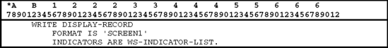
The value specified in the FORMAT phrase contains the name of the record format to use for the I-O operation. The system uses this to specify or select which record format to operate on.
When the WRITE operation is executed, record format SCREEN1 is written to the screen.
The READ operation sends control to the operating system, which waits for the user to respond to the currently displayed screen. The following is an example of the READ operation.
The user responds by pressing Enter, by pressing an active function key, or by pressing another enabled special key such as Page Up or Page Down. Once the user responds, the program reads the record format from the screen. If the data are available, they are returned in the record area. The names of the record format and the program device are returned in the I-O-FEEDBACK area in the CONTROL-AREA.
The FORMAT phrase is optional, and if it is not specified the current record displayed on the workstation is returned to the program.
Figure 14.27 illustrates the entire program required for this interactive inquiry application.
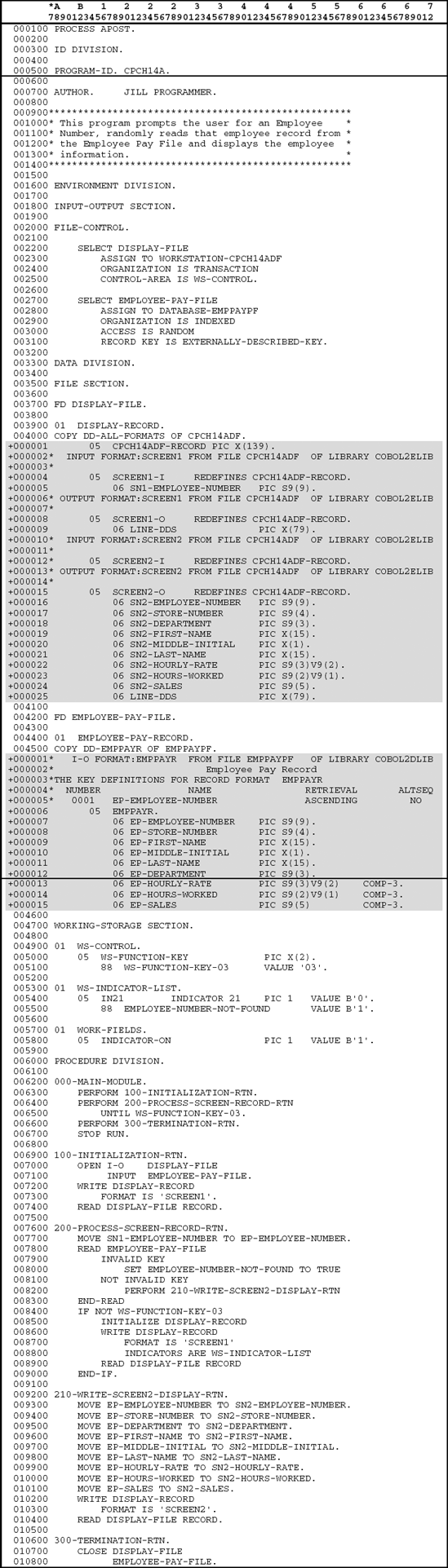
The initialization subroutine, 100-INITIALIZATION-RTN, is executed first from the 000-MAIN-MODULE. Notice that the DISPLAY-FILE is opened as I/O to allow the program to READ and WRITE records to the workstation file. After the files are opened, a WRITE statement sends the record format for SCREEN1 to the WORKSTATION file. SCREEN1 prompts the user to enter an employee number.
The user has two choices when SCREEN1 is displayed: (1) enter an Employee number and press the Enter key or (2) press F3 (Exit) to terminate the program.
Once the user has responded to SCREEN1, the READ operation reads SCREEN1 from the WORKSTATION file into the program. If the user had decided to terminate the program by pressing F3 (Exit), WS-FUNCTION-KEY would contain 03, indicating that the user pressed F3, and the program would be terminated.
200-PROCESS-SCREEN-RECORD-RTN If the program is not terminated, control is passed to the PERFORM statement, which continues to execute 200-PROCESS-SCREEN-RECORD-RTN until the user presses F3 on either SCREEN1 or SCREEN2. Once F3 is pressed, the PERFORM statement stops executing and the 300-TERMINATION-RTN is executed.
Once inside 200-PROCESS-SCREEN-RECORD-RTN, the field SN1-EMPLOYEE-NUMBER is moved to EP-EMPLOYEE-NUMBER in preparation for the read to the keyed file. Next, a READ operation is performed to retrieve the requested record from the employee pay keyed file.
When the READ statement is executed, there are two possible results. The first possibility is that the user entered an invalid employee number and EMPLOYEE-NUMBER-NOT-FOUND is set to TRUE. EMPLOYEE-NUMBER-NOT-FOUND is a condition-name that is associated with indicator 21 and is defined in WS-INDICATOR-LIST. This forces the error message to be displayed on the screen when SCREEN1 is sent to the workstation.
The second possibility is that a valid employee number was entered and it was found in a file. If this happens, 210-SCREEN2-DISPLAY-RTN is executed.
Regardless of the outcome of the READ operation, the program checks to see if the user pressed F3. Note that the only way the user could press F3 at this time is if the READ operation was successful and 210-SCREEN2-DISPLAY-RTN was executed. If F3 was not pressed, record format SCREEN1 is sent to the workstation along with the WS-INDICATOR-LIST. This allows the display file to display the error message if the READ operation was not successful. Once SCREEN1 is read back into the program, the program returns to the beginning of the loop, where the PERFORM checks to see if F3 was pressed before continuing.
If F3 was pressed in 210-SCREEN2-DISPLAY-RTN, control returns to the PERFORM statement, which terminates the loop. 300-TERMINATE-RTN is executed, and the program stops.
210-SCREEN2-DISPLAY-RTN The record format SCREEN2 is used to display the employee number, employee name, hourly rate, hours worked, and sales if the record was found in the employee pay keyed file. Once the user is finished viewing the information from the employee pay record, the Enter key is pressed to allow another selection to be made. When the Enter key is pressed, record format SCREEN1 is displayed again so that the user can select another employee number to view. If, however, the user is finished and wishes to terminate the program, F3 (Exit) is pressed, and control returns to the MAIN-MODULE, where the 300-TERMINATION-RTN is executed.
Once F3 is pressed, the PERFORM statement no longer executes the 200-PROCESS-SCREEN-RECORD-RTN. Instead, it continues with the first statement following the PERFORM statement. Thus, 300-TERMINATION-RTN is executed. Here the files are closed, and any other final operations are completed. Control returns to the 000-MAIN-MODULE, where the last statement, STOP RUN, is executed, and the program terminates.
In this case problem we discuss how file maintenance procedures can be performed using interactive programming techniques. Recall, a file maintenance procedure involves the adding, changing, and deleting of records within a file.
In a typical interactive file maintenance program, the user specifies the key of a record and the action (Add, Change, or Delete) that is to be performed on that record. Since most keyed files are defined with unique keys, caution must be taken not to try to add a record that is already in the file. If this happens, an error condition has occurred, and the interactive program should warn the user of the problem. Likewise, an interactive program should contain a procedure to make certain that records that are to be changed or deleted already exist in the file. If a record is to be changed or deleted and it does not already exist in the file, an error has occurred, and the interactive program should notify the user of the error.
The first task of the file maintenance program is to accept the record key (Employee Number) of the record that is to be operated upon. In addition, the program needs to know which action is to be performed on the record. That is, if the record were to be added to the file, the user would enter A in the Action Code field. Likewise, if the record were going to be used to change or delete a record, the user would enter C or D. Once the program has read the record key and the action code from the screen, the program must verify that the action the user is trying to perform is valid. Thus, the program determines which action the user is trying to perform on the record and tries to read the record from the file to determine if the action is valid. That is, if the action is Add, then the record key should not be found in the file. Otherwise, an error exists. On the other hand, if the action is Change or Delete, then the record should be found in the file for the file maintenance processing to continue.
Figure 14.28 illustrates the first record format, SCREEN1, and the CHANGE version of the second record format, SCREEN2, for this interactive file maintenance program.
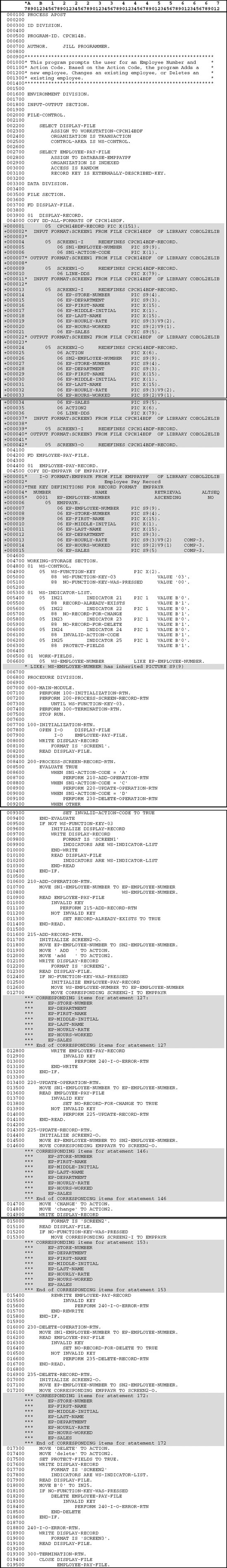
In this interactive file maintenance program, three record formats are used. Figure 14.29 illustrates the DDS for the display file. A description of the DDS follows the figure.

Record Format SCREEN1
File Level (Lines 7.00–10.00)
Line 7.00: The file-level keyword REF indicates that there are fields in this display file that are defined in the physical file EMPPAYPF.
Line 8.00: PRINT is usually defined as a file-level keyword. The PRINT keyword is used to enable the PRINT key function while the interactive program is running. This allows the user to print the current screen.
Line 9.00: The CA03 (03 'F3=Exit') line establishes a connection between F3 and the indicator 03 defined in the program. Since this line is defined at the file level, F3 is enabled for both SCREEN1 and SCREEN2 in the display file.
Line 10.00: The file-level keyword INDARA indicates that all indicators defined in the display file are passed to and from the program in a separate indicator area.
Record Level (Lines 12.00–13.00)
Line 12.00: This is the record format line that assigns a unique name (SCREEN1) to the record format.
Line 13.00: The BLINK keyword tells the system to blink the cursor when this record format is displayed.
Field Level (Lines 14.00–36.00)
Lines 14.00–19.00: These lines define line 1 of SCREEN1. Included are the USER profile name, the literal Employee File Maintenance, the program name and record format number (CPCH14B.1), and the system date.
Lines 20.00–21.00: Type value, press Enter is a literal that will appear on line 3 beginning in position 2.
Line 22.00–24.00: The Employee Number field, EMPLOYEENO, is left-justified in the Name field (positions 19–28). The file EMPPAYPF is referenced for the field's attributes. The letter D in the Data Type field (position 35) indicates that only the digits 0 through 9 are allowed as input into this field. This field has an ALIAS of SN1_EMPLOYEE_NUMBER.
The DSPATR keyword is used to specify two attributes for the EMPLOYEENO field. When used, the DSPATR keyword is placed on the same line as the field or constant, or the lines immediately following the field or constant, to which it applies. The attributes assigned to EMPLOYEENO are underline (UL) and high intensity (HI). Thus, when EMPLOYEENO appears on the screen, it will be underlined and will appear bold.
Lines 25.00–27.00: The ERRMSG keyword is associated with EMPLOYEENO so that additional information can be provided to the user when an error condition occurs. Line 25.00 identifies the error message that will appear when the user tries to add a record that is already in the file. When this happens, indicator 21 is set on and the error message Record already exists is sent back to the user.
When the user tries to change a record that is not in the file, indicator 22 is set on and the message No record for change is displayed on the screen. Likewise, if the user tries to delete a record not found in the file, indicator 23 is set on and the message No record for delete is displayed.
The keyword ERRMSG is followed by two parameters in parentheses. The first parameter, enclosed in apostrophes, is the error message that will appear on the message line if an error occurs. The second parameter is an optional indicator that is set off when the record format is read back into the program after the error condition is displayed. Thus, the conditioning indicator used to activate the ERRMSG keyword can be turned off when the record format is returned to the program.
Line 28.00–30.00: These lines define the caption, field, and error message for the action code field (SNACTCD). The caption and action code appears on line 7 beginning in position 5. Indicator 24 controls the error message. This means that if the user enters an invalid action code, the program sets on indicator 24, and an error message is returned back to the user on record format SCREEN1.
Lines 31.00–36.00: These lines provide information to the user.
Before we discuss record format SCREEN2, let us consider how data can be validated in an interactive application.
When writing a file maintenance program, one major concern for software developers is the prevention of invalid data from getting into database files. There are several techniques available that a software developer can employ to prevent such errors. For example, when writing a file maintenance program, procedures can be included in the program to verify that the data being entered by the user are correct. One example of this might be to verify that the hourly rate field contains a numeric value between $6.00 and $27.50. If the value in the hourly rate field is invalid, the interactive program would highlight the field and send an error message back to the user. Although this technique helps guarantee that the data being entered are correct, it makes for longer and more complex programs.
Another technique that can be used is to include validation keywords within the DDS for the database definition. That is, keywords are used in the DDS to explicitly indicate the data that can be placed in a particular field. For example, we could use the RANGE keyword in the DDS to indicate that the hourly rate field can only contain a range of values between $6.00 and $27.50. If the user tries to enter a value outside this range, the system will signal an error back to the user. For this technique to work however, the fields displayed in the record format must be the same field names defined in the database and be referenced back to them with the REF keyword.
Another technique employing the keyword concept is to place the keywords in the record formats of the display file. When this method is used and the record format is displayed on the screen, the system allows the user to enter data that meet the criteria of the keywords.
In record format SCREEN2 we illustrate four of the most common validation keywords. These keywords are used to place restrictions on what the user can enter into the fields. When the user enters a value that violates the keyword restriction, the system displays an appropriate error message on the message line (line 24). The message and the field that caused the error are automatically displayed in reverse image to bring attention to the user. The user must then reenter a new value. Figure 14.30 summarizes some of the most common keywords.

Record Format SCREEN2
Record Level (Lines 40.00–41.00)
Line 40.00: This is the record-format line for SCREEN2. Like all other record formats, the letter R in the Name Type field (position 17) identifies it. The name of the record, SCREEN2, is left-justified in the Name field (positions 19–28).
Line 41.00: The CA12(12 'F12=Cancel') line establishes a connection between the F12 and indicator 12. Since this line is defined at the record level, F12 is enabled for only SCREEN2.
Field Level (Lines 42.00–91.00)
Line 42.00: The USER profile name is displayed in the upper left of the screen.
Line 43.00: The SCREEN2 record format is used to add new records to the file and change or delete existing records that are in the file. This line defines an ACTION field into which the program will place ADD, CHANGE, or DELETE, depending upon which operation is taking place. This field will be displayed in high intensity (HI).
Line 44.00–48.00: Along with the action code on line 1 is the heading Employee File Maintenance, the program identification and record format number (CPCH14B.2), and the system date. These provide information to the user about the screen.
Line 49.00–51.00: These lines provide the caption and field definition for the Employee Number. Notice that the field is defined as output only. This prevents a user from trying to change the Employee Number on an update (change) operation. Since the Employee Number is the key to the file, it cannot be changed. To change an Employee Number, the employee record with the old employee number would have to be deleted and the new Employee Number would be added.
This field references back to the EMPPAYPF for its attributes. The alternative name SN2_EMPLOYEE_NUMBER is assigned to this field with the ALIAS keyword in position 45.
An EDTWRD keyword is specified to allow the Employee Number to appear with dashes.
Lines 52.00–57.00: These lines pertain to the STORENO field. In addition to the caption and field, there are three keywords. The DSPATR(PR) keyword is enabled for this input-capable field if indicator 25 is on. Indicator 25 is set on in the program during delete operations. This prevents the user from modifying this field when a delete operation is taking place. The DSPATR(PR) keyword is enabled (indicator 25 is on) for all SCREEN2 fields when a delete operation is being performed.
The VALUES keyword specifies what values are allowed in the STORENO field. If the user tries to enter a value not equal to 1133, 2257, 4464, 5003, 7315, or 8950 the system will issue an error and the user must enter a new value.
Lines 58.00–83.00: These lines define the remaining fields for SCREEN2. Notice the RANGE keyword for the hourly rate field. This states that the user must enter a value in the range 6.00 to 27.50. If the user enters a value outside this range, the system will respond with an error message and the user will have to enter a new value.
Some fields have EDTCDE keywords. Consider the EDTCDE(J $) for SALES. To allow a negative value to be displayed or entered into the SALES field, the edit code J is used. Also, when displayed the SALES field contains a floating dollar sign indicated by the $ in the EDTCDE keyword.
Lines 84.00–86.00: These lines produce a message on line 21 that tells the user which action is taking place. The program places into the ACTION2 field a value of add, change, or delete depending upon which procedure is being executed in the program.
Lines 87.00–91.00: These lines define literals that will appear on the screen to provide information to the user. F3 is pressed to Exit and terminate the program, while F12 allows the user to cancel the current operation. Pressing F12 cancels any data the user has input and returns the screen to the program.
Record Format SCREEN3
Unless special instructions are coded, only one record format is displayed on the screen at a time. Thus, when a record format is written to the workstation, the previous record format, if present, is erased.
In some situations, the software developer may want to overlay one record format with another. The record format for SCREEN3 illustrates the OVERLAY concept. The OVERLAY keyword is a record-level keyword that allows SCREEN3 to be written to the screen and overlay the record format that is currently on the screen.
When an input/output error occurs when trying to write to or read from the disk file, the record format SCREEN3 is used to communicate an error message to the user. When the error is displayed, it is displayed over the current screen.
Figure 14.31 illustrates the program that performs interactive maintenance on the employee pay file. Note how the MOVE CORRESPONDING statement is used to move data between the EMPLOYEE-PEY-FILE record format EMPPAYR and the display file record formats. Again, the shading represents coding copied to the program during the compile phase.
The instruction format for the MOVE CORRESPONDING is as follows.
Instruction Format

In the MOVE CORRESPONDING statement, all elementary items within group-item-1 that have the same names as corresponding elementary items in group-item-2 will be moved. Recall that a group item is a field or record that is subdivided into any number of elementary entries. Consider the following MOVE statement:
MOVE CORRESPONDING RECORD-IN TO RECORD-OUT.
With the MOVE CORRESPONDING statement, all fields in RECORD-IN that have the same names as fields in RECORD-OUT are moved. The same-named fields in RECORD-OUT need not be in any specific order. Any fields of the sending record, RECORD-IN, that are not matched by the same-named fields in the receiving record, RECORD-OUT, are ignored. As in all MOVE operations, the contents of sending fields remain unchanged.
Caution should be used with the MOVE CORRESPONDING because it is a potential source of error in programs when field-names are changed. However, the MOVE CORRESPONDING statement is a convenient method for moving data between the record format of the disk file and the record formats for the display file.
Batch processing occurs when transactions are gathered together and processed as a group during one complete job.
On-line, or interactive, processing refers to a system that provides immediate access to files, processes data immediately upon entry, and always keeps files up-to-date.
Display files
The iSeries 400 and AS/400 use display files as the interface between the user and the program.
Display files are defined externally from the program that uses them.
Display files are coded on data description specifications (DDS).
Types of record formats
A query, or informational, format provides information to the user.
The data entry format presents the user with a sequence of captioned fields that the user fills in with the required data.
A list panel or work with panel provides a method of displaying a subset of records on the screen.
Indicators, or switches, are used to communicate between the program and the display file. They can be used to (1) condition the attributes of a display file during the processing of an interactive program and (2) reflect function key responses that can control the processing of a program by relating function keys to indicators (switches) within the program.
Editing numeric fields
Most of the editing functions can be accomplished with the use of the EDTCDE (edit code) keyword.
The EDTWRD keyword is used to provide editing functions not available with EDTCDEs.
Programs written for interactive applications refer to this type of processing as WORKSTATION file processing.
1. Display file source members are defined as type DSPF.
2. A display file can contain one or more record formats.
3. Fields defined in a record format may be defined as input fields or output fields but cannot be defined as both input and output fields.
4. The best format for entering data is the informational format.
5. A list panel, or work with panel, can be used to display a specific group of records on the screen.
6. The DDS for a display file must be compiled before a program can use them.
7. Indicators can contain any value from 1 to 10.
8. Most editing functions can be accomplished with the use of the EDTWRD keyword.
9. The DFNATR keyword is used to define the attributes of an element in the record format.
10. Display files are coded on data description specifications.
When data are collected and held for later processing, this is a form of___processing.
When data are entered into a computer not connected to the main CPU and stored for future processing, this is called a(n)___operation.
With___processing, files are accessed and updated immediately, thus keeping files up-to-date at all times.
Updating files in an interactive environment is called a(n)___operation.
With___processing, every change to a file is entered and processed as it occurs.
When COBOL programs are written for interactive applications, the display file is called a(n)___
Most often,___are used in interactive processing to signal the user that an entry is required.
The___record format provides information to the user.
A(n)___on a screen provides a list of options from which the user can select the desired operation to be performed.
The___keyword allows one record format to display over another record format.
Explain the difference between batch processing and interactive processing.
Explain why indicators are needed in an interactive program.
Explain why it might be necessary to have more than one record format in a display file.
Describe the different types of display screens.
Using the problem definition shown below, write an interactive program to display a student's grades and his or her average. The record layout for the student grade file (STDGRDPF) is as follows.
Field Description | Type | Size |
|---|---|---|
Student Number | S | 5,0 |
Student Name | A | 20 |
Test #1 | P | 3,0 |
Test #2 | P | 3,0 |
Test #3 | P | 3,0 |
Test #4 | P | 3,0 |
Test #5 | P | 3,0 |
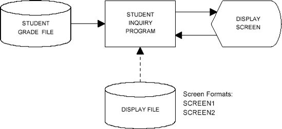
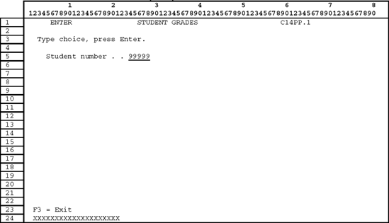
Format SCREEN1 (prompt user for student number)
Format SCREEN2 (view student record)
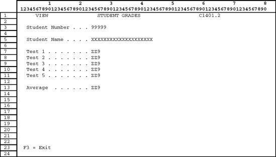
When SCREEN1 is displayed, the user enters a student number. The program reads SCREEN1 and tries to read the requested record from the student grade file. If a student record is requested that is not found in the student grade file, display the message Student record not found.
If the student number is found in the student grade file, format SCREEN2 is displayed, showing the five tests scores and the average. To terminate the program, the user presses F3.
Using the following problem definition, write an interactive program to inquire about individual records in the employee master file.
Record description layout for the employee master file
Field Description | Type | Size |
|---|---|---|
Employee Number | S | 5,0 |
Employee Name | A | 15 |
Employee Salary | P | 7,0 |

Format SCREEN1 (prompt user for employee number)

Format SCREEN2 (view employee record)

Format SCREEN1 is displayed on the screen to allow the user to enter the requested employee number. The program reads format SCREEN1 and tries to read the requested record from the employee master file. If an employee record is requested that is not found in the employee master file, the program displays the message Employee record not found. If the employee number is found in the employee master file, format SCREEN2 is displayed, showing the information from the employee record. To terminate the program, the user presses F3.
Perform the following steps for this assignment.
Complete DDS for the display file.
Create the display file source member.
Compile the display file into an object.
Code the program for this interactive program.
Enter and compile this program into an object.
Test the program.
Using the following problem definition, write an interactive program to add new employees to the employee salary file.
Record description layout for the employee salary file
Field Description
Type
Size
Employee Number
S
5,0
Employee Name
A
15
Employee Salary
P
7,0

Format SCREEN1 (enter new employee salary record)

Note: If the user tries to add an employee number that is already in the file, display the error message Employee record already exists.
Only one format is required in this interactive program. Format SCREEN1 is displayed on the screen with all fields blank and is used to prompt the user for the data needed to add a new employee to the employee salary file.
Upon processing format SCREEN1, the program will verify that the employee number does not already exist in the employee salary file. If the new employee number is found in the employee salary file, an error message is displayed to inform the user that the new employee number entered already exists in the file.
If the employee number is not found in the employee salary file, the new record is added. Format SCREEN1 is again displayed, and processing continues. The user terminates the program by pressing F3.
Using the following problem definition, write an interactive program to update the employee salary file with salary changes.
Record description layout for the employee salary file
Field Description
Type
Size
Employee Number
S
5,0
Employee Name
A
15
Employee Salary
P
7,0

Note: If an employee record is requested that is not found in the employee salary file, display the error message Employee record not found.
Design the two record formats necessary for this interactive program.
Format SCREEN1 is displayed on the screen to allow the user to enter the requested employee number. The program tries to retrieve the requested employee record from the file.
If the record is not found, an error message is displayed on the screen. If the employee number is found in the file, format SCREEN2 is displayed, showing the information from the employee record. The user would then enter the new salary for the employee and press the Enter key. The program reads format SCREEN2 and updates the employee record with the new salary. Once the transaction is completed, format SCREEN1 is displayed so that another employee record can be updated.
To terminate the program, the user presses F3.
Using the following problem definition, write an interactive program to perform file maintenance (additions, changes, and deletions) on a customer sales file.
Record description layout for a customer sales file
Field Description
Type
Size
Customer Number
S
5,0
Customer Name
A
15
Credit Rating
S
1,0
Date of Last Purchase
S
6,0
Year-to-date Sales
P
11,2
Outstanding Balance
P
9,2
For this assignment, complete all phases for the creation of the display file and coding of the program.
Write an interactive program to update the inventory file with orders that have been received. This interactive program allows the user to enter the warehouse number, product number, and quantity received. The program then retrieves the corresponding record from the inventory file and adds the quantity received to the Quantity on Hand field. The program also updates the Last Date Received field (yyyymmdd) with the current date.
Once the inventory file has been updated, the program reads the entire inventory file and produces a report of all products by warehouse that were received for the current date.
The record description layout for the inventory file is
Field Description | Type | Size |
|---|---|---|
Warehouse Number | S | 5,0 |
Product Number | S | 6,0 |
Quantity on Hand | P | 5,0 |
Last Date Received | L | 10 |