We now turn to the exciting subject of 3D graphics. As soon as we know how to compute the perspective image of a single point, we can easily produce more interesting images. To obtain the perspective image of a straight line, we simply connect the images of its endpoints, using the fact that the image of a straight line is also a straight line. In this chapter, the computation of the perspective image of a point is done in two steps: a viewing transformation followed by a perspective transformation.
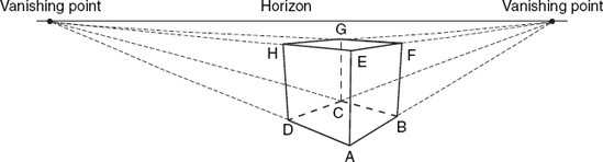
In Figure 5.1 a two-dimensional representation of a cube is shown along with some auxiliary lines. Although AB is a horizontal edge, it is not a horizontal line in the picture. Lines that in 3D space are horizontal and parallel meet in the picture in a so-called vanishing point. All these vanishing points lie on the same line, which is called the horizon. The horizon and vanishing points refer to the 2D image space, not to the 3D object space. For many centuries these concepts have been used by artists to draw realistic images of three-dimensional objects. This way of representing three-dimensional objects is usually referred to as perspective.
The invention of photography offered a new (and easier) way of producing images in perspective. There is a strong analogy between a camera used in photography and the human eye. Our eye is a very sophisticated instrument of which a camera is an imitation. In the following discussion the word eye may be replaced with camera if we want to emphasize that a two-dimensional hard copy is desired.
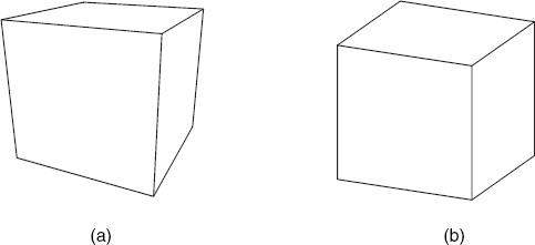
It is obvious that the image will depend upon the position of the eye. An important aspect is the distance between the eye and the object, since the effect of perspective will be inversely proportional to this distance. If the eye is close to the object, the effect of perspective is strong, as shown in Figure 5.2(a). Here we can very clearly see that in the image the extensions of parallel line segments meet.
Besides the classical and the photographic method, there is a way of producing perspective images which is based on analytical geometry. Let us write X and Y for 2D and x, y and z for 3D coordinates.
If we want to produce a drawing in perspective, we are given a great many points P(x, y, z) of the object and we want their images P′(X, Y) in the picture. Thus all we need is a mapping from the world coordinates (x, y, z) of a point P to the screen coordinates (X, Y) of its central projection P′. We imagine a screen between the object and the eye E. For every point P of the object the line PE intersects the screen at point P′. It is convenient to perform this mapping in two stages. The first is called a viewing transformation; point P is left at its place, but we change from world coordinates to so-called eye coordinates. The second stage is called a perspective transformation. This is a proper transformation from P to P′, combined with a transition from the three-dimensional eye coordinates to the two-dimensional screen coordinates:

To perform the viewing transformation we must be given not only an object but also a viewpoint E. Let us require that the world-coordinate system be right-handed. It is convenient if its origin O lies more or less centrally in the object; we then view the object from E to O. We will assume this to be the case; in practice this might require a coordinate transformation consisting of decreasing the original world coordinates by the coordinates of the central object point. We will include this very simple coordinate transformation in our program, without writing it down in mathematical notation.
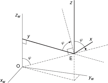
Let the viewpoint E be given by its spherical coordinates ρ(= rho), θ(= theta), φ(= phi), relative to the world-coordinate system. Thus its world-coordinates are

as shown in Figure 5.3.
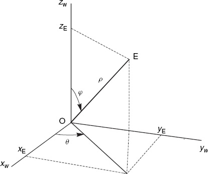
The direction of vector EO(= − OE) is said to be the viewing direction. From our eye at E we can only see points within some cone whose axis is EO and whose apex is E. If the Cartesian coordinates xE, yE, zE of viewpoint E were given, we could derive the spherical coordinates from them as follows:
rho = Math.sqrt(xE * xE + yE * yE + zE * zE);
theta = Math.atan2(yE, xE);
phi = Math.acos(zE/rho);
Our final objective will be to compute the screen coordinates X, Y, where we have an X-axis and a Y-axis, lying in a screen between E and O and perpendicular to the viewing direction EO. This is why the eye-coordinate system will have its xe-axis and ye-axis perpendicular to EO, leaving the ze-axis in the direction of OE. The origin of the eye-coordinate system is viewpoint E, as shown in Figure 5.4. Viewing from E to O, we find the positive xe-axis pointing to the right and the positive ye-axis upwards. These directions will enable us later to establish screen axes in the same directions. We could have used a positive ze-axis pointing from E to O; on the one hand this is attractive because it makes the ze-coordinates of all object points positive, but, on the other hand, it would have required a left-handed eye-coordinate system. In this book we will use a right-handed eye-coordinate system (as shown in Figure 5.4) to avoid confusion with regard to the use of the cross product, taking the minus sign of ze-coordinates into the bargain.

The viewing transformation can be written as a matrix multiplication, for which we need the 4 × 4 viewing matrix V:
To find V, we imagine this transformation to be composed of three elementary ones, for which the matrices can easily be written down. Matrix V will be the product of these three matrices. Each of the three transformations is in fact a change of coordinates and has therefore a matrix which is the inverse of the matrix for an equivalent point transformation.
(1) Moving the origin from O to E
We perform a translation of the coordinate system such that viewpoint E becomes the new origin. The matrix for this change of coordinates is

(Do not confuse xE, yE, zE, the world coordinates of viewpoint E, with xe, ye, ze, the eye coordinates of any point.) The new coordinate system is shown in Figure 5.5.

(2) Rotating the coordinate system about the z-axis
Starting with Figure 5.5 we rotate the coordinate system about the z-axis through the angle θ + 90°, so the new x-axis points to the right and is perpendicular to the vertical plane through E and O. The matrix for this change of coordinates is the same as that for a rotation of points through the angle −(θ + 90°), which equals −θ − 90°. We obtain the 4 × 4 matrix Rz for this rotation by including a 2 × 2 matrix, as discussed in Section 3.2, and adding the third and fourth columns and rows of a 4 × 4 unit matrix:
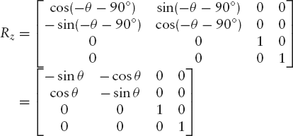
If you find the simplifications
| cos (– θ – 90°) = – sinθ and sin(–θ – 90°) = – cosθ |
difficult, it will be helpful to plot the two angles of this formula in a unit circle for some value of θ, as Figure 5.6 illustrates.

After applying the above matrix Rz, the new position of the x-, y- and z-axes is as shown in Figure 5.7.
(3) Rotating the coordinate system about the x-axis
Since the z-axis is to have the direction OE, we now rotate the coordinate system about the x-axis through the angle φ. The dashed line near the positive z-axis in Figure 5.7 indicates the new y-axis after this rotation. A rotation about the x-axis is said to be positive if the y-axis goes towards the z-axis (through an angle of 90°). It corresponds to the turning of a normal, right-handed screw which moves forward in the direction of the positive x-axis. However, since we are performing a coordinate transformation instead of rotating points, we have to use −φ instead of φ as the angle of rotation, so that we obtain the following rotation matrix:

After this final rotation, we have obtained the eye-coordinate system with xe-, ye- and ze-axes, which we have already seen in Figure 5.4. Multiplying the above matrices T, Rz and Rx, we obtain the desired viewing matrix:

Recall that we use this matrix in Equation (5.2), to compute the eye coordinates xe, ye and ze from the given world coordinates xw, yw and zw.
The viewing transformation described above is to be followed by the perspective transformation to be discussed in the next section. However, we could also use the eye coordinates xe and ye, simply ignoring ze. In that case we have a so-called orthographic projection. Every point P of the object is then projected into a point P′ by drawing a line from P, perpendicular to the plane through the x-axis and the y-axis. It can also be regarded as the perspective image we obtain if the viewpoint is infinitely far away. An example of such a picture is the cube in Figure 5.2(b). Parallel lines remain parallel in pictures obtained by orthographic projection. Such pictures are very often used in practice because with conventional methods they are easier to draw than real perspective images.
On the other hand, bringing some perspective into the picture will make it much more realistic. Our viewing transformation will therefore be followed by the perspective transformation, which will involve surprisingly little computation.
You might have the impression that we are only half-way, and that in this section we will need as much mathematics as in Section 5.2. However, most of the work has already been done. Since we will not use world coordinates in this section, there will be no confusion if we denote eye coordinates simply by (x, y, z) instead of (xe, ye, ze).
In Figure 5.8 we have chosen a point Q, whose eye coordinates are (0, 0, –d) for some positive value d.

Our screen will be the plane z = –d, that is, the plane through Q and perpendicular to the z-axis. Then the screen-coordinate system has Q as its origin, and its X- and Y-axes are parallel to the x- and y-axes. For every object point P, the image point P′ is the intersection of line PE and the screen. To keep Figure 5.8 simple, we consider a point P whose y-coordinate is zero. However, the following equations to compute its screen coordinate X are also valid for other y-coordinates. In Figure 5.8 the triangles EPR and EP′Q are similar. Hence

so we have
(Recall that z-coordinates of object points are negative, so that –z is a positive value.) In other words,
In the same way we can derive
At the beginning of Section 5.2 we chose the origin O of the world-coordinate system to be a central point of the object. The origin Q of the screen-coordinate system will be central in the image because the z-axis of the eye-coordinate system is a line through E and O, which intersects the screen at Q. We must bear in mind that Equations (5.7) and (5.8) can be used in this form only if the origin Q of the screen coordinate system (with X- and Y-axes) lies in the center of the screen. If this origin lies instead in the lower-left corner of the screen and the screen has width w and height h, we have to add w/2 and h/2 to the Equations (5.7) and (5.8), respectively.

We still have to specify the distance d between viewpoint E and the screen. Roughly speaking, we have
which follows from the similarity of the triangles EP′1P′2 and EP1P2 in Figure 5.9. Thus we have
This equation should be applied to both the horizontal and the vertical directions. It should be interpreted only as a means to obtain an indication about an appropriate value for d, for the three-dimensional object may have a complicated shape, and it may not be clear how its size is to be measured. We then use a rough estimation of the object size, such as the maximum of its length, width and height. The image size in Equation (5.9) should be taken somewhat smaller than the screen.
We will now discuss a complete Java program, which draws a perspective representation of a cube, as shown in Figure 5.10. Such representations, with all edges visible, are called wire-frame models.
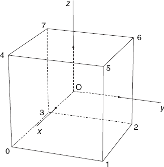
To specify this cube in a program, we assign numbers to its vertices, as shown in Figure 5.11. The center of the cube coincides with the origin O and its edges have length 2, which implies that the x-, y- and z-coordinates of its eight vertices are equal to +1 or −1.

The following program produces the wire-frame model of Figure 5.10. We store the world, eye and screen coordinates for each of the eight vertices of the cube in the class Obj:
// CubePers.java: A cube in perspective.
// Uses: Point2D (Section 1.5), Point3D (Section 3.9).
import java.awt.*;
import java.awt.event.*;

public class CubePers extends Frame
{  public static void main(String[] args){new CubePers();}

   CubePers()
   {  super("A cube in perspective");
      addWindowListener(new WindowAdapter()
         {public void windowClosing(WindowEvent e){System.exit(0);}});
      setLayout(new BorderLayout());
      add("Center", new CvCubePers());
      Dimension dim = getToolkit().getScreenSize();
      setSize(dim.width/2, dim.height/2);
      setLocation(dim.width/4, dim.height/4);
      show();
   }
}

class CvCubePers extends Canvas
{  int centerX, centerY;
   Obj obj = new Obj();

   int iX(float x){return Math.round(centerX + x);}
   int iY(float y){return Math.round(centerY - y);}

   void line(Graphics g, int i, int j)
   {  Point2D p = obj.vScr[i], q = obj.vScr[j];
      g.drawLine(iX(p.x), iY(p.y), iX(q.x), iY(q.y));
   }

   public void paint(Graphics g)
   {  Dimension dim = getSize();
      int maxX = dim.width - 1, maxY = dim.height - 1,
          minMaxXY = Math.min(maxX, maxY);
      centerX = maxX/2; centerY = maxY/2;
      obj.d = obj.rho * minMaxXY / obj.objSize;
      obj.eyeAndScreen();
      // Horizontal edges at the bottom:
      line(g, 0, 1); line(g, 1, 2); line(g, 2, 3); line(g, 3, 0);
      // Horizontal edges at the top:
      line(g, 4, 5); line(g, 5, 6); line(g, 6, 7); line(g, 7, 4);
      // Vertical edges:
line(g, 0, 4); line(g, 1, 5); line(g, 2, 6); line(g, 3, 7);
}
}
class Obj // Contains 3D object data
{ float rho, theta=0.3F, phi=1.3F, d, objSize,
v11, v12, v13, v21, v22, v23, v32, v33, v43;
// Elements of viewing matrix V
Point3D[] w; // World coordinates
Point2D[] vScr; // Screen coordinates
Obj()
{ w = new Point3D[8];
vScr = new Point2D[8];
// Bottom surface:
w[0] = new Point3D( 1, −1, −1);
w[1] = new Point3D( 1, 1, −1);
w[2] = new Point3D(−1, 1, −1);
w[3] = new Point3D(−1, −1, −1);
// Top surface:
w[4] = new Point3D( 1, −1, 1);
w[5] = new Point3D( 1, 1, 1);
w[6] = new Point3D(−1, 1, 1);
w[7] = new Point3D(−1, −1, 1);
objSize = (float)Math.sqrt (12F);
// = sqrt(2 * 2 + 2 * 2 + 2 * 2)
// = distance between two opposite vertices.
rho = 5 * objSize; // For reasonable perspective effect
}
void initPersp()
{ float costh = (float)Math.cos(theta),
sinth = (float)Math.sin(theta),
cosph = (float)Math.cos(phi),
sinph = (float)Math.sin(phi);
v11 = -sinth; v12 = -cosph * costh; v13 = sinph * costh;
v21 = costh; v22 = -cosph * sinth; v23 = sinph * sinth;
v32 = sinph; v33 = cosph;
v43 = -rho;
}
void eyeAndScreen()
{ initPersp();
for (int i=0; i<8; i++){ Point3D p = w[i];
float x = v11 * p.x + v21 * p.y,
y = v12 * p.x + v22 * p.y + v32 * p.z,
z = v13 * p.x + v23 * p.y + v33 * p.z + v43;
vScr[i] = new Point2D(-d * x/z, -d * y/z);
}
}
}As discussed in Section 5.3 (see point Q in Figure 5.8), the perspective transformation is simplest if we use a coordinate system with the origin in the center of the screen and with a y-axis pointing upward. To convert such (floating-point) coordinates to device coordinates of type int, we again use the methods iX and iY. As usual, these are based on the values of the fields centerX, centerY and maxY, which are computed in the paint method before this method uses iX and iY.
The paint method also computes the screen distance d (stored in obj), using Equation (5.9). After calling the Obj method eyeAndScreen to compute eye and screen coordinates, we use our method line to draw all 12 cube edges.
In the class Obj, the arrays w and vScr contain the world and the screen coordinates, respectively, of the cube vertices. Recall that we use the matrix multiplication of Equation (5.2) to compute the eye coordinates from the given world coordinates stored in w. We then use these eye coordinates to compute the screen coordinates for the array vScr. Figure 5.11 is helpful in specifying the coordinate values in the array w and the vertex numbers in calls to the line method.
To avoid duplication of code, we now present some classes (Input, Obj3D, Tria, Polygon3D, Canvas3D and Fr3D) that we will frequently use later.
The first class we will discuss is Input. It is not really specific for computer graphics, but useful for any programming task that involves reading data from a textfile in a simple way. We will use it to read data for 3D objects, specified in a particular format. There is an Input constructor that accepts the name of an input file as an argument, as well as a constructor without any arguments to read data from the keyboard. To demonstrate how easy it is to use this class, let us suppose we are given a textfile containing only numbers and we want to write a program to read this file and compute the sum of these numbers. For example, this textfile, say, example.txt, may have the following contents:
2.5     6
200     100
Then the desired program is shown below:
// Sum.java: Demonstrating the class Input by computing the sum
//   of all numbers in the textfile example.txt (which contains
//   only numbers and whitespace characters).
public class Sum
{  public static void main(String[] args)
   {  float x, s=0;
      Input inp = new Input("example.txt");
      for (;;)
      {  x = inp.readFloat();
         if (inp.fails())
            break;
         s += x;
      }
      System.out.println("The computed sum is " + s);
   }
}
After compiling and executing this program in a directory that also contains the files Input.java and example.txt, the following output line is displayed:
The computed sum is 308.5
This example demonstrates the use of the Input constructor and of the methods readFloat and fails. The complete class Input, listed below, shows that it contains some other useful methods as well:
// Input.java: A class to read numbers and characters from textfiles.
// Methods of this class, available for other program files:
//   Input(fileName) (constructor; open input file)
//   Input()         (constructor; prepare for input from keyboard)
//   readInt()       (read an integer)
//   readFloat()     (read a float number)
//   readChar()      (read a character)
//   readString()    (read a string between double quotes)
//   skipRest()      (skip all remaining characters of current line)
//   fails()         (input operation failed)
//   eof()           (failure because of end of file)
//   clear()         (reset error flag)
//   close()         (close input file)
//   pushBack(ch)    (push character ch back into the input stream)
import java.io.*;

class Input
{  private PushbackInputStream pbis;
   private boolean ok = true;
   private boolean eoFile = false;

   Input(){pbis = new PushbackInputStream(System.in);}

   Input(String fileName)
   {  try
      {  InputStream is = new FileInputStream(fileName);
         pbis = new PushbackInputStream(is);
      }
      catch(IOException ioe){ok = false;}
   }

   int readInt()
   {  boolean neg = false;
      char ch;
      do {ch = readChar();}while (Character.isWhitespace(ch));
      if (ch == '-') neg = true; ch = readChar();}
      if (!Character.isDigit(ch))
      {  pushBack(ch);
         ok = false;
         return 0;
      }
      int x = ch - '0';
      for (;;)
      {  ch = readChar();
         if (!Character.isDigit(ch)){pushBack(ch); break;}
         x = 10 * x + (ch - '0'),
      }
      return (neg ? -x : x);
   }
float readFloat()
{ char ch;
int nDec = −1;
boolean neg = false;
do
{ ch = readChar();
} while (Character.isWhitespace(ch));
if (ch == '-'){neg = true; ch = readChar();}
if (ch == '.'){nDec = 1; ch = readChar();}
if (!Character.isDigit(ch)){ok = false; pushBack(ch); return 0;}
float x = ch - '0';
for (;;)
{ ch = readChar();
if (Character.isDigit(ch))
{ x = 10 * x + (ch - '0'),
if (nDec >= 0) nDec++;
}
else
if (ch == '.' && nDec == −1) nDec = 0;
else break;
}
while (nDec > 0){x *= 0.1; nDec--;}
if (ch == 'e' || ch == 'E')
{ int exp = readInt();
if (!fails())
{ while (exp < 0){x *= 0.1; exp++;}
while (exp > 0){x *= 10; exp--;}
}
}
else pushBack(ch);
return (neg ? -x : x);
}
char readChar()
{ int ch=0;
try
{ ch = pbis.read();
if (ch == −1) {eoFile = true; ok = false;}
}
catch(IOException ioe){ok = false;
return (char)ch;
}String readString() // Read first string between quotes (").
{ String str = " ";
char ch;
do ch = readChar(); while (!(eof() || ch == '"'));
// Initial quote
for (;;)
{ ch = readChar();
if (eof() || ch == '"') // Final quote (end of string)
break;
str += ch;
}
return str;
}
void skipRest() // Skip rest of line
{ char ch;
do ch = readChar(); while (!(eof() || ch == '
'));
}
boolean fails(){return !ok;}
boolean eof(){return eoFile;}
void clear(){ok = true;}
void close()
{ if (pbis != null)
try {pbis.close();}catch(IOException ioe){ok = false;}
}
void pushBack(char ch)
{ try {pbis.unread(ch);}catch(IOException ioe){}
}
}Using a call to readChar immediately after readInt or readFloat causes the character immediately after the number to be read. To realize this, we use the standard Java class PushbackInputStream, which enables us to push back, or 'unread' the last character that we have read and that does not belong to the number we are reading.
After an attempt to read a number by using readInt or readFloat, we can call the fails method to check whether that attempt was successful. If fails returns true, a non-numeric character, such as a period in the second part of our input files, may have been read. It is then still possible to read that character by using readChar. The clear method resets the error flag, so that we can resume input, using fails again. The method fails also returns true if an input operation fails because the end of the file is encountered during a call to one of the methods readInt, readFloat and readChar. In that case, the eof method also returns true. We can use the method readString to read a string surrounded by double quotes ("), as we will do in Chapter 8. To skip all remaining characters of the current input line, we use the method skipRest.
Let us now discuss the way the above class Input is used in the method readObject of the class Obj3D. Suppose we have an input file such as the one shown below:
1    0    0      0
2    0  100.5    0
3    0    0    1.5e2
Faces:
1 2 3.
3 2 1.
We will often use files of this type, which will be described in more detail in the next chapter. This example defines a 3D object that has only three vertices, with numbers 1, 2 and 3. The x-, y- and z-coordinates are given after each of these vertex numbers. The object has two faces, which are the two sides of the triangle with these three vertices. The first line following the word Faces indicates the side where we view the vertices 1, 2 and 3, in that order, counter-clockwise, while the last line denotes the other side. Obviously, which of these two triangle sides we can see depends on the point of view.
A simplified version of the Obj3D method readObject is shown below. It shows how the class Input can be used to read data files such as the one shown above. In this fragment three dots (. . .) denote code that is not relevant in this discussion because it does not perform any input operations:
private boolean readObject(Input inp)
{  for (;;)
   { int i = inp.readInt();
     if (inp.fails()){inp.clear(); break;}
     ...
     float x = inp.readFloat(),
           y = inp.readFloat(),
           z = inp.readFloat();
addVertex(i, x, y, z);
}
...
do // Skip the line "Faces:"
{ ch = inp.readChar(); count++;
} while (!inp.eof() && ch != '
'),
...
// Build polygon list:
for (;;)
{ Vector vnrs = new Vector();
for (;;)
{ int i = inp.readInt();
if (inp.fails()){inp.clear(); break;}
...
vnrs.addElement(new Integer(i));
}
ch = inp.readChar();
if (ch != '.') break;
// Ignore input lines with only one vertex number:
if (vnrs.size() >= 2)
polyList.addElement(new Polygon3D(vnrs));
}
inp.close();
return true;
}The above fragment is a simplified version of the method readObject of the class Obj3D, which we will now discuss in more detail. We will use this class to store all data of 3D objects, along with their 2D representations, in such a way that this data is easy to use in our programs. We store three representations of vertices:
'Vector' w of Point3D elements: | world coordinates |
Array e of Point3D elements: | eye coordinates |
Array vScr of Point2D elements: | screen coordinates |
Recall the classes Point2D and Point3D discussed in Sections 1.5 and 3.9. Since we read the world coordinates from an input file without knowing in advance how many vertices there will be, we use a Java Vector for them. This is different with the eye and screen coordinates. Since we compute these ourselves after we have read the world coordinates of all vertices, we know the size of the arrays e and vScr, so that we can allocate memory for them. We use the vertex numbers to indicate the positions in w, e, and vScr. In other words, with an input line of the form
| i x y z |
we can find these world coordinates x, y and z of vertex i in the Point3D object
(Point3D)w.elementAt(i)
We use the Obj3D method eyeAndScreen to compute the corresponding eye coordinates and store them in the Point3D object
e[i]
This method also computes the corresponding screen coordinates and stores them in the Point2D object
vScr[i]
It follows that w.size(), e.length and vScr.length will be one higher than the highest vertex number that is in use.
We will use the accessor methods getE() and getVScr() for access to the arrays e and vScr. The Vector object w will not be used at all outside the class Obj3D.
Another useful method of Obj3D is planeCoeff. For each face (or polygon) of the object, it computes the coefficients a, b, c and h of the equation
which describes the plane where this face lies. Using the first three vertices A, B and C of a polygon, we compute the normal vector n = (a, b, c) of the plane as the vector product AB × AC (see Section 2.4), scaled such that
| a2 + b2 + c2 = 1 |
Using the inner product (see Section 2.2) of n and a vector x = EP for any point P in the plane, we can write (5.10) as
| n · x = h |
in which h is positive if the sequence A, B and C is clockwise, that is, if ABC is a back face. On the other hand, if ABC is not a back face, h is negative and the sequence A, B and C is counter-clockwise. Recall that the positive z-axis (in the eye-coordinate system) points towards us, as is more or less the case with the normal vector n of a visible face. However, the vector x points away from us, which implies that the inner product n · x = h will be negative for a visible face and positive for a back face. The absolute value of h is the distance between the eye E and the plane in question (see Exercise 7.1). We will use the coefficients a, b, c and h on several occasions. In the class Obj3D, the method planeCoeff computes these coefficients, after which they are stored in Polygon3D objects, as we will see shortly. This method planeCoeff also computes the maximum and minimum values of an inner product used to determine which color is to be assigned to each face, as we will discuss in Section 7.2.
Since the file Obj3D.java is considerably larger than the program files we have seen so far, it is not listed here but you can find it in Appendix C. Here is a summary of all methods of this class that we can use outside it:
boolean read(String fName) // Reads a 3D object file, if possible.
Vector getPolyList()       // Returns polyList, the list of faces.
String getFName()          // File name of current object.
Point3D[] getE()           // Eye coordinates e of vertices.
Point2D[] getVScr()        // Screen coordinates vScr of vertices.
Point2D getImgCenter()     // Center of image in screen coordinates.
float getRho()             // Rho, the viewing distance.
float getD()               // d, scaling factor, also screen distance.
float eyeAndScreen         // Computes eye and screen coordinates and
                           // returns maximum screen-coordinate range.
void planeCoeff()          // Computes the coefficients a, b, c, h
                           // for all faces.
boolean vp(Canvas cv, float dTheta, float dPhi, float fRho)
                           // Changes the viewpoint.
int colorCode(double a, double b, double c)
                           // Computes the color code of a face.
We will discuss the method colorCode in detail in Section 7.2. The public Obj3D method read calls the private method readObject, discussed above, as the following fragment shows:
boolean read(String fName)
{  Input inp = new Input(fName);
   ...
   return readObject(inp); // Read from inp into obj
}
As we have seen in the simplified version of readObject, this method starts by repeatedly reading four numbers, i, x, y and z, and calls the method addVertex, which keeps track of the minimum and maximum values of x, y and z. The loop in which the four numbers are read terminates when an attempt to read a vertex number i fails because of the word Faces. The minimum and maximum coordinate values just mentioned are required for a call to the private method shiftToOrigin, which reduces all world coordinates such that the origin of the coordinate center will coincide with the center of the bounding box of the object.
After skipping the rest of the line on which we encounter the word Faces, we enter a loop to read vertex-number sequences representing polygons. Vertex numbers in these sequences may be preceded by a minus sign, as we will discuss in Chapter 6, so that the vertex numbers are actually the absolute values of the integers that we read.
Since we will often refer to the class Obj3D, let us have a look at a simplified version of it:
// Obj3D.java: A 3D object and its 2D representation.
// Uses: Point2D (Section 1.5), Point3D (Section 3.9),
//       Polygon3D, Input (Section 5.5).
...
class Obj3D
{  ...
   private Vector w = new Vector();        // World coordinates
   private Point3D[] e;                    // Eye coordinates
   private Point2D[] vScr;                 // Screen coordinates
   private Vector polyList = new Vector(); // Polygon3D objects
   ...
   private void addVertex(int i, float x, float y, float z)
   {  ...
   }
   ...
}
Recall that the complete version is listed in Appendix C.
We will often store large sets of triangles, the vertices of which have numbers in the same way as letters normally used in geometry. Since several triangles may share some vertices, it would not be efficient to store the coordinates of each vertex separately for every triangle. For example, suppose in 3D space we have a triangle with vertices 1, 2 and 3 and another with vertices 1, 4 and 2. It will then be efficient to set up a table with the x-, y- and z-coordinates of the four vertices 1, 2, 3 and 4, and denote the triangles only by their vertex numbers. The following class represents triangles in this way:
// Tria.java: Triangle represented by its vertex numbers.
class Tria
{  int iA, iB, iC;
   Tria(int i, int j, int k){iA = i; iB = j; iC = k;}
}
If there had been no 3D programs in this book other than that for wire-frame models, as discussed in Section 5.6, it would not have been necessary to store polygons, let alone triangles. We could then have restricted ourselves to the edges of 3D objects, that is, to line segments. We will nevertheless store the polygonal faces of the objects even in this chapter, to prepare for some more interesting programs where hidden lines or faces are not displayed.
Almost at the end of the Obj3D method readObject you may have noticed the following statement:
polyList.addElement(new Polygon3D(vnrs));
Here a new Polygon3D object is created to store the vertex numbers of a polygon. This object is then added to the Vector object polyList, a private variable of the class Obj3D. The class Polygon3D contains a number of methods that we will not use in this chapter. These are related to triangles resulting from polygons and will be useful in the next two chapters, in which we will be dealing with algorithms to eliminate hidden lines and faces. Thanks to the above class Tria, the coordinates of the vertices of each triangle are not duplicated. Since they are stored in arrays that are data members of the Obj3D class, we only need to store the numbers iA, iB and iC of the vertices here. Although, in Section 2.13, we have already used a method triangulate to divide a polygon into triangles, we will need a slightly different one that represents vertices by numbers referring to the Obj3D class. This special method for triangulation is part of the class Polygon3D, listed below:
// Polygon3D.java: Polygon in 3D, represented by vertex numbers
//                 referring to coordinates stored in an Obj3D object.
import java.util.*;
class Polygon3D
{  private int[] nrs;
   private double a, b, c, h;
   private Tria[] t;
   Polygon3D(Vector vnrs)
   {  int n = vnrs.size();
      nrs = new int[n];
      for (int i=0; i<n; i++)
         nrs[i] = ((Integer)vnrs.elementAt(i)).intValue();
   }

   int[] getNrs(){return nrs;}
   double getA(){return a;}
   double getB(){return b;}
   double getC(){return c;}
   double getH(){return h;}
   void setAbch(double a, double b, double c, double h)
   {  this.a = a; this.b = b; this.c = c; this.h = h;
   }
   Tria[] getT(){return t;}

   void triangulate(Obj3D obj)
   // Successive vertex numbers (CCW) in vector nrs.
   // Resulting triangles will be put in array t.
   {  int n = nrs.length;         // n > 2 is required
      int[] next = new int[n];
      t = new Tria[n − 2];
      Point2D[] vScr = obj.getVScr();
      int iA=0, iB, iC;
      int j = n − 1;
      for (int i=0; i<n; i++){next[j] = i; j = i;}
      for (int k=0; k<n-2; k++)
      {  // Find a suitable triangle, consisting of two edges
        // and an internal diagonal:
         Point2D a, b, c;
         boolean found = false;
         int count = 0, nA = −1, nB = 0, nC = 0, nj;
         while (!found && ++count < n)
         {  iB = next[iA]; iC = next[iB];
            nA = Math.abs(nrs[iA]); a = vScr[nA];
            nB = Math.abs(nrs[iB]); b = vScr[nB];
            nC = Math.abs(nrs[iC]); c = vScr[nC];
if (Tools2D.area2(a, b, c) >= 0)
{ // Edges AB and BC; diagonal AC.
// Test to see if no vertex (other than A,
// B, C) lies within triangle ABC:
j = next[iC]; nj = Math.abs(nrs[j]);
while (j != iA &&
(nj == nA || nj == nB || nj == nC ||
!Tools2D.insideTriangle(a, b, c, vScr[nj])))
{ j = next[j]; nj = Math.abs(nrs[j]);
}
if (j == iA)
{ // Triangle found:
t[k] = new Tria(nA, nB, nC);
next[iA] = iC;
found = true;
}
}
iA = next[iA];
}
if (count == n)
{ // Degenerated polygon, possibly with all
// vertices on one line.
if (nA >= 0) t[k] = new Tria(nA, nB, nC);
else
{ System.out.println("Nonsimple polygon");
System.exit(1);
}
}
}
}
}The vertex numbers of the given polygon are available in the array nrs, while those of each resulting triangle are stored in an element of the array t. The most difficult part of this class is the method triangulate, which is the 3D equivalent of the Tools2D method with the same name, discussed in Section 2.13 and not used in this chapter.
The canvas classes we will be using will contain the methods getObj and setObj, to retrieve and store a reference to an Obj3D object. In view of a separate frame class, Fr3D, we need to define the following abstract class:
// Canvas3D.java: Abstract class.
import java.awt.*;

abstract class Canvas3D extends Canvas
{  abstract Obj3D getObj();
   abstract void setObj(Obj3D obj);
}
Remember, abstract classes are only useful to create subclasses, not to define objects. Any (non-abstract) subclass of Canvas3D is simply a subclass of the standard class Canvas, except that it is guaranteed to define the methods getObj and setObj. For example, in the next section we will discuss a class CvWireframe of which the first line reads
class CvWireframe extends Canvas3D
By writing here Canvas3D instead of Canvas, we are obliged to define the methods getObj and setObj in this CvWireframe class, and in return we are allowed to call these two methods for any object of class CvWireframe. We will clarify the use of the abstract class Canvas3D further at the end of this section.
The class Fr3D will be used in four non-trivial 3D programs of this book, Wireframe.java (Section 5.6), HLines.java (Chapter 6), Painter.java (Section 7.3) and ZBuf.java (Section 7.4). Since these programs will have the same menus, it makes sense to let them share the file Fr3D.java, listed below, in which much of the code is related to these menus. The Java compiler accepts the calls cv.getObj() and cv.setObj(obj) in this file because, as Canvas3D is an abstract class, the actual type of cv can only be a subclass of it. As we have just seen, this implies that this subclass will define the methods getObj and setObj:
// Fr3D.java: Frame class to deal with menu commands and other
//    user actions.
import java.awt.*;
import java.awt.event.*;
import java.util.*;

class Fr3D extends Frame implements ActionListener
{  protected MenuItem open, exit, eyeUp, eyeDown, eyeLeft, eyeRight,
      incrDist, decrDist;
   protected String sDir;
protected Canvas3D cv;
protected Menu mF, mV;
Fr3D(String argFileName, Canvas3D cv, String textTitle)
{ super(textTitle);
addWindowListener(new WindowAdapter()
{public void windowClosing(WindowEvent e){System.exit(0);}});
this.cv = cv;
MenuBar mBar = new MenuBar();
setMenuBar(mBar);
mF = new Menu("File");
mV = new Menu("View");
mBar.add(mF); mBar.add(mV);
open = new MenuItem("Open",
new MenuShortcut(KeyEvent.VK_O));
eyeDown = new MenuItem("Viewpoint Down",
new MenuShortcut(KeyEvent.VK_DOWN));
eyeUp = new MenuItem("Viewpoint Up",
new MenuShortcut(KeyEvent.VK_UP));
eyeLeft = new MenuItem("Viewpoint to Left",
new MenuShortcut(KeyEvent.VK_LEFT));
eyeRight = new MenuItem("Viewpoint to Right",
new MenuShortcut(KeyEvent.VK_RIGHT));
incrDist = new MenuItem("Increase viewing distance",
new MenuShortcut(KeyEvent.VK_INSERT));
decrDist = new MenuItem("Decrease viewing distance",
new MenuShortcut(KeyEvent.VK_DELETE));
exit = new MenuItem("Exit",
new MenuShortcut(KeyEvent.VK_Q));
mF.add(open); mF.add(exit);
mV.add(eyeDown); mV.add(eyeUp);
mV.add(eyeLeft); mV.add(eyeRight);
mV.add(incrDist); mV.add(decrDist);
open.addActionListener(this);
exit.addActionListener(this);
eyeDown.addActionListener(this);
eyeUp.addActionListener(this);
eyeLeft.addActionListener(this);
eyeRight.addActionListener(this);
incrDist.addActionListener(this);
decrDist.addActionListener(this);add("Center", cv);
Dimension dim = getToolkit().getScreenSize();
setSize(dim.width/2, dim.height/2);
setLocation(dim.width/4, dim.height/4);
if (argFileName != null)
{ Obj3D obj = new Obj3D();
if (obj.read(argFileName)){cv.setObj(obj); cv.repaint();}
}
cv.setBackground(new Color (180, 180, 255) );
show();
}
void vp(float dTheta, float dPhi, float fRho) // Viewpoint
{ Obj3D obj = cv.getObj();
if (obj == null || !obj.vp(cv, dTheta, dPhi, fRho))
Toolkit.getDefaultToolkit().beep();
}
public void actionPerformed(ActionEvent ae)
{ if (ae.getSource() instanceof MenuItem)
{ MenuItem mi = (MenuItem)ae.getSource();
if (mi == open)
{ FileDialog fDia = new FileDialog(Fr3D.this,
"Open", FileDialog.LOAD);
fDia.setDirectory(sDir);
fDia.setFile("*.dat");
fDia.show();
String sDir1 = fDia.getDirectory();
String sFile = fDia.getFile();
String fName = sDir1 + sFile;
Obj3D obj = new Obj3D();
if (obj.read(fName))
{ sDir = sDir1;
cv.setObj(obj);
cv.repaint();
}
}
else
if (mi == exit) System.exit(0); else
if (mi == eyeDown) vp(0, .1F, 1); else
if (mi == eyeUp) vp(0, -.1F, 1); else
if (mi == eyeLeft) vp(-.1F, 0, 1); else
if (mi == eyeRight) vp(.1F, 0, 1); elseif (mi == incrDist) vp (0, 0, 2); else
if (mi == decrDist) vp(0, 0, .5F);
}
}
}Notice the use of the abstract class Canvas3D in the line
Fr3D(String argFileName, Canvas3D cv, String textTitle)
almost at the beginning of class Fr3D. We cannot replace Canvas3D with Canvas here because the compiler would not accept the statement
cv.setObj(obj);
in the if-statement near the end of the Fr3D constructor. After all, setObj is not a method of the standard Java class Canvas. Since, in the next section we will actually be using the class CvWireframe, of which setObj is really a method, it is tempting to write CvWireframe instead of Canvas3D. This would indeed work, but then we would not be able to use the class Fr3D also in programs with canvas classes other than CvWireframe, as we will do in Chapters 6 and 7. We now see that the abstract class Canvas3D is very useful. It is general enough to be used in several of our programs and yet less general than the standard Canvas class in that it 'promises' an implementation of the methods setObj and getObj. We will discuss some aspects of the class Fr3D in Chapter 7 when using it.
It is now time to see the classes of the previous section in action. A relatively simple way of displaying 3D objects, bounded by polygons, is by drawing all the edges of these polygons, as we did for a cube in Section 5.4. The classes we have just seen enable us to write a general program Wireframe.java, which reads input files through a menu command Open and enables the user to view the object from any reasonable viewpoint, by using either menu commands or the keyboard. The comment lists all classes that Wireframe.java directly or indirectly uses.
// Wireframe.java: Perspective drawing using an input file that lists
//    vertices and faces.
// Uses: Point2D (Section 1.5),
//       Triangle, Tools2D (Section 2.13),
//       Point3D (Section 3.9),
//       Input, Obj3D, Tria, Polygon3D, Canvas3D, Fr3D (Section 5.5),
//       CvWireframe (Section 5.6).
import java.awt.*;

public class Wireframe extends Frame
{  public static void main(String[] args)
   {  new Fr3D(args.length > 0 ? args[0] : null, new CvWireframe(),
        "Wire-frame model");
   }
}
This rather simple program file accepts an optional program argument, which may be supplied to specify the name of the input file. This is what the first argument, a conditional expression, of the Fr3D constructor is about. The second argument of this constructor generates an object of class CvWireframe, which does almost all the work. Finally, the third argument specifies the text, Wire-frame model, that we want to appear in the title bar of the window. The class CvWireframe is listed below:
// CvWireframe.java: Canvas class for class Wireframe.
import java.awt.*;
import java.util.*;

class CvWireframe extends Canvas3D
{  private int maxX, maxY, centerX, centerY;
   private Obj3D obj;
   private Point2D imgCenter;

   Obj3D getObj(){return obj;}
   void setObj(Obj3D obj){this.obj = obj;}
   int iX(float x){return Math.round(centerX + x - imgCenter.x);}
   int iY(float y){return Math.round(centerY - y + imgCenter.y);}

   public void paint(Graphics g)
   {  if (obj == null) return;
      Vector polyList = obj.getPolyList();
      if (polyList == null) return;
      int nFaces = polyList.size();
      if (nFaces == 0) return;
Dimension dim = getSize();
maxX = dim.width - 1; maxY = dim.height - 1;
centerX = maxX/2; centerY = maxY/2;
// ze-axis towards eye, so ze-coordinates of
// object points are all negative.
// obj is a java object that contains all data:
// - Vector w (world coordinates)
// - Array e (eye coordinates)
// - Array vScr (screen coordinates)
// - Vector polyList (Polygon3D objects)
// Every Polygon3D value contains:
// - Array 'ammenrs' for vertex numbers
// - Values a, b, c, h for the plane ax+by+cz=h.
// (- Array t (with nrs.length-2 elements of type Tria))
obj.eyeAndScreen(dim);
// Computation of eye and screen coordinates.
imgCenter = obj.getImgCenter();
obj.planeCoeff(); // Compute a, b, c and h.
Point3D[] e = obj.getE();
Point2D[] vScr = obj.getVScr();
g.setColor(Color.black);
for (int j=0; j<nFaces; j++)
{ Polygon3D pol = (Polygon3D)(polyList.elementAt(j));
int nrs[] = pol.getNrs();
if (nrs.length < 3)
continue;
for (int iA=0; iA<nrs.length; iA++)
{ int iB = (iA + 1) \% nrs.length;
int na = Math.abs(nrs[iA]), nb = Math.abs(nrs[iB]);
// abs in view of minus signs discussed in Section 6.4.
Point2D a = vScr[na], b = vScr[nb];
g.drawLine(iX(a.x), iY(a.y), iX(b.x), iY(b.y));
}
}
}
}Thanks to the other classes discussed in the previous section, this program file is rather small. However, due to the object-oriented character of Java, the flow of control of the whole program may not be immediately clear. In particular, you may wonder how starting the program leads to reading a 3D object file and displaying the desired image. Let us begin with the main method in the file Wireframe.java. Here an Fr3D object is created by calling its constructor, and a CvWireframe object is created at the same time in the second argument of this constructor call. As we have seen in the previous section, the first line of class Fr3D reads
class Fr3D extends Frame implements ActionListener
which indicates that this class contains a method actionPerformed. This method is called when a menu command is given. In particular, the Open command in the File menu triggers the execution of a fragment that causes a standard dialog box for 'Open file' to appear, as you can see in the method actionPerformed at the end of Section 5.5. This fragment contains the following:
Obj3D obj = new Obj3D();
if (obj.read(fName))
{  sDir = sDir1;
   cv.setObj(obj);
   cv.repaint();
}
Here we see that the Obj3D method read is called, with the file name supplied by the user as an argument, so that this method can read any 3D object provided by the user. We also find here a call to setObj, a method defined in the above class CvWireframe as
void setObj(Obj3D obj){this.obj = obj;}As a result, the CvWireframe class gets access to the Obj3D object that contains all data for the real 3D object. The above if-statement also contains a call to the standard Java Canvas method repaint, which calls the method paint of our CvWireframe class. The actual computation and display of the image are done in this method paint, although much of the computation work is delegated to methods of other classes. An example of this is the statement
obj.eyeAndScreen(dim);
which calls the Obj3D method eyeAndScreen to compute the eye and screen coordinates of the object.
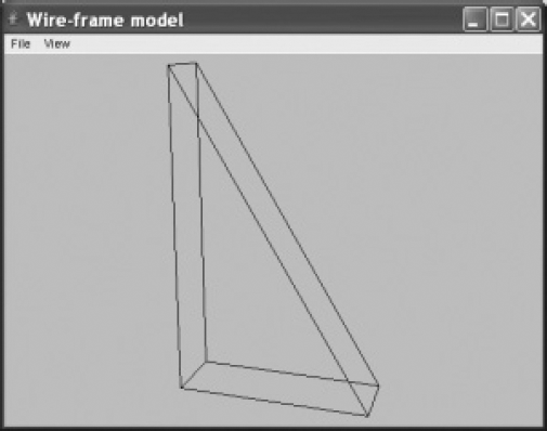
It is now time to see the program Wireframe.java in action. For example, let us use the object with vertices 1, 2, . . ., 6, shown in Figure 5.12.

With dimensions 1, 3 and 5 for the thickness, the width and the height, respectively, the following data file specifies this object:
1   1 0 0
2   1 3 0
3   0 3 0
4   0 0 0
5   1 0 5
6   0 0 5
Faces:
1 2 5.
3 4 6.
2 3 6 5.
1 5 6 4.
1 4 3 2.
When running program Wireframe.java and opening the above input file, a window as shown in Figure 5.13 appears.

By moving the point of view, using the Viewpoint to Right command from the View menu or its shortcut Ctrl+Arrow right a number of times, we obtain a different view of the same object, as shown in Figure 5.14.
Note that the program chooses a default viewing distance which is quite reasonable. If desired we can increase or decrease this distance using two commands from the View menu.
EXERCISES
5.1 Modify program CubePers.java of Section 5.4 in such a way that, with the given viewpoint, only the visible edges are drawn as solid black lines; draw the other, invisible lines in a different color, or, as usually in mechanical engineering, as dashed lines (see Exercise 1.5).
5.2 Use a fillPolygon method to display only the top, right and front faces of Figure 5.10 as filled polygons of different colors.
5.3 To prepare for Exercise 5.5, extend program CubePers.java of Section 5.4 so that two cubes beside each other are generated.
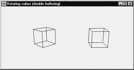
5.4 Use the class Rota3D of Section 3.9 to apply animation with double buffering to the cube of Section 5.4, using a rotation about some line, say, 0–6 (see Figure 5.11) through some small angle. If you are unfamiliar with animation in Java or with the Java class Image, required for double buffering, you will find the program Anim.java in Appendix F helpful.
5.5 As Exercise 5.4, but the rotation is to be applied to the two cubes of Exercise 5.3. Use different axes of rotation and increase the rotation angles for the two cubes by different amounts, so that the cubes seem to rotate independently of each other, with different speeds. Figure 5.15 shows a snapshot of the two cubes, each rotating about one of its vertical edges.