
Chapter 5. Iteration 1: Creating the Pattern
So far, the Oslec Software team has started to model some of the architecturally significant aspects of the solution, giving thought to the deployment, logical, and data aspects. While working on the architecture, they have begun to use patterns from outside sources (vendor and community) and have identified some patterns that are unique to their organization.
In this chapter we will follow the Oslec team as they continue to refine the work that has been completed so far. More specifically, they will give further thought to the design of the LogoAuction application and identify any shortcomings in the requirements and the architectural work done so far. In addition, they will pursue the implementation of the use cases, iteratively building the solution.
They will also continue their PBE work, as summarized in Figure 5.1.
Figure 5.1. Roadmap for this iteration where we focus on creating the pattern

The first step will be to design the Subsystem Façade pattern, focusing first on understanding the different pieces of the pattern; then they will analyze an exemplar and finish with the pattern implementation design.
With the design in hand the team can then start working on the specification as well as building the pattern implementation.
These steps will be shown sequentially; however, they are usually done in an iterative manner with some back-and-forth.
Launching the Iteration
Michael explains to the team that this iteration has two main goals. The first goal is to flesh out more solution details. In particular, Duncan’s team will focus on the Items Management subsystem, through the implementation of the main flow of the Put Item Up for Auction use case. This subsystem has been chosen because it is independent from, yet still representative of, the other subsystems. It provides a good way to validate the planned architecture without introducing unnecessary complexity. In addition, the work done by this team will serve as the basis for the exemplar for the Subsystem Façade pattern.
The second objective of the iteration is to build the Subsystem Façade pattern implementation. Alex and Jordan will lead the effort to design the pattern and will take advantage of the work done by Duncan’s team to validate the pattern and its variability points. Duncan is Oslec’s Java EE expert, so he will also provide assistance to Alex and Jordan in their efforts. In this collaboration Duncan is the Pattern Author/SME, Alex is the Pattern Specification Author, and Jordan is the Pattern Implementation Author.1
As mentioned earlier, Duncan and Alex have already been collaborating on the initial work on the pattern description and will continue to do so with the pattern specification. As they get into more detailed design, that collaboration effort will continue, and Jordan will join the discussions.
Designing the Subsystem Façade Pattern
Now that it has been deemed worthwhile to invest in the Subsystem Façade pattern, Alex and Jordan need to work on the design of the pattern.
Understanding the Essence of the Subsystem Façade Pattern
Before getting into the creation and analysis of the exemplar, Alex and Jordan want to ensure that they understand the essence of the pattern. To do so, they review the description of the Subsystem Façade pattern that was created in the previous iteration.
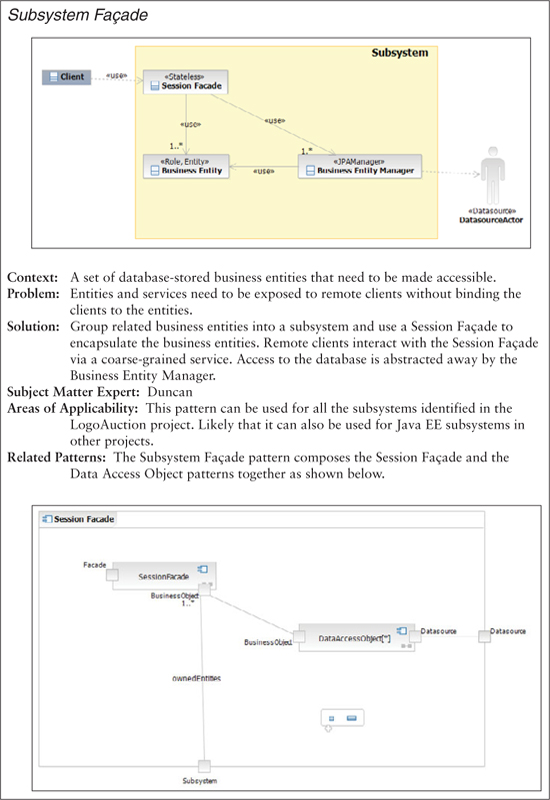
The pattern description indicates that the Subsystem Façade pattern results from the composition of the Session Façade and Data Access Object (DAO) patterns.2 Alex reviews the specifications of these existing patterns to ensure that he understands them. Figures 5.2 and 5.3 provide summaries of the patterns.
Figure 5.2. Overview of Session Façade pattern

Figure 5.3. Overview of Data Access Object (DAO) pattern
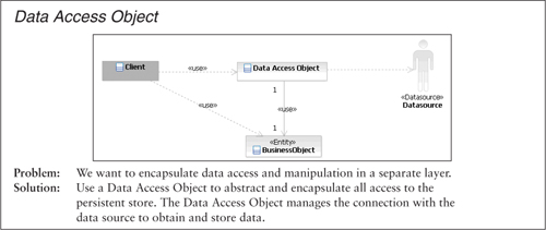
Alex determines that the way to connect these two patterns seems to be the BusinessObject class. The Session Façade can be used as is; however, the DAO pattern needs to be adapted to Java EE 5. Java EE 5 provides a new persistence framework called the Java Persistence API (JPA). One of the features provided by JPA is the JPA manager, which provides the same services as the DAO class in the DAO pattern. So while specifying the Subsystem Façade pattern, Alex replaces the DAO class with a JPA manager. He also notes that the goal of the Subsystem Façade pattern is to shield the content of a subsystem, so the Business Objects role will be fulfilled by the entities in the subsystem.
Alex updates the existing pattern description, which is shown in Figure 5.4. The effort has allowed him to gain a better understanding of the pattern and produce an artifact that can be used to solicit feedback from others.
Figure 5.4. Subsystem Façade pattern description
The team will use the pattern description in creating the related pattern specification and implementation. Following the Pattern Specification guideline (Chapter 13), the team decides to use a template with the following fields: Pattern Name, Context, Problem, Forces, Solution, Example, and Related Patterns.
Services: Dealing with an Overloaded Term
In working with the Façade3 pattern, we look to expose a set of services, hiding the underlying implementation. The Pattern User needs to worry only about the interface that is exposed by the façade, not the underpinnings. If we consider SOA-based solutions, we find a similar approach in use—we define a set of interfaces for a service, which becomes the contract that enforces the relationship between the service and a service consumer. However, in this case, when we use the term service, we usually mean something more specific than when discussing the Façade pattern (which is more general in its applicability).
In the case of Oslec, they are initially looking at using a more generic implementation of the Façade pattern. However, they could easily extend their solution later for SOA-based solutions. For example, if we look at the SOA Reference Architecture from IBM, shown in Figure 5.54 on page 76, we can see that the service components layer contains one or more components that provide implementations that get exposed as SOA services in the services layer. In this case it is likely that they will end up being web services. With the Subsystem Façade pattern, however, the Oslec team is focused on creating elements that live in the service components layer. They can later extend the pattern to support the services layer as well. Doing so would allow them to support an SOA initiative and provide a set of services for others to consume.
Figure 5.5. IBM SOA Reference Architecture
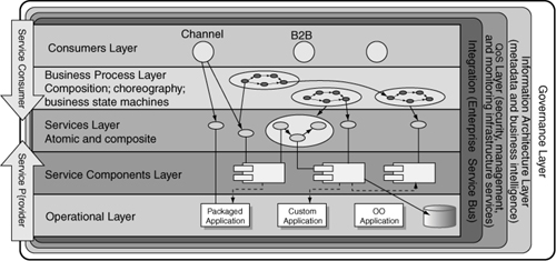
Copyright IBM developerWorks, www.ibm.com/developerworks. Reused with permission.
The Subsystem Façade Exemplar
With the pattern description for the Subsystem Façade pattern completed, the project team now needs to come up with a design for the pattern. The next step for Alex and Jordan is to acquire an exemplar.
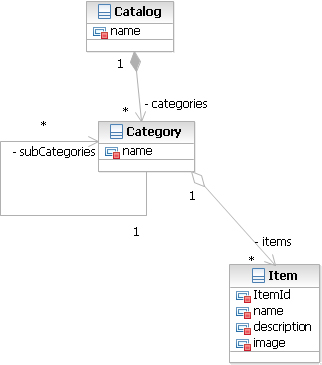
Duncan’s team is currently working on the Put Item Up for Auction use case, which requires the Items Management subsystem. Alex and Jordan plan to use this subsystem as the basis for the Subsystem Façade exemplar. Figure 5.6 shows that this subsystem contains three entities: Catalog, Category, and Item.
Figure 5.6. The elements associated with the Items Management subsystem

The team likes this approach, as the subsystem needs to be built anyway, they are supporting a key use case, and Duncan—the resident Java EE expert—is helping them build the solution. Alex, Jordan, and Duncan recognize that some variations will exist in the other subsystems that do not show up in Items Management. Once the subsystem is built, the three of them will review the solution, looking for areas where they need to augment and embellish it, creating an exemplar that suits the needs of all of the subsystems.
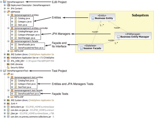
Figure 5.7 shows an overview of the structure of the resulting exemplar. There are many elements in the exemplar—projects, configuration files, XML files, Java files, test cases, referenced JAR files, packaging elements, and others. For a simple subsystem and pattern, they actually end up with many moving parts; if they were to replicate this work many times manually across a number of subsystems, there are ample opportunities for introducing errors.
Figure 5.7. Structure of the exemplar project
Analyzing the Exemplar
In this section we focus on following the Exemplar Analysis pattern (Chapter 12). The focus is to “identify the key entities involved in the pattern, specify the points of variability, define the information that the Pattern User provides, recognize the rules we can use to derive any additional information needed by the pattern, and identify the aspects of the pattern that stay the same across applications of the pattern.”5
Looking at the project structure, shown in Figure 5.7, Alex, Jordan, and Duncan identify the following roles:
• EJB project: defines the subsystem that will be encapsulated by the façade. It also contains libraries and JPA-related files such as orm.xml and persistence.xml.
• Entities: the business entities that are exposed by the façade. The exemplar contains three entities: Catalog, Category, and Item. Each entity has a JPA manager to abstract CRUD operations: CatalogManager, CategoryManager, and ItemManager.
• Façade: There is only one façade per subsystem, and its name can be derived from the name of the EJB project. A pair of elements, including a class and an interface, represents the façade.
• Test project: This project contains the tests that will be run against the EJB project elements. It also contains libraries and JPA configuration files to support the execution of JUnit tests outside the Java EE container. The name of the Test project can be derived from the name of the EJB project.
• Tests: These are the JUnit tests used to test the subsystem. There is one test for the façade and one test for each of the entity managers. Entities are usually simple enough that they don’t require a unit test of their own.
Using these roles, Alex and Jordan can start to define the input model. They need a subsystem parameter that helps them define the name of the EJB and Test projects as well as the name of the façade and its associated tests. That parameter will have a child parameter that will specify the entities and the managers that the façade will expose. With this relationship a subsystem can have many entities. Figure 5.8 shows the parameters and attributes that have been identified so far. A goal is to keep the input model as simple as possible. They look for opportunities to reuse information either as is or via calculations.
Figure 5.8. Current list of parameters

With this simple list of parameters and support from RSA, they determine the following:
• The Tests role does not require any additional information. Creating the initial testing infrastructure for the Pattern User will be seamless and encapsulated by the pattern.
• Infrastructure artifacts, such as Eclipse project elements and JAR files, are supported by RSA. It is unlikely that they will require any information from the Pattern User beyond what is provided for the subsystem entities.
• JPA persistence framework configuration files will use details directly related to the entities and the entity test cases. No additional parameters are required.
A More Detailed Look at the Exemplar
To dig deeper into the design Alex and Jordan need to start analyzing the internals of the exemplar artifacts. The focus of the effort is on identifying additional parameters. They want to ensure that they are finding all of the variations within the files. For example, even though each of the entity files is similar, there might be variations that are not present in all entities. As they work through the design, they will validate their findings with Duncan.
They start with the JPA entities as they are simple Java files. First they review the Item.java file, shown in Figure 5.9, and identify higher-order elements and relationships.
Figure 5.9. Beginning of the Item.java file with callouts for major sections

They identify six parts in the Item.java file: Package, Imports, Queries, Class Body, Attributes, and Operations. They examine each section to look for points of variability, those things that change as the pattern is applied. Here are their findings for each part:
• Package. They notice that the package name is similar to the project name except for two differences. The first difference is that the package name is shown entirely in lowercase letters. The second difference is that the package name is longer than the project name as it has .entities appended. Both of these differences from the project name are simple and can be calculated.
• Imports. Some of these imports are going to be easy to figure out based on the standard relationships between the entities in the solution. They are relatively static, requiring only the project name. Things get more interesting as they start to think about the entity’s attributes, since the Pattern User can specify a range of attribute types. Depending on the types that are specified, they may need to add more import statements. Based on this discovery, Duncan confirms that an attribute parameter is needed to provide the name and type of the attribute.
• Queries. The Queries section is new to Alex and Jordan, so they turn to Duncan for advice. Duncan explains that queries are based on JPA’s Java Persistence Query Language (JPQL). The purpose of JPQL is to allow the use of queries to retrieve entities from the data store without caring about the underlying implementation. Duncan explains that there are usually two kinds of queries. The first is linked to the entity’s attributes, such as getItemByName, and is used to retrieve entities using the attribute as a filter. The second query type is based on the entity, such as getAllItems and getAllItemsOrdered. This type of query is used to retrieve all the entities, ordered or unordered. Since they already have the attribute names, they are able to calculate the query names; there’s no need for a new parameter.
• Class Body. The class name needs to match the name of the entity. This is information they are already looking to capture, so no additional parameters are needed.
• Attributes. They recognize that there are two kinds of attributes. The first kind are the standard class attributes and will be tackled by the attribute parameter defined earlier. However, one of the attributes is special in the sense that it identifies the attribute/column used as an ID for persistence. This attribute is identified by the @Id annotation and will require a specific parameter identifying its name and type.
The second kind of attribute is based on associations. An association has a name and a type, but it also has an indicator for multiplicity (@ManyToOne), as well as an indicator of a mapped column (CATEGORY_ID). So they need to add an association parameter with four attributes: name, type, multiplicity, and target column.
• Operations. Operations are straightforward as they are dealing with entities. Entity operations consist of only get and set operations to retrieve and set the entity attributes.
The resulting set of parameters and attributes is summarized in Figure 5.10. The changes that have been made to the input model include
• attribute, described by its name (attrName) and type (attrType)
• id, described by its name (idName) and type (idType)
• association, described by its name (assoName), type (assoType), multiplicity (multiplicity), and table column name (targetField)
Figure 5.10. Summary of the identified parameters and their attributes

Using the same approach, Alex and Jordan look at the JPA managers in the controllers package. They do not find any new parameters, as the managers mainly provide the CRUD operations for the entity. The exemplar contains three controllers, and after checking with Duncan, they decide to use the ItemManager as a base for the manager template as it is the most representative.
The façade in the exemplar is pretty basic and provides operations to access an entity using its id and to retrieve all the entities. When looking at the façade, they note that there is a pairing between a class and an interface. The relationship between the two is quite direct; Jordan notes that he will need the pattern implementation to generate them as a pair.
Duncan points out that a variation they need to add to the exemplar is the use of the Embedded Value pattern. The pattern currently is used only in the Auction Management subsystem. Figure 5.11 shows an example of the application of the pattern to the Money class. A key aspect of the pattern is that the Money class does not have its own table in the database. Instead, the values associated with an instance of Money are stored along with the object that uses that instance of Money, in this case the Payment class.
Figure 5.11. Example of the application of the Money pattern

The Money class has two attributes: amount and currency. Duncan provides Alex and Jordan with Listing 5.1, which includes two examples of using the Money pattern. Alex and Jordan also notice that the Money class, among other utilities, is stored in the AuctionUtility Java project. Duncan explains that the first example in the Payment.java file is the simple case. In this case the column names are the same as the Money class’s attributes. The second case, in the Bid.java file, shows how to declare new column names. Duncan also indicates that no queries are created for embedded attributes.
Listing 5.1. Examples of Using the Money Pattern6
============= Payment.java ===========================
@Embedded
private Money amount;
============= Bid.java ================================
@Embedded
@AttributeOverrides( {
@AttributeOverride(name="amount", column=@Column(name="CURRENTBID")),
@AttributeOverride(name="currency", column=@Column(name="CURRBIDCURRENCY"))
})
private Money currentBid;
Based on their analysis of Listing 5.1, Alex and Jordan recognize that they need to update their input model. First they will need a new parameter to identify embedded value attributes. The new parameter should capture the embedded value’s name and type as well as an optional child parameter in cases where the column names are overridden. This parameter for overridden names will need two attributes, one for the name of the overridden attribute and one for the name of the corresponding column. Another change they need to make is to support project dependencies, as seen with the import of the Money class, which is stored in the utility project. Jordan creates a dependency parameter under subsystem, allowing him to dynamically add dependencies.
To ensure that they did not overlook anything, Alex and Jordan consult the domain model to validate that all its elements can be mapped to the points of variability identified as well as the other way around—all the variability points can be derived from the model. In doing so, they notice that there is no identification of the subsystems in the domain model, so they consult with Gwen to determine how to address this issue. After learning the role of the subsystems, Gwen finds that they directly map to the responsibility areas she has been identifying on the main domain model diagram. To make the domain model easier to transform, she agrees to group the entities by subsystem in different packages.
Looking at the domain model again, they see that there is no mechanism on the current list of parameters to address inheritance or abstract classes such as the Role class. Adding an abstract attribute to the entity easily solves supporting abstract classes. Inheritance turns out to be more complex, so they ask Duncan for assistance. Duncan provides Listing 5.2 as an example of inheritance between User (the parent) and Administrator (the child).
Listing 5.2. Example of Inheritance Use
============= User.java ====================
@Entity
@Inheritance(strategy=JOINED)
public class User implements Serializable {
@Id
@Column(name="USER_ID")
private long userId;
private String name;
============= Administrator.java ==============
@Entity
public class Administrator extends User implements Serializable {
private boolean admin;
When they review the example, Alex and Jordan see that the parent, User, has an @Inheritance(strategy=JOINED) annotation and that the child, Administrator, extends the parent class but does not have an @ID annotation. Duncan explains that only the JOINED inheritance strategy is used at Oslec, so there is no need to parameterize it. To support these discoveries they decide to add to the input model. They will need to add two attributes to the entity parameter—hasChild, to identify an entity that has children, and parent, to identify that a class is part of an inheritance tree—and provide the name of the entity it needs to extend. The bidirectional nature of the parameters simplifies capturing and processing the relationship in XML.
Figure 5.12 shows the list of parameters at the end of exemplar analysis. The changes that have been made to the input model include the following:
• dependency, with one attribute for the name of the project the subsystem depends on (depName).
• Three attributes for the entity node to indicate its abstractness (isAbstract) and inheritance (hasChild and parent).
• embeddedAttribute captures the name (embAttrName) and type (embAttrType) of the embedded attribute. It also contains an optional node (attrOverride) to specify cases where the name of an attribute has been overridden. The attrOverride node captures the name of the corresponding column in the database (attrLocalName), as well as the name (attrName) and the type (attrType) of the overridden attribute.
Figure 5.12. Identified parameters and their attributes

The design work done so far has more or less been common to the pattern implementation and specification. It is now time for Jordan to look at design decisions specific to the pattern implementation.
Design of the Pattern Implementation
Jordan’s first step in designing the pattern implementation is to determine the type that should be built. Two factors influence the decision. The first is that Oslec used UML and models to design its applications. The second is that the exemplar contains many text-based artifacts. With these two considerations in mind, Jordan decides that he will follow the Model-to-Text Pattern Implementation pattern (Chapter 13). The pattern implementation will be applied to the domain model and will generate a set of text-based artifacts.
To implement the pattern Jordan decides to combine two technologies provided by Rational Software Architect. He will use JET to create the text-based artifacts, including Java code and XML-based configuration files. To simplify the user experience in creating the input model, Jordan will leverage RSA’s model-mapping capabilities. This will allow the Pattern User to specify a UML model, known as the user model, which will then be translated by the pattern into the input model that is needed for the JET-based portion of the pattern implementation. He also plans to use the Integrated Patterns and DSLs pattern (Chapter 15) to help ensure that the user model is built out as simply—and correctly—as possible.
Jordan also wants to ensure that he is simplifying the set of patterns that he is providing to the Pattern Users. He selects the Compound Pattern pattern (Chapter 12) to help him meet this goal. So far, the Subsystem Façade pattern implementation includes the Session Façade, DAO, Role, Money, Embedded Value, and Class Table Inheritance patterns, as shown in Figure 5.13.
Figure 5.13. Patterns included in the Subsystem Façade pattern implementation

Because the LogoAuction project is using an iterative approach, there is a need to ensure that the pattern implementation will provide support for reapplication so that the pattern implementation can be reapplied on components while preserving handwritten code that’s been added to designated areas. Code that exists outside the designated areas is owned by the pattern implementation and will be overwritten each time the pattern is applied. Jordan leverages the Team Pattern Implementation Use guideline (Chapter 12) to help him design this aspect and will also use it in enabling the Pattern Users.
Creating the Subsystem Façade Pattern Specification
While Jordan is working on the design of the pattern implementation, Alex continues working on the pattern specification.
At this point in its PBE adoption, Oslec has not yet selected a pattern specification template. Alex reviews some of the available templates and decides to create a template reusing the sections he found meaningful and useful from the available templates. Then, using the pattern design and with some help from Duncan on the examples, he writes the pattern specification.
When he has a stable enough pattern specification, Alex organizes a peer review of it with Jordan, Duncan, Sandy, and Craig. The final version is provided in Appendix E.
Building the Subsystem Façade Pattern Implementation
With the initial design in hand and his notes resulting from the exemplar analysis, Jordan can start building the pattern implementation, beginning with the JET component.
Building the JET Component
Test-Driven Development
Jordan has experienced the benefits of using test-driven development in previous projects and would like to apply it in this effort. He decides to use the ItemsManagement project as his reference for the test case. This will allow him to compare the pattern output to the exemplar project. However, to avoid overwriting the exemplar within his workspace, he names the subsystem Items2.
To identify the content of the input model for the test case, he returns to the domain model and focuses on the business entities within the Items Management subsystem. These entities and their relationships are shown in Figure 5.14.
Figure 5.14. ItemsManagement entities
Using the diagram shown in Figure 5.14, Jordan creates the test input model. He uses XML to specify the test input model, as that is the default language that JET accepts. The first version of the test input model is shown in Listing 5.3. It’s a simple test that creates the subsystem.
Listing 5.3. Initial Test Input Model
<?xml version="1.0" encoding="UTF-8"?>
<root xmlns:xsi="http://www.w3.org/2001/XMLSchema-instance"
xsi:noNamespaceSchemaLocation="schema.xsd">
<subsystem subsName="Items2" />
</root>
As he proceeds through the creation of the JET component, he enhances the test case. He alternates test case enhancement efforts with JET component enhancements, ensuring that the component passes the test before adding functionality. Listing 5.4 shows the final test input model.
Listing 5.4. Final Test Input Model
<?xml version="1.0" encoding="UTF-8"?>
<root xmlns:xsi="http://www.w3.org/2001/XMLSchema-instance"
xsi:noNamespaceSchemaLocation="schema.xsd">
<subsystem subsName="Items2">
<entity entityName="Item">
<attribute attrName="name" attrType="String" />
<attribute attrName="description" attrType="String">
</attribute>
<attribute attrName="image" attrType="byte[]" />
<id idName="Item_Id" idType="long"></id>
<association assoName="categoryId"
assoType="items2management.entities.Category"
multiplicity="manyToOne"
targetField="CATEGORY_ID" />
</entity>
<entity entityName="Category">
<attribute attrName="name" attrType="String" />
<id idName="category_Id" idType="long" />
<association assoName="catalogId"
assoType="items2management.entities.Catalog"
multiplicity="manyToOne"
targetField="CATALOG_ID">
</association>
<association assoName="parentcatId"
assoType="items2management.entities.Category"
multiplicity="manyToOne"
targetField="PARENTCAT_ID">
</association>
<association assoName="subcategories"
assoType="java.util.Set
<items2management.entities.Category>"
multiplicity="oneToMany"
targetField="parentcatId">
</association>
<association assoName="items"
assoType="java.util.Set
<items2management.entities.Item>"
multiplicity="oneToMany"
targetField="categoryId">
</association>
</entity>
<entity entityName="Catalog">
<attribute attrName="name" attrType="String" />
<id idName="catalog_Id" idType="long" />
<association assoName="categories"
assoType="java.util.Set
<items2management.entities.Category>"
multiplicity="oneToMany"
targetField="catalogId">
</association>
</entity>
</subsystem>
</root>
Getting Started with the JET Project
To create the JET component, Jordan uses the Exemplar Authoring capability in RSA. To get started, he creates an Exemplar Authoring7 project and links it to the ItemsManagement exemplar project. Once the project is set up, Jordan specifies the parameters (called types in JET) and attributes that were identified during the exemplar analysis efforts in the design phase.
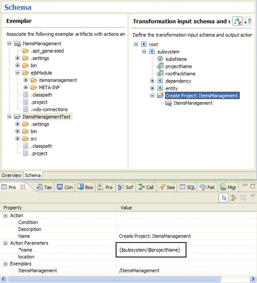
Figure 5.15 shows the main view of Exemplar Authoring. The left pane contains the two projects identified as the exemplar, and the right pane contains the initial list of types and attributes. As the team works through Exemplar Authoring, they will add more details to the types and attributes, defining attributes that can be calculated or derived from other attributes as well as defining actions that the pattern implementation needs to take to create files.
Figure 5.15. Exemplar Authoring main view

Creating Elements
Jordan recognizes that he has to create an EJB project for each subsystem. To do so, he drags the ItemsManagement project from the Exemplar pane and drops it on the subsystem element in the right-hand pane. A Create action for the EJB project is added to the right-hand pane, indicating that for each subsystem type specified by the Pattern User, an EJB project will be created. The name of the EJB project is of the form <Subsystem_Name>Management, which Jordan parameterizes to ensure that the correct name is assigned. This is done in the Exemplar Authoring tool by replacing the name with a model reference in the properties of the Create action. Note that such customization of the pattern implementation to support dynamic data access and calculations is done using XPath, since the input model is an XML file. When the input model provided by the user is made available to the pattern implementation, it is presented as a Document Object Model (DOM), essentially a tree structure.
There are two options for customizing this attribute:
- Replace
ItemsManagementin the name property field with{$subsystem/@subsName}Management, appending the stringManagementto thesubsNameattribute. - Create a new derived attribute
projectNameset to{$subsystem/@subsName}Managementand then replaceItemsManagementin the name property field with a reference to this variable ({$subsystem/@projectName}).
Jordan chooses the second option,8 using a derived variable, as there is more than one place where he will need this value. Figure 5.16 shows the updated Exemplar Authoring view as well as an example of the parameterization of the project name.
Figure 5.16. Updated Exemplar Authoring view
Next, Jordan needs to identify all the elements inside the project that are created only once per subsystem and drag them under the subsystem type. Some obvious ones are the project metadata files (.project, .classpath, .settings, etc.) and the ejbModule source directory. These elements have names that are not dependent on the subsystem; regardless of the subsystem name, the project configuration file will be called .project and the source directory ejbModule. What is important to understand here is that we are looking only at the names of the elements, not the content. The content of some of the files will change based on the projectName attribute.
There is no variability associated with the file names, so Jordan just has to drag them under the Create Project: ItemsManagement node and does not need to make any modifications. Another set of elements that falls into that category is the META-INF directory and its content (orm.xml and persistence.xml); he treats them in the same fashion.
So far the changes have been pretty simple. Now Jordan explores the content of the source directory, and things start to get a little more involved. As shown in Figure 5.17, the source directory contains three packages: itemsmanagement.entities, itemsmanagement.facade, and itemsmanagement.entities.controller. In Eclipse, packages are physically represented by directories, so the pattern implementation must create these four directories (itemsmanagement is also a directory). From the content of these different packages, only the façade and its interface need to be added to the list as they are created once per subsystem. Jordan drags all the identified directories and files under the subsystem type and parameterizes them the same way he did for the project.
Figure 5.17. ItemsManagement source directory

Now that he is done with the subsystem-dependent elements, Jordan decides to tackle the entity-dependent elements before starting to parameterize the different files.
Entity-dependent elements are those that are typically associated with an entity. Within the exemplar project there are three entities to choose from: Catalog, Category, and Item. There is no need to add all of them to the output actions as they represent variations of the same type of artifact. Jordan needs to drag only one of the entities and the corresponding manager to the right-hand pane under the entity type and then parameterize it. Jordan selects Item as it is most representative of the type, the one that is the most complete and displays the most variability. Jordan adds Create File actions for the Item.java and ItemManager.java classes under the entity element. These actions will create the two files for each entity. Figure 5.18 shows the updated content in the Exemplar Authoring view.
Figure 5.18. Exemplar Authoring view with all the subsystem-dependent elements

Next, Jordan needs to parameterize the JET templates. To get the process started, he generates an initial version of the templates from the Exemplar Authoring view.
Updating the Elements Templates
At this point Jordan turns his focus to the JET templates and the content within. He starts the process by generating the JET templates.
Note
We will not detail all of the template editing and parameterization that Jordan performs as the work gets repetitive—and there are quite a few templates. Instead, we will look at a few examples of some of the possible and likely scenarios when working with JET files.
Jordan starts with the project.jet file that generates the .project file of the Eclipse project. This is good place to start, as the contents of this file are relatively static; the only thing that will need to be modified is the name of the project. In JET this is done using the <c:get> tag to reference the projectName attribute from the subsystem type. Recall how Jordan customized the derived attributes associated with the input model; he used XPath for calculations and data access via the DOM-based input model. Listing 5.5 shows the beginning of the project.jet file with the use of the <c:get> tag that Jordan has used to access the projectName attribute of the subsystem entity.
Listing 5.5. Beginning of project.jet File9
<?xml version="1.0" encoding="UTF-8"?>
<projectDescription>
<name><c:get select="$subsystem/@projectName" /></name>
<comment></comment>
<projects>
</projects>
Another interesting file to examine is the Item.java.jet template, shown in Listing 5.6.
Listing 5.6. Beginning of Item.java.jet File
package itemsmanagement.entities;
import itemsmanagement.entities.Category;
import javax.persistence.JoinColumn;
import javax.persistence.ManyToOne;
import java.io.Serializable;
import javax.persistence.Entity;
import javax.persistence.Id;
import javax.persistence.NamedQuery;
import javax.persistence.NamedQueries;
import javax.persistence.Column;
@Entity
@NamedQueries( {
@NamedQuery(name = "getItemByName",
query = "SELECT i FROM Item i WHERE i.name = :name"),
@NamedQuery(name = "getItemByDescription",
query = "SELECT i FROM Item i
WHERE i.description = :description"),
@NamedQuery(name = "getItemByImage",
query = "SELECT i FROM Item i WHERE i.image = :image"),
@NamedQuery(name = "getAllItems",
query = "SELECT i FROM Item i"),
@NamedQuery(name = "getAllItemsOrdered",
query = "SELECT i FROM Item i ORDER BY i.Item_Id")
})
public class Item implements Serializable {
@Id
@Column(name = "ITEM_ID")
private long itemid;
private String name;
private String description;
private byte[] image;
private static final long serialVersionUID = 1L;
@ManyToOne
@JoinColumn(name = "CATEGORY_ID")
private Category categoryId;
public Item() {
super();
}
public long getItemid() {
return this.itemid;
}
public void setItemid(long itemid) {
this.itemid = itemid;
}
Jordan looked at the file during the exemplar analysis activity; now he uses the parameters he identified to add variability to the template. He notices that there is an attribute declaration for each attribute, so he will need to use the <c:iterate> tag to iterate through an input model type (in our case the entity attributes). Listing 5.7 shows the use of <c:iterate> for the attributes declaration. In this way Jordan dynamically builds the attributes owned by the entity.
Listing 5.7. Example of the <c:iterate> Tag for Attributes in Item.java.jet
<c:iterate select="$entity/attribute" var="attribute">
private <java:import><c:get select="$attribute/@attrType"/>
</java:import> <c:get select="$attribute/@attrName" />;
</c:iterate>
There is also one query per attribute, so Jordan adds an iterate tag to add the attribute name and type to the entity file, as shown in Listing 5.8.
Listing 5.8. Example of the <c:iterate> Tag for Queries in Item.java.jet
<c:iterate select="$entity/attribute" var="attribute">
@NamedQuery(name="get<c:get select="$entity/@entityName" />By
<c:get select="uppercaseFirst($attribute/@attrName)" />",
query = "SELECT <c:get select="lower-case(substring($entity/@entityName,1,1))" />
FROM <c:get select="$entity/@entityName" />
<c:get select="lower-case(substring($entity/@entityName,1,1))" />
WHERE <c:get select="lower-case(substring($entity/@entityName,1,1))" />.
<c:get select="$attribute/@attrName" /> = :
<c:get select="$attribute/@attrName" />"),
</c:iterate>
Next, Jordan examines the relationships within this entity. By looking at the many-to-one relationship within Item.java, shown in Listing 5.9, Jordan realizes that he must update the input model with a new association attribute to store the name of the join column. He also suspects that there are other multiplicities, so he starts looking at the other entities that were provided in the exemplar. In the Category entity he finds an example of a one-to-many relationship, reproduced in Listing 5.10.
Listing 5.9. Example of Many-to-One Association
@ManyToOne
@JoinColumn(name="CATEGORY_ID")
private Category categoryId;
Listing 5.10. Example of One-to-Many Association
@OneToMany(mappedBy="categoryId",fetch=FetchType.EAGER)
private Set<Item> items;
Jordan notices that the code for a one-to-many relationship has the same number of variables as the code for the many-to-one relationship. The only difference is that the join column is replaced with a mapping attribute. Since the meaning of the attribute is similar between the two, Jordan decides to reuse the attribute created for specifying the join column, keeping things simple.
In a further review of the entities, Jordan does not find any additional examples of different types of relationships. Before moving ahead, he asks Duncan to confirm that all relationship types have been identified. Duncan tells him that a third type of association is used in the company: a many-to-many relationship. A many-to-many relationship is created by annotating both classes in the relationship. One of them defines the join table using an @JoinTable annotation. The other class makes a reference to the join table attribute much like a one-to-many relationship (except that @OneToMany is replaced with @ManyToMany). Duncan provides the example shown in Listing 5.11, further explaining that the only fetching option they use is EAGER.
Listing 5.11. Example of Many-to-Many Association
@JoinTable(name="PHONE_X_USER",
joinColumns=@JoinColumn(name="PHONE_ID"),
inverseJoinColumns=@JoinColumn(name="USER_ID"))
@ManyToMany(fetch=FetchType.EAGER)
private Set<User> users;
Jordan notices that there are three variability elements, as shown in Listing 5.11: the name of the join table, the name of the join column, and the name of the inverse join column. The only information not yet available in the association type is the join table and the inverse join column names. So he adds them to the input model.
Listing 5.12 shows the parameterization of the associations inside the entity Java class using the following JET tags:
• <c:iterate> to iterate through the associations
• <c:choose> and <c:when> to provide a behavior depending on a test (here the value of the multiplicity)
• <java:import>, allowing the addition of an import statement for the type of the entity
Listing 5.12. Parameterization of the Association
<c:iterate select="$entity/association" var="association">
<c:choose select="$association/@multiplicity">
<c:when test="'oneToMany'">
@<java:import>javax.persistence.OneToMany</java:import>
(mappedBy="<c:get select="$association/@targetField" />",
fetch=<java:import>javax.persistence.FetchType</java:import>.EAGER)
private <java:import><c:get select="$association/@assoType"/>
</java:import> <c:get select="$association/@assoName" />;
</c:when>
<c:when test="'manyToOne'">
@<java:import>javax.persistence.ManyToOne</java:import>
@<java:import>javax.persistence.JoinColumn</java:import>
(name="<c:get select="$association/@targetField" />")
private <java:import><c:get select="$association/@assoType"/>
</java:import> <c:get select="$association/@assoName" />;
</c:when>
<c:when test="'manyToManyRef'">
@<java:import>javax.persistence.ManyToMany</java:import>
(mappedBy="<c:get select="$association/@inverseField" />")
private <java:import><c:get select="$association/@assoType"/>
</java:import> <c:get select="$association/@assoName" />;
</c:when>
<c:when test="'manyToMany'">
@<java:import>javax.persistence.ManyToMany</java:import>
@<java:import>javax.persistence.JoinTable</java:import>
(name=" <c:get select="$association/@joinTable" />",
joinColumns=@<java:import>javax.persistence.JoinColumn</java:import>
(name="<c:get select="$association/@targetField" />"),
inverseJoinColumns=@<java:import>javax.persistence.JoinColumn
</java:import>
(name="<c:get select="$association/@inverseField" />"))
private <c:get select="$association/@assoType" /> <c:get select="
$association/@assoName" />;
</c:when>
</c:choose>
</c:iterate>
One of the requirements outlined in Chapter 4 was the ability to reapply the pattern while preserving any modifications to the generated code. To support this requirement, Jordan leverages the Team Pattern Implementation Use guideline (Chapter 12). The idea is to provide a way for developers to modify the code within generated files without having the pattern overwrite or delete the modification upon reapplication of the pattern. Implementing such a solution with JET consists of defining user-preserved areas within the templates. The corresponding JET tag is <c:userRegion>. The <c:initialCode> tag specifies content to be written to the file the first time the pattern implementation is executed. Listing 5.13 provides an example of the use of these tags in the JET template of the façade (AuctionFacade.java.jet).
Listing 5.13. Use of the Preserved Area Tag in the Façade JET Template
<c:userRegion>
// BEGIN user-region operations
<c:initialCode>
/*
* Add your business methods between the BEGIN and END tags
*/
</c:initialCode>
// END user-region operations
</c:userRegion>
Jordan will go through the remaining files to add variability where it makes sense. The work will involve repeating the steps that we’ve discussed here, using JET tags to access and work with the data from the input model. In this way he will be able to inject dynamic elements into the static structure of the templates.
Unit-Testing the JET Implementation
As part of his development approach Jordan has been regularly testing with the test input model as described earlier. At this stage he will perform a test with the complete input model that was shown in Listing 5.4.
Jordan runs the JET pattern implementation and compares the results with the exemplar project. As this is a case study, they conveniently match on first testing! Figure 5.19 shows the structure of the generated project.
Figure 5.19. Items2Management-generated project

Jordan plans additional tests, including
• Changing one of the associations to be a many-to-many association (remember that there was no such association in the exemplar, which is why it was not identified during the design)
• Adding an embedded attribute to the Item entity to check that the JET component generates the appropriate code
JET Implementation for the Test Project
Now that the pattern seems to work fine for the EJB project, Jordan turns to the Test project. He repeats the steps described previously to parameterize the generation of the Test project. The input model stays essentially the same, aside from Create File actions to support the creation of the Test project and associated files. Figure 5.20 shows the resulting Exemplar Authoring view.
Figure 5.20. Resulting Exemplar Authoring view

Now that the implementation of the JET piece of the pattern implementation is developed and tested, Jordan can move on to developing the UML front end for the pattern. He will reuse an Eclipse Modeling Framework (EMF)10 model (input.ecore) corresponding to the JET input model as he works on the UML front end. The EMF model was automatically generated by the Exemplar Authoring tool and formally specifies the input model.
Implementing the UML Front End for the Pattern
In this section we follow Jordan as he creates the model-mapping component that will process UML and connect to the JET component within the pattern implementation. As discussed in the previous chapter, the input for the Subsystem Façade pattern implementation is the domain model. The domain model is defined using UML and is maintained by Gwen.
Building the DSL11
Reading the Integrated Patterns and DSLs PBE Pattern (Chapter 15), Jordan realizes that he should develop a DSL that Gwen can use to mark up the domain model and make the Subsystem Façade more consumable. Because they use UML, he chooses to use a UML Profile as the basis for the DSL.
The first thing Jordan does is to go back to the JET component of the pattern implementation to look at the input model and identify what elements can be directly derived from UML and what would need a specific stereotype to denote them. Figure 5.21 shows a summary of the JET input model types and attributes.
Figure 5.21. Input model parameters and attributes

When they analyze the input model and the domain model, Jordan and Gwen make the following decisions:
• Previously, Gwen had agreed to use packages to organize the subsystems in the domain model. However, not all of the packages in the domain model will be subsystems. So Jordan creates a «Subsystem» package stereotype that Gwen will use to identify the packages corresponding to subsystems.
• Dependencies can be derived from the UML dependencies between two subsystems, so no stereotype is needed.
• Not all classes inside a subsystem package are necessarily entities, so Jordan creates an «Entity» class stereotype to be applied to entity classes.
• Entity attributes and relationships can be derived from the UML attributes and relationships, so no additional markup is required.
• Embedded attributes, attributes of a related class that are persisted into the table of the containing class, will need to be denoted. To identify them, Jordan adds an «EmbeddedAttribute» property stereotype.
• The last stereotype that Jordan provides is «Id». The «Id» property stereotype is used to support the specification of a particular database table ID. The rule in the company is to name the ID of a column following the pattern <TABLE_NAME>_ID (i.e., the ADDRESS table leads to ADDRESS_ID). However, Jordan wants to allow the opportunity to enter a specific ID in case someone has to use a legacy database that does not adhere to the naming convention.
With these four basic stereotypes and the UML syntax, Jordan should be able to gather all the information he needs for the input model. Figure 5.22 summarizes the stereotypes Jordan creates as well as the relationships between them. The metaclasses are used to identify the type of UML elements to which the stereotype can be applied. Jordan does not want to overinvest in the profile and create specific icons because there are only a few users of the profile.
Figure 5.22. Subsystem Façade profile stereotypes

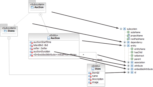
With the profile in hand, Jordan works with Gwen to test the pattern. The goal of the test is to ensure that the profile contains only those elements that are meaningful to her domain. They decide that the best way to validate the profile is to try to apply it to one of the subsystems. Jordan and Gwen choose the Auction subsystem as it contains the most variability. The result of this test is shown in Figure 5.23.
Figure 5.23. Auction subsystem entities with their stereotypes and dependencies

They are both pleased with the results of the test. Jordan can now move to the implementation of the UML front end of the pattern implementation while Gwen continues applying the profile to the rest of the domain model.
Test-Driven Development
Jordan realizes that he needs to put together his plans and test cases for this portion of the pattern implementation. One test case is already available: he can test the Auction subsystem that was used to test the new profile.
In addition to looking at the input models for the test cases, he knows that he wants to isolate the component under test as much as possible. To that end, he decides to leverage the Ecore model that was generated along with the JET component.
Implementing the Model-Mapping Component
Building the model-mapping component consists mainly of mapping UML elements (with or without a stereotype applied) to the corresponding elements defined in the Ecore model that represents the input model of the JET component. We will refer to the UML model as the user model because it is the model that the Pattern User will work with. This model may end up containing more information than is needed for the input model, that is, the model that is required for the JET component. Thus, a single user model may work with multiple pattern implementations and support the generation of a wide range of output artifacts. Also, it allows the team to focus on creating a user-friendly representation of the user model, without being overly constrained by the input model needed by the JET component.
The easiest way to perform this with RSA is by using the Model to Model Mapping feature. Jordan uses the UML Interface to a JET Transformation wizard to generate the needed infrastructure for the Model-Mapping project. This infrastructure contains the UML front end project itself, the model project providing a Java API to navigate the Ecore input model, as well as a feature packaging them with the JET component, making the packaging and deployment easier. The resulting projects are shown in Figure 5.24.
Figure 5.24. Pattern implementation projects

Note
When creating a model-mapping project, the project creation wizard expects to have an input and output model. We can assign one or more metamodels to each of these models. Things can get a little confusing when we connect this component with a JET component. The JET component also has an input model. Generally the input model for the model-mapping component should be considered the user model. The output model from the model-mapping component is the input model for the JET component.
In creating the Model-Mapping project he selects UML and the Subsystem Façade profile as the input model (our user model). He then selects the Eclipse Ecore model representing the input model of the JET transformation as the output model.
When building the model-mapping component with RSA, Jordan will create a series of maps that describe how an element from the input model is translated into one or more elements in the output model. To identify which maps he will need to create, Jordan performs a brief analysis of the elements in his profile and the schema associated with the JET component. In this analysis he identifies which UML elements map to which input model elements. Figure 5.25 shows a conceptual view of the high-level mapping between UML elements and the JET input model. Each of the arrows in the figure represents a mapping that needs to be implemented.
Figure 5.25. View of the conceptual mappings between UML elements and the input model
He starts by creating an initial map, called ModelToRoot, for extracting the packages with the «Subsystem» stereotype from the input model and feeding them into the subsystem nodes in the output model. Figure 5.26 shows the resulting map. The Submap mapping indicates that the mapping is delegated to another map; this is usually used to iterate through elements where there is a collection of elements. Identification of the packages with the «Subsystem» stereotype is done through a custom extractor12 retrieving only the relevant packages.
Figure 5.26. ModelToRoot map

The subsystem and dependency mappings are straightforward; Jordan just gathers the name of the subsystem and the name of its dependent subsystem.
The entity mapping is interesting, not because it is complex but because it is the hub from where the other maps will be derived and connected. Figure 5.27 shows the («Entity») ClassToEntity map with a set of submaps that allow Jordan to iterate through the different subnodes of the entity (association, attribute, embeddedAttribute, and id). The Move mapping is used to specify that the name of the entity is copied into the entityName attribute.
Figure 5.27. «Entity» ClassToEntity map

To create the mapping between UML associations and the associations in the entity element in the output model, Jordan needs to keep in mind the way that this information is modeled in UML. Figure 5.28 provides an overview of how elements are derived from an association. The UML association multiplicities (1–*) are used to define the multiplicity of the association attribute (oneToMany) in the output model. The name and type of the association are defined by the associated UML «Entity», and the targetField attribute is derived from the name of the «Entity» following Oslec Software naming conventions (categoryId).
Figure 5.28. Conceptual mapping of the UML association to the input model association parameter

Another interesting mapping is the one for the embeddedAttribute element. Figure 5.29 provides a conceptual view relating elements in the UML-based input model to elements in the output model. In this case the embedded attribute name and type are derived from the UML attribute with the «EmbeddedAttribute» stereotype. The attributes’ names and types are derived from the type class.
Figure 5.29. Conceptual mapping of the «EmbeddedAttribute» property to the input model embeddedAttribute parameter

Once all of the mappings have been specified, Jordan generates the code for the model-mapping component.
Unit-Testing the Model-Mapping Component
RSA provides an option to save the intermediate Ecore model generated by the model-mapping transformation. This is very useful in unit-testing the model-mapping component. Jordan uses this capability to unit-test the pattern implementation and ensure that it generates a proper Ecore model. To perform this test he uses the portion of the domain model related to the Items subsystem, as shown in Figure 5.30.
Figure 5.30. Items subsystem entities with their stereotypes

Jordan uses the Items subsystem; it will be easy for him to validate the generated Ecore model as it is the same as the one used in the JET testing. When they match, he can then move to the next level of testing.
Testing the Full Pattern Implementation
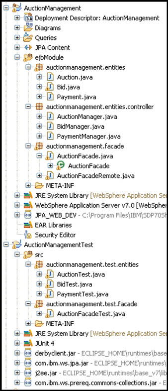
After finishing his tests of the model-mapping component, Jordan now turns to testing the full, connected implementation. He uses the Auction subsystem again to help in confirming that there are no errors. The output from running the full pattern implementation is shown in Figure 5.31. He asks Duncan to review the content to check that everything is fine.
Figure 5.31. Auction-subsystem-generated projects
As a follow-on step, Duncan, Jordan, and Gwen review the test input artifacts and results. Duncan confirms that the content generated by the pattern indeed aligns with expectations in terms of content, interpretation of user input, coverage of variability, and quality. Gwen reviews the domain model and is satisfied with both the model and the DSL. However, she also requests an enhancement to the profile; she’d like to be able to identify in the model the business services provided by the entities and have these services generated automatically as exposed operations into the subsystem façade. It is too late to add this feature to this release, but Jordan adds it to the backlog list of future enhancements to the pattern.
Summary
At this point Jordan and Alex have specified the Subsystem Façade pattern and built the corresponding pattern implementation. As mentioned earlier in this chapter, a pattern implementation usually automates more than one pattern, and the Subsystem Façade pattern also follows this rule, encapsulating a number of patterns (as shown previously in Figure 5.13).
Figure 5.32 summarizes the PBE roles, tasks, Patterns, and Guidelines that have been covered in this chapter.
Figure 5.32. Summary of the PBE elements covered in this chapter
