
Chapter 2. Examples of Pattern Implementations
In this chapter we look at examples of pattern implementations. When working with PBE, we work with both pattern specifications and pattern implementations. However, practitioners are usually more familiar with pattern specifications. So although pattern implementations are just one part of PBE, we focus on them, as not only are they a new concept; they are a critically important part of PBE. Being able to create an automated version of our patterns increases the impact we can have with our patterns and significantly affects our productivity, our ability to consistently apply patterns, and the quality of the resulting solutions.
We will familiarize ourselves with the different types of pattern implementations and their uses. The goal is to help make the different types of pattern implementations more concrete, while showing a variety of ways in which each of the types can be used.
The case study discussed in Chapters 3 through 7 provides a more broadly scoped example of PBE that includes the use of both pattern implementations and specifications.
Types of Pattern Implementations
In the following sections we will look at examples of three different types of pattern implementations: UML pattern implementations, model-to-model pattern implementations, and model-to-text pattern implementations. UML pattern implementations are intra-model pattern implementations, where the pattern adds or updates elements inside the same model, but more important at the same level of abstraction. Model-to-model and model-to-text pattern implementations are pattern implementations that work at an inter-model level and across levels of abstraction.
UML Pattern Implementations
UML pattern implementations are a good place to begin learning about the different types of pattern implementations because they have a limited scope and a visual representation. A UML pattern implementation is a pattern that we use within a UML model. It interacts with the elements within a model and can either update those elements or add new elements to the model. The idea here is not to move from one level of abstraction to another but to add more details within a specific level. The figures we show in this chapter come from Rational Software Architect (RSA); however, this approach is supported by other tools.
Abstract Factory Pattern
Let’s start with a well-known pattern, the Abstract Factory pattern. The Abstract Factory pattern was first described in Design Patterns: Elements of Reusable Object-Oriented Software.1 The purpose of this pattern is to enable the creation of families of related objects consistently without dependency on concrete classes.
Figure 2.1 shows an instance of this pattern using the UML pattern implementation approach. In the upper pane of the figure there is a representation of the «Pattern Instance». The different roles that participate in the pattern are shown on the left-hand side of the «Pattern Instance». The right-hand side of the «Pattern Instance» shows the model elements that have been bound to those roles. Once elements from the model have been bound to the roles, the model will be updated as appropriate to adhere to the pattern (relationships added, methods added, possibly even new classes or interfaces created). The bottom half of the figure shows the resulting elements and their relationships once the pattern has been applied.
Figure 2.1. An instance of the Abstract Factory pattern within Rational Software Architect

Once applied, the pattern adds a set of keywords2 to the model elements, including «AbstractFactory», «AbstractProduct», «ConcreteFactory», and «ConcreteProduct». In this case, we can see that there are a number of roles for the pattern (Abstract Factory, Concrete Factory, Abstract Product, etc.). In addition to adding keywords, the model is modified to support «use» relationships as well as generalization. These changes to the model serve two purposes. First, they assist the model in communicating to others the roles that the elements play in a pattern. Second, they provide additional information to associated pattern implementations and transformations so that they can interpret this markup when generating code associated with the model.
As a result of using this pattern implementation, we are able to quickly and easily apply the pattern to the underlying model and to do so in a consistent manner. In addition, we are able to support using the model to communicate with others and support the use of the model to generate code.
Let’s take a look at a few other examples that will help us to expand our thinking about what a pattern implementation can do for us within a model beyond common design patterns.
The No Cyclic Dependency Pattern
When working with models, we want to make sure that the models we create are well formed and support the rules of the business. One approach to making this happen is through the use of constraints. Typically, when working with UML we can use OCL—the Object Constraint Language—to detail and enforce constraints. However, the use of OCL is not widespread, and so most people ignore this capability, asking themselves, “Why learn yet another language?”
However, a set of patterns called the Constraint Patterns3 has been created to address this issue. The Constraint Patterns simplify how constraints are defined by providing pattern implementations and associated tooling that generate the associated OCL. In this way we can be guided to create better models while not having to find someone who has these rare (yet useful) skills.
As an example, consider the case where we want to ensure that as we create a design there are no cyclic dependencies between elements. As shown in Figure 2.2, we can use a UML pattern in RSA to create a constraint that supports this approach. Using the pattern allows us to have the constraint without having to know how to write OCL.
Figure 2.2. Application of the No Cyclic Dependency pattern within Rational Software Architect

In the figure we see that we have a Manager who is a specialization of an Employee and could have other employees working for him or her. However, we want to avoid the case where a Manager works for himself or herself. This is where the No Cyclic Dependency pattern comes into the picture. We create an instance of this pattern, bind the property pattern role to the worksFor attribute (the one materializing the works-for relationship), and bind the context role to the Manager class. This then specifies that the Manager class cannot be linked to itself through the worksFor attribute.
Once the pattern has been applied, we can use additional tooling and pattern implementations to leverage the updated model. For instance, a validator can be used to review the model and ensure adherence to the constraint. We can also use supporting automations that can interpret the OCL and generate code from the model that enforces this constraint.
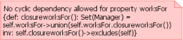
In contrast to using the pattern, Figure 2.3 shows the OCL that would have to be written to specify the constraint.
Figure 2.3. OCL for specifying that cyclic dependency is not allowed for the Manager
Service Provider Pattern4
Next, consider a situation where we are creating SOA-based solutions. In such a situation we can use the UML Profile for Software Services5 and then model our services and service providers. One approach is to apply the service provider stereotype to a structured class. Once the service provider has been created, we can use ports to detail the interfaces associated with the related services. Although this would be a best-practice approach, we still face a couple of issues:
• Many people are not familiar with the use of structured classes and ports.
• Even those familiar with structured classes and this approach may find it time-consuming to apply the pattern manually.
To solve these issues we can use the Service Provider pattern to assist us in representing services; an example of using the pattern is shown in Figures 2.4 and 2.5. Figure 2.4 shows a pattern instance and the model elements that have been bound to the instance. Figure 2.5 shows the resulting structured class that is created along with the ports and their associated services.
Figure 2.4. Application of the Service Provider pattern

Figure 2.5. Structured class for the ServiceProvider with associated ports for the services

Master-Detail Pattern
For a final example, let’s look at the creation of a user interface. Perhaps we want to use JSF or Struts and start to define the web pages within an application, or even a rich client interface. Although we will perform detailed UI work in a specialized tool, we can spend some time defining the set of pages, flows, and relationships and use a standard template in the resulting web page (which can then be refined).
A common approach to organizing the user interface is to create a master-detail relationship between the pages. In other words, there is a master list of elements on a page, which then provides the option to drill down to a detail page. Figure 2.6 shows a pattern instance for the Master-Detail pattern. In this case the pattern specifies that there are three roles within the pattern: Search Screen, List Screen, and Details Screen. Once the elements are bound to the roles, the pattern will add the appropriate relationships between the screens as well as the «input» MusicForm and the «list» MusicListResults.
Figure 2.6. Application of the Master-Detail pattern

From there you can either pass it to your user interface (UI) developers so they can use it as a blueprint while developing the user interface, or perhaps use a custom model-to-text pattern implementation to generate some of the UI code.
Model-to-Model Pattern Implementations
In this section we look at an example of a model-to-model pattern implementation. Model-to-model pattern implementations are usually used to derive a concrete model from a more abstract model. The example we will look at is the System Use Case to Service Collaboration pattern implementation.
System Use Case to Service Collaboration6
Unfortunately, today’s tooling does not provide us with strong visual representations of model-to-model pattern implementations. Often they surface only as a configuration file within the environment. To help you better understand the pattern, we will first provide an overview of it, then look at the associated pattern specification, and wrap up with a look at the mapping of elements from the source model to the target model.
This example comes from the SOA domain; we have created a model representing the key system use cases we have identified and want to progress to a more detailed representation as part of a service model, again applying the Software Services Profile.
Context
A direct linkage exists between the structure of the system use case model and the structure of the service model. For each system use case in the use case model there is a service collaboration in the service model, and for each flow (basic plus alternative ones) there is a service interaction under the service collaboration.
Problem
Creating the service collaborations is simple but can be tedious. We need a way to guarantee that all system use cases become service collaborations in the service model.
Solution
The pattern creates the service collaborations automatically, allowing the developer to focus on the service interaction.
Figure 2.7 provides a graphic view of the mapping of elements in the System Use Case Model to elements in the Service Model. Details on each of the mappings are as follows:
• System Use Case Model. The pattern creates a service model based on a model template, with Systems, Service Consumers, Composite Services, and Atomic Services packages.
• Subsystems. The pattern creates a UML package under the Systems package with the same name and the «subsystem» stereotype.
• System Use Cases. The pattern creates a collaboration stereotyped «serviceCollaboration» from the service profile under the corresponding package in the Systems package, containing an interaction. Both have the same name as the source element.
Figure 2.7. Mapping from System Use Case Model to Service Model

This same approach could be used to seed any lower level of abstraction from a higher one. One common example is to seed an analysis model from a use case model.
Model-to-Text Pattern Implementations
Model-to-text pattern implementations help us apply patterns as we move from a model to a text-based representation. This can be a case where we move from UML to a set of text-based artifacts such as code, documentation, configuration files, or deployment scripts.
Bean Factory Pattern Implementation7
The first example of model-to-text that we will look at uses an XML file as its input model and is based on the Java Emitter Template (JET)8 open-source technology.
Bean Factory provides an implementation of the Factory pattern for Beans classes, meaning that the Beans would be created using the factory class.
The beanPackage parameter is used to define the Java package for the Beans as well as the name of the factory. Meanwhile, the bean parameters as well as their properties are then converted into JavaBean files with the right getters and setters, and a corresponding create method is added to the factory class.
Figure 2.8 shows the application of the patterns to the Library package. The package contains two entities, Library and Book. Each of them generates a Java source file containing the Bean properties as well as the corresponding getters and setters. But more than a simple generation, the LibraryFactory is created with the methods and the source code to create the different Beans.
Figure 2.8. Application of the Bean Factory pattern implementation

Hibernate Pattern Implementation
Transformations help to generate code from UML models, but they usually don’t provide rich support for frameworks, configuration files, and associated best practices. The pattern implementation we describe here has been developed to allow the generation of Hibernate configuration files from a UML model.
In Figure 2.9 we can see that the package containing the input entities is used as the basis for the name of the Java project and the folder containing the configuration files. Then each class contained in the package leads to a resulting Hibernate configuration file; the information contained in the file is derived from the class and its relationships.
Figure 2.9. Mapping of the Hibernate pattern from model to Hibernate configuration files

Using Implementations in Combination
As we wrap up this look at examples of pattern implementations, let’s look at the result of combining the three technologies. In this example a UML pattern implementation is paired with a model-to-text pattern implementation to generate code.
The pattern implementation we will be looking at is called Requester Side Caching.9 The objective of this pattern is to increase service performance by providing a cache-aware proxy of the service on the requester side. So if the same request is executed twice, it will be served by the cache instead of being re-emitted.
The Requester Side Caching pattern implementation is composed of two steps:
- The first step uses a UML pattern implementation to bind the model elements to the pattern instance and create a
Cacheclass as well as an accelerated class implementation for the service. This is shown in Figure 2.10,10 where the accelerated service isLegacyCatalogAppand the accelerated implementation isAcceleratedLegacyCatalogApp.Figure 2.10. Requester Side Caching UML pattern implementation

Copyright IBM developerWorks, www.ibm.com/developerworks. Reused with permission.
- The second step is the application of a model-to-text implementation that will transform the modified model into Java code, not only translating the model but also filling the methods body of the
Cacheclass and of the accelerated service implementation (AcceleratedLegacyCatalogApp). The code for the caching capabilities is generated by the pattern, so the Pattern User focuses on adding the business logic to theCatalogitself.
Each step provides value; the UML pattern implementation enhances the model, and the model-to-text adds specific method content, but the true value of the pattern is realized when the two steps are combined. In addition, the composition makes the pattern more flexible. If we needed to support .NET technology, we could replace the Java model-to-text pattern implementation with a C# one.
Summary
In this chapter we looked at examples of UML, model-to-model, and model-to-text pattern implementations. We’ve seen how UML pattern implementations apply within a model, whereas model-to-model and model-to-text pattern implementations are used between models.
The examples span multiple technologies and domains, highlighting the fact that we can use pattern implementations in many situations, for many purposes, and for a range of technologies. Recall that in a PBE approach we use both pattern specifications and pattern implementations. However, in this chapter we have provided a more narrow focus, looking specifically at pattern implementations. Pattern implementations are a more recent approach to working with patterns and represent a critical aspect of PBE.