
7 Stereo
Part 1
The word ‘stereo’ comes from a Greek word meaning ‘solid’. ‘Stereoscopic vision’ means perceiving things as being solid when viewed with two eyes. Although the term ‘3D’ has become the standard (easier to spell!), ‘stereoscopy’ is still basically correct. From there it was but a small step to extend the ‘stereo’ part to sound and hence we have ‘stereophony’, or ‘stereo’ for short.
There is a sort of solidity, in a sense, when sound images are spread out in front of the listener. Here we shall deal with the usual form where there are two loudspeakers, two tracks on a tape, and so on. Actually, stereo sound could have any number of such channels – there are good reasons for saying the more the merrier – but practicalities such as economics mean that two is the norm, at least at the present. This is not to overlook the fact that there are various commercial versions which have three loudspeakers, often with the main bass speaker in the centre. This is justified on the grounds that very low frequencies are often somewhat indeterminate in their direction. However, we shall deal with two-channel systems.
In this chapter we shall consider how stereo works and look at techniques for producing stereo.
How stereo works
To begin with, we need to consider how we locate sounds in real life. A number of factors come into this, including visual clues. At first glance, one might think that the relative sound intensities at the two ears would be the major ingredient in sound location, but while this can have significance in some conditions, the single most important factor turns out to be the time of arrival difference at the two ears.
If a sound source is directly in front of a person, then there is clearly no difference in the time that sounds from this source take to arrive at the ears. In the case of a sound arriving from any direction except the front, then there will be a time-of-arrival difference. (We will not concern ourselves here with sounds which originate from above or below the level of the ears.) In the extreme case when the sound source is right at the side, i.e. 90° from the front, the time-of-arrival difference is roughly 1 ms (1 millisecond = 1/1000 second). What is rather interesting is that under fairly good listening conditions most people can detect when a sound source has moved through about 1° from the front axis, and this represents a time-of-arrival difference at the ears of roughly 10 μs – ten millionths or one hundred thousandth of a second! How the brain does this is not clear.
Time of arrival difference – In general, the sound from a particular source will arrive at a person's ears at slightly different times. This is important in detecting the apparent direction of the source.
(The question of how we locate sounds which are above or behind the head is to some extent still a little obscure. Head movements help to pin down the source of a sound. Most people turn to try to look at the source of a sound and for each head movement the brain can carry out computations which enable the listener to narrow down the uncertainty. Also, there is evidence that the folds in the outer ear – the visible portion – may create multiple reflections at high frequencies and the pattern of these reflections will depend on the angle of incidence of the sound.)
It follows that to recreate directional information for a listener, at least in a frontal area, we need to create time-of-arrival differences at the person's ears.
Assuming that the listener will be sitting in front of a pair of loudspeakers, and equidistant from them, there can be no significant time-of-arrival differences at the person's ears. Can they be created in the studio? At first sight, this would seem to be the obvious thing to do and in fact this was what was done in the early days of commercial stereo by spacing the microphones some distance apart. Unfortunately, this does not usually work at all well. With a pair of microphones spaced, say, a couple of metres or more apart, the listener is apt to hear two separate sound images, one at each loudspeaker and nothing in between – a situation usually described as hole-in-the-middle or ‘ping pong’ stereo. (Agreeable stereo can be produced if the microphones are not too widely spaced – perhaps no more than a metre.)
Now it so happens that if the electrical signals in the two channels – the left and right paths from microphones to loudspeakers – differ from each other only in amplitude, then a reasonable spread of sound images between the loudspeakers can be expected. The explanation for this is beyond the scope of this book, but there are readable explanations in some of the books listed at the end. At the moment, we will simply state that, for loudspeaker listening, there need to be amplitude differences between the two channels – inter-channel differences – and paradoxically, no timing differences, between the signals in them.
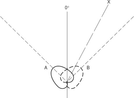
Figure 7.1 A coincident pair of cardioid microphones
Methods of producing inter-channel differences
Broadly there are two techniques, although in practice their usage often overlaps. These are:
1. Using a pair of directional microphones very close together. They are angled symmetrically about an imaginary line which points to the centre of the recording area. Figure 7.1 shows two cardioid microphones positioned in this way. A pair of microphones with the diaphragms as close together as possible form what is known as a coincident pair.
If sounds arrive from directly in front of the two microphones – 0° in the diagram – then both microphones will receive the same sound levels and the outputs will be exactly equal. (It is very important that the two microphones are closely matched in performance. The same is also true of loudspeakers in stereo.)
A sound arriving off the centre axis of the microphones, say from X in the diagram, will result in a larger output from the right-hand microphone than from the left-hand one and this then gives us the required inter-channel difference.

2. Purely electrical methods. Figure 7.2 shows in simplified form what is termed a panpot (from ‘panoramic potentiometer’). A potentiometer is a variable electrical resistance with three terminals. Two are at the ends of a resistive track, while the third is connected to a slider whose position along the track may be varied by means of a knob.
Coincident pair – Two directional microphones with their diaphragms mounted as close together as possible.
The position of the slider, which in this case is connected to the output of a microphone, determines what proportion of the microphone's output is fed to which channel. This then gives us a second way of producing inter-channel differences.
Terminology
It is more or less universal in the UK professional world to use the following conventions in stereo:
The LEFT channel is denoted by the letter A and, where appropriate, the colour RED is used to indicate this – for example, on cables and in diagrams.
The RIGHT channel is indicated by the letter B and the colour is GREEN.
This professional convention is easily remembered: in writing the alphabet A is on the LEFT of B; in navigation RED indicates port (LEFT) while GREEN means starboard or RIGHT.
Note, however, that on domestic equipment L and R are normally used for left and right, and also the colour convention is different: WHITE is commonly used for LEFT and RED for RIGHT. To add to the confusion, headphones may have YELLOW for left, with RED still for right.
Stereo listening
We have already implied that the listener should be on the centre line between the two loudspeakers and that these should be a ‘matched’ pair. And not only should they be matched in quality terms, but they must be ‘balanced’ so that if fed with exactly the same signal (i.e. mono) the resultant sound image is truly central. (How to check on the matching is explained below, as are ways of obtaining a mono signal.)
If the balance is incorrect it is then a matter of putting this right by either adjusting the gain (volume) controls on the amplifiers feeding the loudspeakers or adjusting the balance control if there is one, as there usually is on decent home hi-fi equipment.
The ideal listening position, then, is at the apex of an equilateral triangle formed by the listener and the loudspeakers, but in practice the listener can be further back from this point. How much further back depends on circumstances, mainly the shape, size and symmetry of the room.
The ideal listening room will be acoustically symmetrical between left and right. For example, it is undesirable to have a bare wall on one side and a window with heavy curtains over it on the other side. If the listener is not too far from the loudspeakers, some lack of symmetry may not be too serious as the direct sound from the loudspeakers will be much stronger at the ears than sound reflected from the walls. However, the further back the listener gets, the greater the influence of reflected sounds is likely to be. Few rooms can be truly symmetrical, so that there is a limit to the distance from the loudspeakers at which good stereo is heard.
The loudspeakers should not be too close to the walls. In many circumstances about half a metre from the back wall can be acceptable, and the space between them should not be reflective to sound. In a domestic situation, this can be difficult to achieve, although in the author's sitting room the space between the loudspeakers is filled by a fireplace designed deliberately to look like a traditional Cotswold stone wall. This seems to be perfectly satisfactory, possibly because there are sufficient irregularities to break up at least some of any reflected waves, and also the edges of the limestone pieces may be slightly absorbent to sound waves.
One notably unsatisfactory listening position is closer than the apex of the equilateral triangle, as images may become somewhat unreal. It can be a little like listening to stereo headphones.

Figure 7.3 Listening positions
Having said that the listener should be on the centre line between the loudspeakers, a reasonable question to ask is, how far off this centre line can the listener be before stereo images become excessively left-or right-handed? The answer in brief is that for really critical listening there is very little latitude indeed, perhaps 2 or 3 cm, with a loudspeaker spacing of a couple of metres. However, there can be pleasing stereo listening, which is a different matter, when the listener is noticeably off the centre line. Much can depend on the particular loudspeakers. Some types will give a reasonable spread of sound when the listener is a metre or more off the centre line, assuming again a 2-metre base line.
A few words of reassurance about listening
Some of what has been written above could easily seem very worrying to the ordinary person who simply likes to listen to reasonable stereo. To such a person we would simply say, ‘Don't worry!’ Don't rearrange your sitting room to make it acoustically symmetrical; don't fill in a window or curtain a facing wall. If you have enjoyed your music up to now then go on enjoying it. (In a professional environment, though, there will have to be more care taken in designing listening areas.)
It might be, of course, that peculiar imaging has been a problem and there are hints here that might help. It's rather like the cases in my own experience when people with loudspeakers of which they were very proud had the loudspeaker responses measured. The almost inevitably uneven graphs caused great distress – really quite unnecessarily. These were cases of a little knowledge being, not dangerous, but disturbing – or perhaps one could say that mild ignorance was bliss!
Stereo loudspeaker matching
This means ensuring that the quality of output of the two loudspeakers is as near as possible the same. The best way of checking this is to feed both loudspeakers with mono music which contains a wide range of frequencies.
Assuming the loudspeakers are balanced in loudness then all frequencies should appear to come from mid-way between them. If, however, this is not the case and, to take an example, the high frequencies come from a point to the right of the centre, it means that there is excessive high frequency output from the right loudspeaker or, and much more likely, there is a high frequency deficiency from the left loudspeaker. A possibility in that case is that the tweeter of that loudspeaker is faulty.
We have said rather glibly that the easiest way of checking the matching, and also the balance, of the loudspeakers is to feed them with mono music. The trouble is that it may not always be easy to find a source of mono music! Professional equipment is usually provided with a switch which can convert stereo material into mono for purposes such as this. Home equipment often does not. The problem is not, however, insuperable. Some radio receivers intended for connection into a hi-fi system have a mono/stereo button to be used when the broadcast stereo is weak and noisy but the mono version is acceptable. This could be used to provide either mono music directly or a mono music tape.
Things become a little more difficult if there is no mono/stereo button. A partial solution, albeit without a wide frequency range, is to tune the receiver to a news broadcast when the newsreader will almost certainly be central and therefore mono.
Phase
This means, in essence, that the polarity of the wiring is the same in both channels of a stereo system. Figure 7.4 illustrates this.
In Figure 7.4(b) the electrical connections have, at some point, been reversed in ONE of the channels. The effect is that a sound wave compression is emitted from one loudspeaker when a rarefaction is emitted from the other. This is a very unnatural effect for a listener, being something that does not occur in real life, or if it does, only briefly and incompletely.
The result of out-of-phase stereo is that images are very difficult to locate. They may appear to come from behind or even inside the head and they are apt to move if there is any attempt to locate them by turning the head. It is not generally a pleasant experience and prolonged listening to out-of-phase stereo can induce a headache. There have even been reported instances of physical nausea.

Figure 7.4 (a) Correct phasing (b) Incorrect phasing
How obvious an out-of-phase condition is can depend very much on the type of programme material. With wide stereo images and little central sound an out-of-phase signal may not be at all obvious. It will be most apparent with mono or central images. This, then, is the way to check for out-of-phase connections. Play a central mono signal (and here a simple news bulletin will be quite adequate) and check that there is a clear central image. If there is any doubt then the wiring of one of the channels should be changed over, and probably the easiest way of doing this will be at the terminals of one of the loudspeakers. If the system is found to be out of phase, and the wiring to the loudspeakers is obviously correct, it will be necessary to check through the rest of the system. This will be an especially useful exercise if other equipment is likely to be added.
Questions
1. What is the approximate time-of-arrival difference at the two ears of a person when a sound source is 90° from the front?
a. 10 μs |
b. 0.01 ms |
c. 0.1 ms |
d. 1 ms |
2. What is a likely cause of ‘hole-in-the-middle’ stereo?
a. |
Out-of-phase conditions |
b. |
Microphones too widely spaced |
c. |
Signals in one channel being much larger than in the other channel |
d. |
Mismatched loudspeakers |
3. A panpot is set with its control fully clockwise. Where is the image from it likely to be in the final stereo image?
| a. Fully right | b. Fully left | c. Half right | d. Half left |
4. What should be a clear central image in a stereo scene is difficult to locate by listening. What is the likely cause?
a. |
There is an out-of-phase condition somewhere |
b. |
Panpots are being used incorrectly |
c. |
A coincident pair microphone is mounted upside down |
d. |
One of the microphones is distorting |