Chapter 19
Computer-Aided Quality Control
19.1 Introduction
The quality control (QC) function has traditionally been performed using manual inspection methods and statistical sampling procedures. Manual inspection is generally a time-consuming procedure which involves precise, yet monotonous work. If often requires that parts be removed from the vicinity of the production machines to a separate inspection area. This causes delays and often constitutes a bottleneck in the manufacturing schedule.
Inherent in the use of statistical sampling procedures is acknowledgment of the risk that some defective parts will slip through. Indeed, statistical quality control attempts to guarantee that a certain expected or average fraction defect rate will be generated during the production/inspection process. The nature of traditional statistical QC procedures is that something less than 100% good quality must be tolerated.
There is another aspect of the traditional QC inspection process which detracts from its usefulness. It is often performed after the fact. The measurements are taken and the quality is determined after the parts are already made. If the parts are defective, they must be scrapped or reworked at a cost which is often greater than their original cost to manufacture.
There are several economic, social, and technological factors at work to modernize the quality control function. The economic factors include the high cost of the inspection process as it is currently done and the desire to eliminate inspection as a source of costly delay in production. The social factors include the ever-increasing demand by customers for near perfection in the quality of manufactured items, the growing number of expensive product-liability legal cases, and government regulations which require many firms to maintain comprehensive production and quality records. Another factor in this category is the tendency for some manual inspection tasks to involve subjective judgment on the part of the human inspector. It is considered desirable to try to remove this subjective component from inspection operations. Finally, the technological factors consist of several important advances which have been made in inspection automation. Principal among these advances have been the tremendous growth in the application of microprocessors and improvements in noncontact sensor techniques such as vision systems.
All of these various factors are driving the quality control function toward what we are calling computer-aided quality control (CAQC). Other terms that have been applied to describe this movement are “computer-aided inspection” (CAI) and “computer-aided testing” (CAT). As we describe in Section 19.3, CAI and CAT are subsets of CAQC.
The objectives of computer-aided quality control are ambitious, yet straightforward. They are:
1.To improve product quality
2.To increase productivity in the inspection process
3.To increase productivity and reduce lead times in manufacturing
The strategy for achieving these objectives is basically to automate the inspection process through the application of computers combined with advanced sensor technology. Wherever technically possible and economically feasible, inspection will be done on a 100% basis rather than sampling. It will be done on-line almost as part of the production operations. On-line 100% inspection will introduce opportunities to use the inspection measurements as feedback data to make compensating adjustments in the manufacturing process.
In this chapter we explore the topic of computer-aided quality control. The discussion includes many of the latest developments in both contact and noncontact inspection techniques. We also consider the way the quality control function should make use of the CAD/CAM data base. To begin with, let us consider some of the basic terminology in quality control.
19.2 Terminology In Quality Control
In many respects, computer-aided quality control represents a significant departure from the traditional QC methods. Nevertheless, the terminology is similar, and it is appropriate to review the various terms and concepts used in this field before examining the role played by the computer.
Quality in a manufacturing context can be defined as the degree to which a product or its components conform to certain standards that have been specified by the designer. The design standards generally relate to the materials, dimensions and tolerances, appearance, performance, reliability, and any other measurable characteristic of the product.
To ensure that its products adhere to the specified standards, a firm will generally organize its activities along two approaches: quality assurance and quality control. These two approaches represent the before and after in the firm’s efforts to manage quality in manufacturing.
Quality assurance (QA) is concerned with those activities which will maximize the probability that the product and its components will be manufactured within the design specifications. These activities should start in the product design area, where the designer can make decisions among alternatives that might have quality consequences. For example, the decision might be between two or more materials to specify for a particular component. The designer must select the material that will achieve the best performance (in terms of properties, durability, reliability, processability, etc.) relative to its cost. QA activities continue in manufacturing planning, where decisions relative to production equipment, tooling, methods, and motivation of employees will all have an influence on quality.
Quality control is concerned with those activities related to inspection of product and component quality, detection of poor quality, and corrective action necessary to eliminate poor quality. These activities also involve the planning of inspection procedures and the specification of the gages and measuring instruments needed to perform the inspections. Included within the scope of planning would be the design of statistical sampling plans, a field of study which is usually called statistical quality control.
Statistical QC is generally divided into two categories: acceptance sampling and control charts. Acceptance sampling is a procedure in which a sample is drawn from a batch of parts in order to assess the quality level of the batch and to determine whether the batch should be accepted or rejected. A company can apply the procedure to items received from a supplier or to items of its own manufacture. Acceptance sampling is based on the statistical notion that the quality of a random sample drawn from a larger population will be representative of the quality of that population.
The application of control charts derives from the same statistical concept. Control charts are used to keep a record over time of certain measured data collected from a process. A company would use control charts to monitor its own production processes. A general form of the control chart is illustrated in Figure 19.1.
Figure 19.1 General form of a control chart used in a statistical quality control.
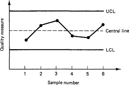
The central line indicates the expected quality level of the process. The upper and lower control limits (UCL and LCL) are statistical measures of the variation in the process which would be tolerated without concluding that the process has erred. When these limits are exceeded, it usually means that something has changed the process, and an investigation should be initiated to determine the cause. Whereas acceptance sampling is applied to a batch of product after it is completed, control charts are applied during production. This means that it is possible with control charts to make adjustments in the manufacturing process if the recorded data indicate that corrections are needed.
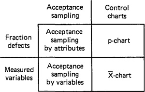
Both acceptance sampling and control charts can be applied to two situations in quality control: fraction defects and measured variables. The combination of possibilities is shown in Figure 19.2 together with the names commonly given to the sampling methods. In the fraction-defect case, the objective is to determine what proportion of the sample (and the population from which it came) are defective. This is often accomplished by a go/no go gage, which can quickly determine whether a part is within specification or not. In the measured-variable case, the object is to determine the value of the quality characteristic of interest (e.g., dimension, resistance, hardness, etc.). This requires the use of a measuring instrument of some kind (e.g., micrometer, ohmeter, hardness tester, etc.) and is normally a more time-consuming manual process than the go/no go case.
Figure 19.2 Types of statistical QC procedures.
A final distinction that should be made is the difference between inspection and testing. Although the common usage of these terms often overlaps, we will distinguish them as follows. Inspection is normally used to examine a component of a product in relation to the design standards specified for it. For a mechanical component, this would probably be concerned with the dimensions of the part. These might be checked with several go/no go gages or they might be measured with a micrometer and other instruments. Inspection should be done whenever and wherever the expected costs of not inspecting (e.g., scrap, rework, loss of customer good will) exceed the cost of inspecting. The common situations that warrant inspection are:
Incoming raw materials
At various stages during manufacturing (e.g., when the parts are moved from
one production department to another)
At the completion of processing on the parts
Before shipping the final assembled product to the customer
Testing, on the other hand, is normally associated with the functional aspects of the item, and it is often directed at the final product rather than its components. In this usage, testing consists of the observation of the final product during operation under actual or simulated conditions. If the product passes the test, it is deemed suitable for sale. Harrington (5) lists several categories of tests used for final product evaluation:
Simple functional tests under normal or simulated normal operating
conditions
Functional tests in which the product is tested under extreme (usually adverse)
conditions
Fatigue or wear tests to determine how long the product will function until failure
Overload tests to determine the level of safety factor built into the product
Environmental testing to determine how well the product will perform under
different environments (e.g., humidity, temperature)
Another type of testing that is often mentioned is destructive testing. This is a procedure that results in the destruction of the item in order to measure the property of interest. A common example is the tensile test on a specimen of metal to determine the metal’s strength and ductility properties. Destructive testing is often employed as an inspection procedure, the way we have defined it, because it is often applied to raw materials, partially processed materials, and component parts. It can also be applied to the final product, as might be suggested by Harrington’s list of tests. However, destructive testing for final products is expensive and would be done on a very limited sampling basis.
19.3 The Computer In Qc
Computer-aided inspection (CAI) and computer-aided testing (CAT) are merely extensions of their counterparts described above. Whereas these activities have traditionally been performed manually (with the help of gages, measuring devices, and testing apparatus), CAJ and CAT are performed automatically using the latest computer and sensor technology. Computer-assisted inspection and testing methods form only part, certainly a major part, of computer-aided quality control. In our treatment of the subject we shall include the integration of the quality control function with CAD/CAM as a critical ingredient in the success of CAQC. CAI and CAT are examples of what have been called “islands of automation.” They are stand-alone systems. Without their integration into larger computerized systems, CAQC will not achieve its full potential.
The implications of the use of computer-aided quality control are important. The automated methods of CAQC will result in significant changes from the traditional concepts and methods described above. Critical changes will also occur in the way the quality function is implemented within a company. We have already alluded to some of the changes. The following list will summarize the important effects likely to result from CAQC.
1. With CAI and CAT, inspection and testing will typically be accomplished on a 100% basis rather than by the sampling procedures normally used in traditional QC.
2. Inspection during production will be integrated into the manufacturing process rather than requiring that the parts be taken to some inspection area. This will help to reduce the elapsed time to complete the parts. Also, to incorporate online inspection into the production process will mean that inspection will have to be accomplished in much less time than with current manual techniques. How will this improvement in inspection productivity be achieved? The third point below addresses this question.
3. The use of noncontact sensors will become much more widely used with computer-aided inspection. With contact inspection devices, the part must usually be stopped and often repositioned to allow the inspection device to be applied properly. Stopping, repositioning, and making physical contact with the part all take time. With noncontact sensor devices, the part can often be inspected “on the fly.” These devices, driven by the high-speed data processing capability of the computer, can complete the inspection in a small fraction of a second. This is a rate which is certainly compatible with most production operations.
4. The on-line noncontact sensors will be utilized as the measurement component of computerized feedback control systems. These systems will be capable of making adjustments to the process variables based on analysis of the data collected by the sensors. The data analysis would include statistical trend analysis. An example of the need for trend analysis can be found in the gradual wear of cutting tools in a machining operation. Data would be plotted (even if only in computer memory) on a control chart similar to Figure 19.1. This would not only allow out-of-tolerance conditions to be identified, but gradual shifts in the process could also be uncovered and corrective action taken. By regulating the process in this manner, parts will be made much closer to the desired nominal dimension rather than merely within tolerance. Quality feedback control systems will help to reduce scrap losses and improve product quality.
5. Because 100% inspection and on-line quality control systems will become prevalent, a basic assumption in statistical QC must be challenged. That is the assumption that anything less than 100% good quality is acceptable. The use of statistical quality control tolerates less than 100% perfect quality. With computer-aided inspection technology, it may no longer be necessary to settle for less than perfection.
6. Sensor technology will not be the only manifestation of automation in CAQC. Robots will be used increasingly in future inspection applications. We discussed these applications in Section 11.8. Also, completely automated test cells will become an important component in future factories.
7. In addition to CAI and CAT, the computer will be used in other areas of quality control. There will also be applications for the computer in quality assurance as well as QC. The CAD/CAM data base will be used to derive these various quality applications, and we discuss some of the possibilities in Section 19.8.
8. There will be personnel implications in CAQC. To the extent that CAI and CAT take its place, manual inspection activity will be reduced. Quality control personnel will have to become more computer-wise and technologically sophisticated to operate the more complex inspection and testing equipment and to manage the information that will result from these more automated methods.
In the following three sections we consider various types of modern contact and noncontact inspection techniques. The contact methods usually involve the use of coordinate measuring machines (CMM). Most of these machines today are either controlled by NC or computers. The noncontact methods are divided into two categories for our purposes: optical and nonoptical. The optical methods usually involve some sort of vision system, although other methods, such as lasers, are also used. The nonoptical techniques are typically based on the use of electrical fields to sense the desired characteristic of the object. Ultrasonics and radiation represent other possible sensor technologies. The classification of the various types of sensors is presented in Table 19.1.
In the final two sections of the chapter we discuss computer-aided testing and the integration of CAQC with CAD/CAM, in particular, the use that might be made of the CAD/CAM data base in quality control.
Table 19.1 Classification of Inspection Sensor Technologies

19.4 Contact Inspection Methods
The coordinate measuring machine (CMM) is the most prominent example of the equipment used for contact inspection of workparts. A coordinate measuring machine is illustrated in Figure 19.3. It consists of a table which holds the part in a fixed, registered position and a movable head which holds a sensing probe. The probe can be moved in three directions, corresponding to the x, y, and z coordinates. During operation, the probe is brought into contact with the part surface to be measured and the three coordinate positions are indicated to a high level of accuracy. Typical accuracies of these machines are in the neighborhood of +0.0002 in. (0.0051 mm).
Today’s coordinate measuring machines are computer controlled. The operation of the machine is similar to an NC machine tool in which the movement of the measuring probe is either tape controlled or computer controlled. Programs and coordinate data can be downloaded from a central computer, much in the manner of direct numerical control. Also similar to DNC is the capability to transmit data from the CMM back up to the host computer.
Recent advances in CMM technology are based largely on greater intelligence and convenience features provided by the computer. These advances include the capability for automatic workpart alignment on the machine table, interactive programming of the CMM for inspection personnel who are inexperienced in the
Figure 19.3 Coordinate measuring machine. (Courtesy of Automation and Measurement Division, Bendix Corp.)

use of computers, and conversion routines between polar and cartesian coordinate systems.
Savings in inspection time by using coordinate measuring machines are significant. Typically, between 5 and 10% of the time is required on a CMM compared to traditional manual inspection methods. Other advantages include consistency in the inspection process from one part to the next which cannot be matched by manual inspection, and reductions in production delays to get approval of the first workpiece in a batch.
Although the reductions in inspection time are significant with a CMM, there is nevertheless wasted time associated with the fact that the coordinate measuring machine is physically located away from the production machine, usually in a separate area of the shop. Accordingly, the parts must be transported from the production area to the CMM. In fact, if inspection is required at several different stages of production, several moves will be involved. One possible approach to overcome this problem is to use inspection probes mounted in the spindle of the machine tool. These inspection probes are contact sensing devices that operate with the machine tool much like the coordinate measuring machine. We have already discussed inspection probes in connection with numerical control and the reader is referred back to Section 9.8 and to Figure 9.10, which shows an example of an inspection probe.
19.5 Noncontact Inspection Methods-Optical
Noncontact inspection of items is an attractive alternative to the types of methods discussed in the preceding section. Among the advantages of noncontact inspection are [11]:
It usually eliminates the need to reposition the workpart.
Noncontact inspection is usually much faster than contact inspection.
It eliminates mechanical wear encountered with the contacting inspection probe because it eliminates the probe.
It reduces potential danger to people, who must touch a hazardous material if contact inspection is used.
It removes the possibility of damage to the surface of a part which might result during contact inspection.
We divide the varieties of noncontact inspection schemes into two categories: optical and nonoptical. This section covers the different types of optical inspection devices available. The next section covers the nonoptical category.
Optical systems are the dominant type of noncontact inspection method. These systems generally rely on the use of microelectronics technology and computer processing of the sensing signals. Improvements in performance and reductions in cost in these two areas are making optical systems more and more economically feasible. There are a variety of optical sensing techniques used for inspection work. We shall discuss three types:
1. Machine vision
2. Scanning laser beam devices
3. Photogrammetry
All of these optical systems use some form of light sensor or photosensitive material. Simple light-sensing systems use photocells, photodiodes, and photographic paper.
Machine vision
The use of machine vision systems for inspection is an exciting area which holds the promise of significant improvements in both the productivity of the inspection process and the quality of the resulting product. Other names given to these systems include microprocessor-based television and computer vision. The typical machine vision system consists of a TV camera, a digital computer, and an interface between them that functions as a preprocessor. The combination of system hardware and software digitizes the picture and analyzes the image by comparing it with data stored in memory. The data are often in the form of a limited number of models of the objects which are to be inspected.
The technology of machine vision inspection is one in which advancements and refinements are continually being made. At the time of this writing, there are several limitations of machine vision which are imposed principally by current computer speed and storage technology. The first limitation is concerned with the problem of dividing the picture into picture elements. This is very similar to the problem encountered in the development of graphics terminals for computer-aided design (Section 5.3). Most machine vision systems in use today have a picture area consisting of roughly 240 by 240 pixels. (There are variations in these numbers for commercially available systems.) In terms of image resolution, this represents a very limited capability to accomplish precise measurements and analyze complex images. Future improvements in vision technology will allow the number of picture elements in machine vision systems to be substantially increased for better image resolution.
A second limitation is that the object in front of the camera must be capable of being divided into areas of contrasting lightness and darkness. Most commercial systems today divide the image into two states, black and white. Gray areas must be interpreted as being either black or white, depending on their relative level of brightness. This is done by selecting a threshold brightness level and assigning each picture element to one of the two states depending on whether its brightness is greater than or less than the threshold level. This limitation imposes requirements on the lighting that must be used to illuminate the object. The requirement is sometimes satisfied by backlighting the object to accentuate the contrast between the object and surrounding areas.
Third, there are limitations on the capability of machine vision systems to recognize the object in the viewing area. For example, the number of distinct objects that can be recognized by the system is limited by its ability to discriminate features of different objects and by its computer storage capability. The features of an object which can be determined by a typical vision system include area, perimeter, center of gravity, the dimensions of an enclosing geometric form such as a circle, and certain directional features such as the line passing through the two centers of an ellipse. The storage capability restricts the amount of data and the number of separate models that can be compared with the image. Another difficulty is in the ability of the system to deal with variations in the image. Such variations might represent defects in the object that should be identified in the inspection process, or they might be variations in part orientation and position. Part orientation and position problems can be readily solved by today’s vision inspection technology. For example, the orientation problem can be solved by using the directional features of the object to adjust for differences in rotation of the part. One of the problems which still remains is when parts in the viewing area overlap one another so that the system is unable to identify the outline of each part.
These various limitations are expected to be gradually reduced as the technology develops during the next several years. Future machine vision systems will have better image resolution, greater ability to distinguish grey areas and even color, and more intelligence and memory for improved object recognition capability.
There are a wide variety of inspection problems that can be solved by current day machine vision systems. The solutions are often individualized to the particular inspection problem. Collectively, they represent the scientific and engineering efforts of many different companies and research laboratories in this fast developing industry. Machine vision inspection problems can be divided into two categories [13]:
1. Noncontact gaging of dimensions
2. Inspection based on pattern recognition of object features
Noncontact gaging in machine vision involves the inspection of part size and other features where it is not necessary to process the image of the entire part outline, only those portions that must be examined for dimensional accuracy. During setup for an inspection, a parts-training program is used to view the workpart of interest on a TV monitor. With the image in fixed position on the screen, the operator manipulates a cursor to define the edges of interest and to apply an appropriate scale factor to establish the correct units of measure. During actual inspection, the vision system identifies the relevant boundaries so that the desired dimensions of the part can be scaled for automatic gaging. The inherent limitation of the scaling accuracy of the system is determined by such factors as the density of picture elements in the viewing area (the first limitation of present day machine vision systems discussed above) and the field of view of the TV camera.
The second category of machine vision inspection is based on pattern recognition techniques. In this category, the attributes of the object to be inspected are typically more subjective and in some respects more complicated than part dimensions. The machine vision pattern recognition process can be conceptualized as involving a comparison of features (for example, area, perimeter, and so on) between the object being inspected and the model of the object stored in computer memory. One of the techniques that is sometimes applied in pattern recognition is called automatic edge detection [6]. In machine vision edge detection, the problem is to distinguish the boundaries between light and dark areas in the image. These boundaries indicate prominent part features such as edges and holes. Based on the results of the edge detection process, the system can be programmed to compute object features such as surface area, number of holes, hole area, perimeter, and center of gravity. Correction routines must be programmed into the pattern recognition software to compensate for nuisances such as statistical variations in the images, part misalignment, and variances in part orientation. Examples of the kinds of inspections in this second category include:
Inspection of labels on bottles and cartons. In the case of clear bottles, machine vision systems have been programmed to inspect the level of the contents in the bottles.
Optical character recognition problems
Inspection of the gross outline of parts
Inspecting for the presence or absence of features in an assembled product.
The electronics manufacturing industry has made significant contributions to the development of these techniques [3]. Printed circuit boards, for example, can be inspected for potential defects such as short circuits, missing holes, over-etching and under-etching. Other applications in electronics include inspection of microcircuit photomasks and semiconductor chip inspection. Inspecting for cracks and other imperfections in work surfaces
An example of the kind of commercially available vision system that can perform inspections based on pattern recognition is shown in Figure 19.4. The TV camera in the foreground is focused on a small portion of the bottle label and the image is displayed on the television monitor.
Automatic vision systems and other types of optical sensors used for inspection are often built into the production line to operate with some form of parts rejection mechanism. As the image is processed, the system makes a determination as to whether the part is good or reject. If good, the part proceeds to the next processing
Figure 19.4 Vision system showing camera (in foreground), control console, and TV monitor. (Courtesy of Object Recognition Systems, Inc.)

station. If reject, the automatic rejection mechanism is triggered to eject the part into a separate location.
Machine vision systems using pattern recognition techniques have been applied in areas other than manufacturing inspection. Two primary examples are the processing of satellite images and the analysis of medical (for example, x-ray) images. Another application is in robotics, where the vision system is utilized as a sophisticated feedback control sensor for actions that are to be carried out by the robot. We have previously discussed this application in Section 10.9.
Scanning laser beam devices
Not all scanning beam devices use lasers as the light source, but most of them do. The advantage of the laser is that it is a coherent light beam which can be projected great distances without significant diffusion. Lasers have found many applications in industrial measurement problems.
The scanning laser beam device relies on the measurement of time rather than light, although a light sensor is required in its operation. The schematic diagram of its operation is pictured in Figure 19.5. A laser is used to project a continuous thin beam of light. A rotating mirror deflects the beam so that it sweeps across the object to be measured. The light sensor is located at the focal point of
Figure 19.5 Schematic diagram showing laser beam system.

the lens system to detect the interruption of the light beam as it is blocked by the object. The time lapse corresponding to the interruption of the light beam is measured to determine the desired dimension of the part. Typically, a microprocessor is programmed to make the conversion of the time lapse into a dimensional value and to perform other functions, such as signaling an automatic parts-rejection mechanism to eject a defective part from the line.
Photogrammetry
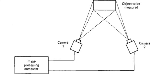
Photogrammetry is a technique which may gain in usage in inspection work as it is perfected. The term refers to a procedure which was borrowed from aerial reconnaisance and geological mapping applications. A more recent application of the procedure is in aerospace plants to measure large airframe assembly fixtures.
Photogrammetry involves the extraction of three-dimensional data from a pair of photographs taken at different angles. The two photographs can be combined much in the way that a stereoscope uses a pair of photographs to form a three-dimensional image for the viewer.
In the measurement process used for inspection, the two photographs are read by a device called a monocomparator to establish coordinates and positions of objects. These data are then computer-analyzed to extricate the desired information.
The drawback of the conventional photogrammetry technique is the need for photographs, an inconvenient and time-consuming step in the procedure. An improvement in the technique which is being developed will delete the photographic step. Instead, the images from two cameras set up in a stereoscopic configuration will send visual data directly to a computer for mathematical analysis and real-time extraction of dimensional data. This arrangement is illustrated in Figure 19.6.
Figure 19.6 Measurement system based on photogrammetry principles.
There are a wide variety of approaches to optical sensing systems for non-contact inspection. We have described only three of the techniques to give an idea of the variety available. A particularly good review of the range of available systems is presented in an article by Schaffer [11]. Written in 1979, the article may be slightly dated at present in such a fast-moving technology. Comforting, however, is the fact that the physical principles remain fairly constant.
19.6 Noncontact Inspection Methods– Nonoptical
In addition to noncontact inspection methods based on optical systems, nonoptical approaches can also be used. We will describe three general types which are quite representative of the current technology in this area. The three general types are:
1. Electrical field techniques
2. Radiation techniques
3. Ultrasonics
Electrical field techniques
Various types of electrical field techniques can be applied to noncontact inspection. Three types of electrical fields are employed:
1. Reluctance
2. Capacitance
3. Inductance
The reluctance transducers are proximity devices that indicate the presence and distance from the probe of a ferromagnetic substance. The obvious limitation of the device is that the object being inspected must be electromagnetic.
A capacitance-based transducer can also be used to measure the distance of an object from the face of a probe. The measurement is based on the variable capacitance from part/probe coupling. This capacitance is inversely proportional to the distance between the probe face and the part, and thus the distance can be calculated. The capacitance transducer can be used to detect a variety of materials. The material must be an electrical conductor.
Inductance systems operate by subjecting the object to an alternating magnetic field by means of an electromagnetic coil. The result is that small circulating currents (eddy currents) are generated in the object. These eddy currents, in turn, create their own magnetic field, which interacts with the primary field. This interaction affects the impedance of the coil, which can be measured and analyzed to determine certain characteristics about the object.
In all three cases, the object to be inspected is placed in the electrical field and its effect is observed and analyzed. Typically, the location of the object is measured in reference to the probe which is generating the electrical field. In some arrangements, two probes must be used. Location, part dimensions, part thickness, and other characteristics can be measured depending on the inspection setup. Eddy-current-based systems can be utilized to inspect below the surface of an object to detect cracks, voids, and other flaws in metals.
Radiation techniques
X-ray radiation techniques are employed for purposes of noncontact inspection in the metals and metalworking industry. The amount of radiation absorbed by a material can be used to measure its thickness and other quality characteristics. In a typical application in a rolling mill, an X-ray scanning unit measures the thickness of the plates or strips going through the rolls so that the proper adjustments can be made in the rollers. X-ray techniques are also used to inspect weld quality in fabricated steel and aluminum pressure vessels and pipes. In this case the radiation can be used to detect flaws and voids in the weld.
Ultrasonics
Ultrasonics in inspection work involves the use of very high frequency (above 20,000 Hz) sound waves to indicate quality. A principal application is in nondestructive testing of materials. Ultrasonic techniques can also be applied to the problem of determining dimensional features of workparts. One approach, called acoustical phase monitoring, involves the analysis of sound waves reflected from the surface of an object. The sound waves are produced by an emitter and directed against the object. Assuming that all else remains constant, the reflected sound pattern from the object should always be the same. During inspection, the sound pattern from the part is analyzed by a computer program and compared to the pattern of a standard part, one that is known to be of acceptable quality. If the pattern of the test part differs significantly from that of the standard, it is rejected.
19.7 Computer-Aided Testing
As described in Section 19.2, testing is generally applied to assess the functional performance of a final product. It may also be applied for major subassemblies of the final product, such as the engines and transmissions of automobiles. Testing may also be performed on individual components in which some functional aspect of the component must be examined and cannot be implicitly determined by means of a mechanical inspection. An example of this might be the case of a brake lining in which the dimensions are correct, but the functional performance must be determined through a testing procedure.
Computer-aided testing is simply the application of the computer in the testing procedure. There are different levels of automation which can be found in CAT. At the lowest level, the computer would be used simply to monitor the test and analyze the results, but the testing procedure itself is manually set up, initiated, and controlled by a human operator. In this case the computer receives the data from a data logger or a data acquisition system (refer to Section 16.6) and prepares a report of the test results.
At a much higher level of automation are computer-integrated test cells, which consist of a series of testing stations (a dozen or more stations is not uncommon) interconnected by a materials handling system. An automated test cell has most of the earmarks of a computer-integrated manufacturing system of the type to be discussed in Chapter 20. These cells are often interfaced directly to the assembly line so that the products flow automatically from final assembly to final testing. All facets of the operation of the test cell are under computer control. The individual stations typically operate independently of each other. During operation, a product is transferred by the handling system to an available test station. The test station automatically registers the product in the proper location and orientation, and attaches the required connecting apparatus to conduct the test. The testing then begins with the computer monitoring the data and analyzing the results. If the product passes the test, it is automatically moved to the next assembly operation or final packing. In the event the product fails to pass the test, there is often the provision to transfer the product to a manual station for examination by a human operator. The computer can often be helpful in this regard by indicating the reason the test failed, or even diagnosing the problem and recommending the most promising repair alternative. Another feature of some test cells is the capability to make adjustments in the product during the test cycle to fine-tune its functional operation.
Computer-aided test cells of the type described above are applied in situations where the product is complicated and produced in significant quantities. Examples include automobile engines, aircraft engines, and electronic integrated circuits. Advantages of these cells include higher throughput rates, greater consistency in the test procedure, and less floor space occupied by the automated cell as compared to a manual facility of similar capacity.
Example 19.1
An example of a large test cell is the automatic hot test system for automobile engines. The system was designed and built by Scans Associates, Inc., of Livonia, Michigan, for the Ford Motor Plant in Cleveland, Ohio. A layout plan of the facility is shown in Figure 19.7. The system consists of 40 individual automatic test stations arranged along two conveyor loops. A feed loop is used to receive the engines from the engine assembly department and route them to one of the two testing loops. The engines are moved on pallets within the system. Upon completion of testing, the engines are routed back to the feed loop and transferred out of the system for final dress-up.
Figure 19.7 Layout of automatic engine test system in Example 19.1. (Courtesy of Scans Associates, Inc.)

Figure 19.8View of one test loop in automatic engine test system of Example 19.1. (Courtesy of Scans Associates, Inc.)

Each testing loop has 20 test stations plus four minor repair stands, all of which are loaded and unloaded automatically. Figure 19.8 presents a view of one of the test loops, looking along the conveyor line with repair stations shown on the immediate left.
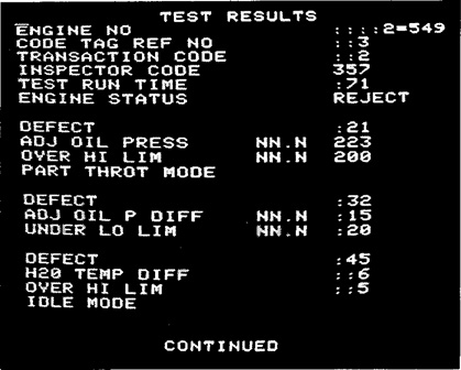
One of the testing stations is illustrated in Figure 19.9. Each station is equipped to supply the required connections for fuel, coolant, electrical ignition, and exhaust. The engines are automatically started and gages indicate the operating characteristics, such as coolant temperature, pressure, and manifold vacuum. The test stations are each interfaced to a programmable controller (refer to Chapter 3) which is connected to a CRT and keyboard console. Figure 19.10 shows the results of an engine testing sequence as they would be displayed on the CRT. The programmable controller cycles the engine through its test sequence by making throttle adjustments to control engine speed versus time.
The system is equipped with several sensors which check engine test results and display them on the CRT. In the event that the measured test parameters do not fall within the limits programmed into the PC for that model, the engine is rejected and is routed to one of four minor repair stations on the loop. These stations are manually operated and are used to make minor repairs and adjustments to the engine. The engine is than retested in the repair station automatically by identical equipment and with the same test sequence.
A foreman’s console is interfaced with all 48 test and repair stations, and display lights which indicate what is happening at each station. The system is designed to be interfaced to a central computer which maintains records of each engine and prepares statistical reports covering the tests. The system operates at a rate of 320 engines per hour, with each test loop operating at 160 units per hour. This amounts to an average testing and handling time of 7.5 min per engine on each test station.
Figure 19.9One test station in system of Example 19.1. (Courtesy of Scans Associates, Inc.)

Figure 19.10 CRT display of engine test results from Example 19.1. (Courtesy of Scans Associates, Inc.)
19.8 Integration of Caqc With CAD/CAM
Although many important benefits result from the use of computer-aided quality control, additional benefits can be obtained by integrating CAQC with CAD/CAM. Throughout the book we have emphasized the merits of an integrated CAD/CAM data base because of the need for both design and manufacturing to use the same basic information about the product. The design department creates the product definition and the manufacturing department makes use of and supplements this definition to develop the manufacturing plan. It is important to add the QC connection to the CAD/CAM framework. The quality control department must use the same CAD/CAM data base to perform its function. Indeed, quality was defined earlier in this chapter as the degree to which a product or its components conform to the standards specified by the designer. These standards are all contained in the CAD/CAM data base, available for QC to use.
One way in which the data base can be used is to develop the NC programs to operate the tape-controlled or computer-controlled coordinate measuring machines. These programs can be generated automatically or interactively by the same methods described in Section 8.8. These programs would then be downloaded to the CMM through a DNC link from the central computer to the controller unit for the CMM. The same sort of downloading process is possible for some of the noncontact inspection methods discussed earlier.
Another way in which a common data base is helpful to QC is when engineering changes are made to the product. Of course, engineering changes are liable to have an influence on inspection and testing. It is helpful for any changes to be recorded in a common data file for all departments, including QC, to use.
Finally, another area where CAD/CAM benefits the QC function is in computer production monitoring. The types of production records that are generated during computer monitoring are sometimes useful to the quality control department in tracing the cause of poor quality in a particular production lot.
References
[1] BALLARD, D. H., AND BROWN, C. M., Computer Vision, Prentice-Hall, Inc., Engle-wood Cliffs, N.J., 1982.
[2] CHASE, R. B., AND AQUILANO, N. J., Production and Operations Management, 3rd, Richard D. Irwin, Inc., Homewood, 111., 1981, Chapter 10.
[3] CHIN, R. T., “Automated Visual Inspection Techniques and Application: A Bibliography,” Pattern Recognition, Vol. 15, No. 4, 1982, pp. 343–357.
[4] “Giving Machines Vision,” Quality Progress, May, 1982, pp. 40-41.
[5] HARRINGTON, J., JR., Computer-Integrated Manufacturing, Industrial Press, Inc., New York, 1973, Chapter 9.
[6] HILDRETH, E. C., “Edge Detection for Computer Vision Systems,” Mechanical Engineering, August, 1982, pp. 48–53.
[7] HUGHES, T., “Winning with Better Quality: Bull’s Eye for Digital Inspectors,” Production Engineering, July, 1982, pp. 38–44.
[8] “Laser-Based Automatic Inspection Systems,” Quality Progress, December, 1981, pp. 26–27.
[9] Monks, J. G., Operations Management, McGraw-Hill Book Company, New York, 1977, Chapter 10.
[10] PUMA, M., “Quality Technology in a Changing Manufacturing Environment,” Quality Progress, August, 1980, pp. 16–19.
[11] SCHAFFER, G., “A New Look at Inspection,” Special Report 714, American Machinist, August, 1979, pp. 103–126.
[12] STAUFFER, R. N., “Inspection Makes Its Mark,” Manufacturing Engineering, August, 1980, pp. 168–172.
[13] ZUECH, N., Personal correspondence dated November 1, 1982.