Chapter 20
Computer-Integrated Manufacturing Systems
20.1 Introduction
In the discrete product manufacturing industries, the most automated form of production is the computer-integrated manufacturing system. A variety of other names have been given to these systems, including flexible manufacturing system (FMS), variable mission manufacturing (VMM), and computerized manufacturing system. The different titles all refer to a production system which consists of a group of NC machines connected together by an automated materials handling system and operating under computer control.
Computer-integrated manufacturing systems (CIMS) incorporate many of the individual CAD/CAM technologies and concepts which we have discussed throughout this book. These include:
Computer numerical control (CNC)
Direct numerical control (DNC)
Computer process control
Computer-integrated production management
Automated inspection methods Industrial robotics
Each CIMS is designed to meet the particular production requirements of the user company. Accordingly, there are differences among the designs of these systems. For example, many of the current CIMS installations do not include robots. The use of industrial robots as a component in these manufacturing systems is a somewhat recent approach.
Computer-integrated manufacturing systems are designed to fill the gap between high-production transfer lines and low-production NC machines. The relative position of the CIMS concept is illustrated in Figure 20.1. Transfer lines are very efficient when producing parts in large volumes at high output rates. The limitation on this mode of production is that the parts must be identical. These highly mechanized lines are inflexible and cannot tolerate variations in part design. A changeover in part design requires the line to be shut down and retooled. If the design changes are extensive, the line may be rendered obsolete. On the other hand, stand-alone NC machines are ideally suited for variations in workpart configuration. Numerically controlled machine tools are appropriate for job shop and small batch manufacturing because they can be conveniently reprogrammed to deal with product changeovers and part design changes. In terms of manufacturing efficiency and productivity, a gap exists between the high-production-rate transfer machines and the highly flexible NC machines. This gap includes parts produced in midrange volumes. These parts are of fairly complex geometry, and the production equipment must be flexible enough to handle a variety of part designs. Transfer lines are not suited to this application because they are inflexible. NC machines are not suited to this application because their production rates are too slow. The solution to this midvolume production problem is the computer-integrated manufacturing system.

Figure 20.1 General application guidelines for the computer-integrated manufacturing system.
In this chapter we describe the types and components of computer-integrated manufacturing systems, as well as their application benefits.
20.2 Types Of Manufacturing Systems
The middle range in Figure 20.1, covering the medium part variety and medium production volume, can be further divided into finer categories. These categories represent different levels of compromise between the objective of flexibility versus production capacity. Kearney ' Trecker Corporation defines three types of manufacturing systems to satisfy the variety of processing needs within this middle range [9,12]. They are:
1. Special manufacturing system
2. Manufacturing cell
3. Flexible manufacturing system (FMS)
Figure 20.2 illustrates the general application guidelines of each of the three types.
The special manufacturing system is the least flexible computer-integrated manufacturing system. It is designed to produce a very limited number of different parts (perhaps two to eight) in the same manufacturing family. The annual production rate per part would typically lie between 1500 and 15,000 pieces. The configuration of the special system would be similar to the high-production transfer line. The variety of processes would be limited, and specialized machine tools would not be uncommon.
Figure 20.2 Application guidelines for the three types of computer-integrated manufacturing systems.
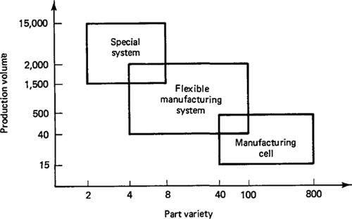
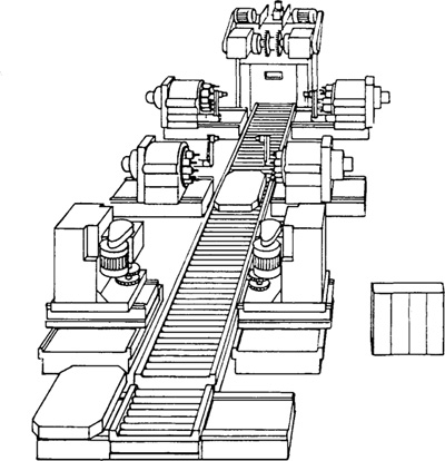
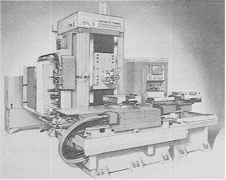
Figure 20.3 Special manufacturing system. (Reprinted from Ref. [9].)
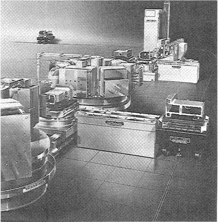
At the opposite end of the midvolume range is the manufacturing cell. It is the most flexible but generally has the lowest production rate of the three types. The number of different parts manufactured in the cell might be between 40 and 800 and annual production levels for these parts would be between 15 and 500.
Figures 20.3 and 20.4 illustrates the special system and the manufacturing cell, respectively. The highly integrated and in-line flow is evident in the workpart handling system of Figure 20.3. As pictured in Figure 20.4, the manufacturing cell might consist of several separate NC machines without an interconnecting materials handling system.
The flexible manufacturing system covers a wide middle territory within the midvolume, midvariety production range. A typical FMS will be used to process several part families, with 4 to 100 different part numbers being the usual case. Production rates per part would vary between 40 and 2000 per year. Figure 20.5 illustrates a representative layout for a flexible manufacturing system.
Workparts are loaded and unloaded at a central location in the FMS. Pallets are used to transfer workparts between machines. Once a part is loaded onto the handling system it is automatically routed to the particular workstations required in its processing. For each different workpart type, the routing may be different, and
Figure 20.4Manufacturing cell. (Reprinted from Ref. [9].)

the operations and tooling required at each workstation will also differ. The coordination and control of the parts handling and processing activities is accomplished under command of the computer. One or more computers can be used to control a single FMS. The computer system is used to control the machine tools and materials handling system, to monitor the performance of the system, and to schedule production. We cover these computer functions in more detail in Section 20.5.
Human labor is required to operate the CIMS. Among the functions performed are loading and unloading of workparts, changing tools, tool setting, and programming the computer system. Section 20.6 dicusses these human activities related to the operation of these manufacturing sytems.
A computer-integrated manufacturing system consists of the following basic components:
1. Machine tools and related equipment
2. Materials handling system
3. Computer system
4. Human labor
We discuss each of these components in the following four sections. The comments will be most applicable to the FMS, which should be considered as the generic
Figure 20.5Sample FMS layout. (Reprinted from Ref. [10].)
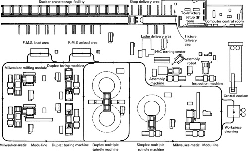
computer-integrated manufacturing system. However, the components and operation of the special system and the manufacturing cell are generally similar to those of the FMS.
20.3 Machine Tools And Related Equipment
The machine tools and other equipment that comprise a computer-integrated manufacturing system include the following:
Standard CNC machine tools
Special-purpose machine tools
Tooling for these machines
Inspection stations or special inspection probes used with the machine tools
Some of the standard NC machines used as FMS components are shown in Figures 20.6 and 20.7.
The selection of the particular machines that make up a CIMS depend on the processing requirements to be accomplished by the system. These processing needs also influence the design of the parts handling system. Some of the factors that define the processing requirements are the following:
Figure 20.6 Duplex multiple spindle head indexer used as module on CIMS. (Courtesy of Kearney ' Trecker Corp.)

Figure 20.7 Machining center module used on CIMS. (Courtesy of Kearney ' Trecker Corp.)
1. Part size. The size of the workparts to be processed on the CIMS will influence the size and construction of the machines. Larger parts require larger machines.
2. Part shape. Machined workparts usually divide themselves naturally into two types according to shape: round and prismatic. Round parts, such as gears, disks, shafts, requiring turning and boring operations. Prismatic workparts, which are cube-shaped and nonrotational, require milling and drilling operations.
3. Part variety. If the part variety is limited, the machine tools would be more specialized for higher production. The CIMS would be designed as a special system. If a wide variety of parts are to be processed, standard machine tools which are more versatile would be selected.
4. Product life cycle. The influence of product life cycle is similar to that of part variety. If the product life is relatively long, the CIMS can include more specialized and less flexible machine tools.
5. Definition of future parts. Another factor that affects the versatility of the CIMS is the level of knowledge about parts which are to be processed. We can distinguish two cases. The first case is where the manufacturing system is designed to process a family of parts that are completely known in advance. An example of this case is the dedicated manufacturing system for machining components of the XM-1 tank. The range of components is precisley known at the time of CIMS design and the system can be configured to meet these specific needs. The other case is where the future parts are not known in advance. New part designs must be accommodated by the system; therefore, its machine tools must possess a significant degree of flexibility.
6. Operations other than machining. Most computer-integrated manufacturing systems are designed for machining exclusively. In some cases the processing requirements include other operations, such as assembly or inspection.
20.4 Material Handling System
The material handling system in a CIMS must be designed to serve two functions. The first function is to move workparts between machines. The second function is to orient and locate the workparts for processing at the machines. These two functions are often accomplished by means of two different but connected materials handling systems. We shall refer to them as the primary handling system and the secondary handling system.
The primary work handling system is used to move parts between machine tools in the CIMS. The requirements usually placed on the primary material handling system are:
It must be compatible with computer control.
It must provide random, independent movement of palletized workparts
between machine tools in the system.
It must permit temporary storage or banking of workparts.
It should allow access to the machine tools for maintenance, tool changing and so on.
It must interface with the secondary work handling system.
The term “random, independent movement of parts” means that the parts must be able to flow from any one station (machine tool) to any other station. This requirement is not always necessary in the case of the special manufacturing system, which may involve an in-line flow of parts based on a fixed processing sequence.
The secondary parts handling system must present parts to the individual machine tools in the CIMS. The secondary system generally consists of one transport mechanism for each machine. The specifications placed on the secondary materials handling system are:
It must interface with the primary handling system. Parts must be transferred automatically between the primary system and the secondary system.
It must be compatible with computer control.
It must permit temporary storage of workparts.
It must provide for parts orientation and location at each workstation for processing.
It should allow access to the machine tool for maintenance, tool changing, and so on.
An illustration of the primary and secondary work handling systems is found in Kearney ' Tracker’s FMS concept shown in Figure 20.8. The primary work handling system is an under-the-floor towline system which pulls a series of carts between the different workstations. The carts have four wheels which roll on the floor surface. Slots in the floor define the permissible pathways for the carts. These paths may branch and merge in a manner similar to that depicted in Figure 20.5. The layout of the pathways depend on the design of the FMS. Guide pins at the front and back of the carts engage the slot in the floor to follow the correct path. The front guide pin engages a moving chain in the slot, which propels the cart.
The secondary work handling system is the shuttle system at each machine. The shuttles are designed to transfer palletized parts to and from the towline carts, and to move them onto and off the machine tool table for accurate registration with the curling tools. If the processing cycle at the workstation is relatively short, the
Figure 20.8 In-floor towline cart system combined with pallet shuttle system on a flexible manufacturing system. (Courtesy of Kearney ' Trecker Corp.)
shuttle system may also be required to maintain an inventory of parts ready for machining. Both the towline cart and shuttle system are shown in Figure 20.8.
The use of both a primary and a secondary work handling system is not always required to satisfy the material handling objectives of a CIMS. In some cases, the objectives can be satisfied with one work handling system. In the special system illustrated in Figure 20.3, the fact that all parts are processed in the same sequence means that the same roller conveyor system can fully accomplish the inline flow of parts needed for this manufacturing system.
A relatively recent innovation in the design of flexible manufacturing systems involves the use of industrial robots to perform a portion of the parts handling chore. Figure 20.9 shows the layout for a robotic manufacturing cell. The geometry of the workparts to be processed on the CIMS has a big influence on the type of work handling system. Round workparts have been found to be ideal candidates for handling by industrial robots. The robot is physically located in the center of a group of machine tools and transfers parts from one machine to the next in an independent,
Figure 20.9 Layout of manufacturing cell with robot used for parts transfer between machines. (Reprinted from Ref. [14].)
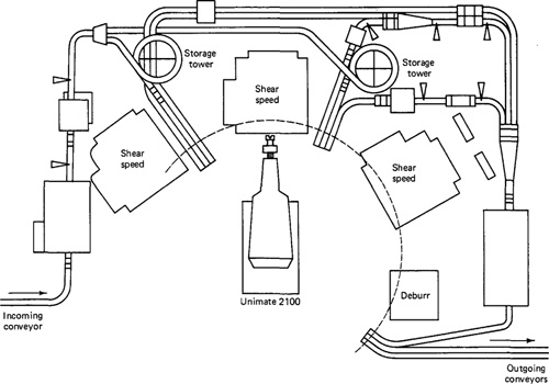
random fashion depending on processing requirements for each part. It has been estimated that 75% of all rotational parts can be accommodated in a machining cell which uses a robot as the handling mechanism [8]. Most round parts are within the lift capacities of the common commercially available robots. The design problem is to develop a gripper device that is suited to the variety of parts handled in the cell.
Prismatic parts which are processed by machining are usually heavier and larger. Robots cannot generally be used to transport these parts within the manufacturing system. The handling problem is typically solved by mounting the part on a pallet fixture and designing a materials handling system (primary system and secondary system) which will transport the standard-size pallet as required. Typical solutions include the following types of materials handling systems:
Towline cart combined with shuttle system as illustrated in Figure 20.8, in a layout similar to that of Figure 20.5.
Roller conveyor system. Figure 20.3 illustrates this form of handling system.
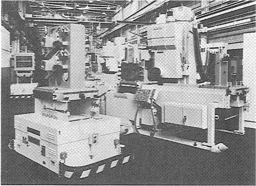
Guided vehicle combined with shuttle system. A wire-guided cart is illustrated in Figure 20.10.
A means of coordinating the activities of the materials handling system with those of the machine tools in the CIMS must be achieved. This is done by the computer control system.
Figure 20.10 Wire-guided cart used in variable mission manufacturing system. CNC machining center in background. (Courtesy of Cincinnati Milacron.)
20.5 Computer Control System
This section describes how the digital computer system is used to manage the operation of a complex manufacturing system. We discuss the various functions performed by the computer, the data files needed to carry out these functions, and the various types of reports that the computer can be programmed to prepare.
Functions of the computer in a CIMS
The functions accomplished by the computer control system can be divided into eight categories. The following descriptions apply best to the case of the flexible manufacturing system. To a slightly lesser extent, they also apply to the special system and the manufacturing cell.
1. Machine control. This is usually accomplished by computer numerical control (CNC). The advantage of CNC is that it can be conveniently interfaced with the other elements of the computer control system.
2. Direct numerical control (DNC). Most computer-integrated manufacturing systems operate under DNC. In some of the special systems which are dedicated to a limited part variety, CNC may be a sufficient control method for the system. The purpose of direct numerical control is to perform the usual DNC functions, including NC part program storage, distribution of programs to the individual machines in the system, postprocessing, and so on.
3. Production control. This function includes decisions on part mix and rate of input of the various parts onto the system. These decisions are based on data entered into the computer, such as desired production rate per day for the various parts, numbers of raw workparts available, and number of available pallets. The computer performs its production control function by routing a pallet to the load/unload area and providing instructions to the operator to load the desired raw part. A data entry unit(DEU) is located in the load/unload area for communication between the operators and the computer.
4. Traffic control. This term refers to the regulation of the primary work-piece transport system which moves parts between workstations. This control can be accomplished by dividing the transport system into zones. A zone is a section of the primary transport system (towline chain, conveyer, etc.) which is individually controlled by the computer. By allowing only one cart or pallet to be in a zone, the movement of each individual workpart is controlled. The traffic controller operates the switches at branches and merging points, stops workparts at machine tool loading points, and moves parts to operator load/unload stations.
5. Shuttle control. This is concerned with the regulation of the secondary part handling systems at each machine tool. Each shuttle system must be coordinated with the primary handling system, and it must also be synchronized with the operations of the machine tool it serves.
In cases where there is only one parts handling system (rather than a primary and secondary handling system) the functions of traffic control and shuttle control may be combined. This would be the case in some of the special systems and certain robotic work cells.
6. Work handling system monitoring. The computer must monitor the status of each cart and/or pallet in the primary and secondary handling systems as well as the status of each of the various workpart types in the system.
7. Tool control. Monitoring and control of cutting tool status is an important feature of the computer system. There are two aspects to tool control: accounting for the location of each tool in the CIMs and tool-life monitoring.
The first aspect of tool control involves keeping track of the tools at each station in the system. If one or more tools required in the processing of a particular workpart are not present at the workstation specified in the part’s routing, the computer control system will not deliver the part to that station. Instead, it will determine an alternative machine to which the part can be routed, or it will temporarily “float” the part in the handling system. In the second case, the operator is notified via the data entry unit what tools are required in which workstation. The operator then manually loads the tools and notifies the computer accordingly. Any type of tool transaction (e.g., removal, replacement, addition) must be entered into the computer to maintain effective tool control.
The second aspect of tool control is tool-life monitoring. A tool life is specified to the computer for each cutting tool in the CIMS. Then a file is kept on the machining time usage of each tool. When the cumulative machining time reaches the life for a given tool, the operator is notified that a replacement is required.
8. System performance monitoring and reporting. The system computer can be programmed to generate various reports desired by management on system performance. The types of reports are discussed later in this section.
These computer functions can be accomplished by any of several different computer configurations. One computer can be used for all components of the CIMS, or several different computers can be used. Up to three levels are practical in a given manufacturing system. CNC would be used for control of each individual machine tool. DNC would be appropriate for distribution of part programs from a central control room to the machines. A third level would concern itself with production control, the operation of the work handling system, tool control, and generation of management reports.
CIMS data files
To control the operation of the manufacturing system, the computer relies on data contained in files. The principal data files required are of the following six types:
1. Part program file. The part program for each workpart processed on the system is maintained in this file. For any given workpart, a separate program is required for each station that performs operations on the part.
2. Routing file. This file contains the list of workstations through which each workpart must be processed. It also contains alternate routings for the parts. If a machine in the primary routing is down for repairs or there is a large backlog of work waiting for the machine, the computer will select an alternate routing for the part to follow.
In the special system, where the routings would be identical or similar and the parts proceed through the system in an in-line flow, the importance of the routing file is substantially reduced.
3. Part production file. A file of production parameters is maintained for each workpart. It contains data relative to production rates for the various machines in the routing, allowances for in-process inventory, inspections required, and so on. These data are used for production control purposes.
4. Pallet reference file. A given pallet may be fixtured only for certain parts. The pallet reference file is used to maintain a record of the parts that each pallet can accept. Each pallet in the CIMS is uniquely identified and referenced in this file.
5. Station tool file. A file is kept for each workstation, identifying the codes of the cutting tools stored at that station. This file is used for tool control purposes.
6. Tool-life file. This data file keeps the tool-life value for each cutting tool in the system. The cumulative machining time of each tool is compared with its life value so that a replacement can be made before complete failure occurs.
System reports
The data collected during monitoring can be summarized for preparation of performance reports. These reports are tailored to the particular needs and desires of management. The following categories are typical:
1. Utilization reports. These are reports that summarize the utilization of individual workstations as well as overall average utilization for the system.
2. Production reports. Management is interested in the daily and weekly quantities of parts produced from the CIMS. This information is provided in the form of production reports which list the required schedule together with actual production completions. One possible format for the production report is illustrated in Figure 20.11.
3 Status reports. Line supervision can call for a report on the current status of the system at any time. A status report can be considered an instantaneous “snapshot” of the present condition of the CIMS. Of interest to supervision would be status data on workparts, machine utilization, pallets, and other system operating parameters.
4. Tool reports. These reports relate to various aspects of tool control. Reported data might include a listing of missing tools at each workstation. Also, a tool-life status report can be prepared at the start of each shift, similar to the one
Figure 20.11 Production shift report, indicating CIMS performance. (Reprinted from Ref.[10].)
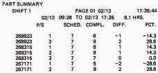
Figure 20.12 Tool status report for one machine tool in a CIMS. (Reprinted from Ref. [10].)
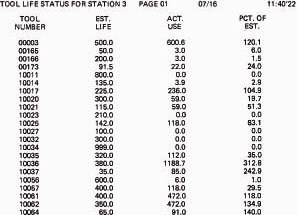
illustrated in Figure 20.12. This listing shows that several of the tools have been used well beyond their anticipated lives and are in need of replacement.
20.6 Human Labor In The Manufacturing System
The computer-integrated manufacturing system is a highly automated production facility. However, human resources are required to operate the system. In the majority of CIMS installations, the individual machines are operated under CNC or DNC control (or a combination of these). The machines are not manually operated except in certain special operations, such as assembly. Personnel are required principally to manage, maintain, and service the CIMS. Paprocki [12] lists the following personnel requirements for a computer-integrated manufacturing system:
1. System manager. This person has overall responsibility for the operation of the CIMS. The functions include production planning, responding to deviations and exceptions to normal operations, and supervision of the other human resources which support the system.
2. Electrical technician. This person is often a member of the plant’s electrical maintenance crew. Duties performed include maintenance and repair services on the electrical components of the machine tools and materials handling system.
3. Mechanical/hydraulic technician. Again, this person is likely to be a regular member of the plant maintenance department. Technical services consist of maintenance and repair of the mechanical and hydraulic components of the CIMS.
4. Tool setter. The tool setter is responsible for the tooling inventory and making the tools ready for production.
5. Fixture setup and lead man. This person is responsible for setting up the fixtures, pallets, and tools for the system.
6. Load/unload man. This person is responsible for loading raw workparts and unloading finished parts. This is typically done according to instructions and schedules generated by the computer. The load/unload area is at a convenient central location in the manufacturing system.
7. Rover operator. The duties of the rover operator include reacting to unscheduled machine stops, identifying broken tools or tools in need of immediate replacement, tool adjustments, and so forth. This person may also be responsible for certain manual production tasks or inspection operations.
Although each of these functions must be accomplished, this does not necessarily mean that seven people are required full time to operate the CIMS. The electrical technician and the mechanical/hydraulic technician are required on an on-call basis. In most companies, these workers would report to the plant maintenance department. In the startup of a new manufacturing system they might be required full time to solve the many problems which are typically associated with a new installation of complex equipment. Under normal operation, these technicians would devote only part of their time to the CIMS.
The remaining five functions might be combined to some extent to reduce the actual number of people required. The duties of the tool setter, lead man, and rover operator might be shared by two persons rather than three. The amount of human resources needed to operate the manufacturing system will depend to a large degree on its size, number of processing machines, and level of sophistication and automation.
In addition to these seven operational functions, NC part programmers, computer programmers, and related support staff are required to prepare the programs by which the computer system will control production and monitor performance.
20.7 CIMS Benefits
Computer-integrated manufacturing systems are intended for midvolume, mid-variety production situations, as illustrated in Figure 20.1. Competing methods of production include group technology manufacturing cells1 and conventional process layout shops which utilize stand-alone NC machines or special non-NC machines. When applied in the proper circumstances, a CIMS offers the following benefits:
1 In many respects, a CIMS is a group technology manufacturing cell.
1. Increased machine utilization. Most NC machines may operate at about 50% utilization or less. Because of minimum setup times, efficient workpart handling, simultaneous workpart processing, and other features, the utilization of a flexible manufacturing system may run as high as 85%. Downtime on a computer-integrated manufacturing system typically results from problems similar to those that plague a stand-alone NC machine. These include tooling problems, electrical and computer problems, and mechanical and hydraulic problems. Other reasons for downtime on a CIMS include scheduled maintenance and tool changeovers.
2. Reduced direct and indirect labor. Given the higher utilization and greater productivity of a CIMS, the cost of direct and indirect labor per unit of production is lower for this form of production than for the alternatives. In the operation of a CIMS, the labor allocation may be three or four workers for 6 to 10 machine tools. In the typical operation of many stand-alone NC machines, one operator is used for each machine. Accordingly, the ratio of direct labor cost to machines is reduced for the CIMS. Indirect labor for the CIMS is reduced compared to job shop operation through automated material handling, as opposed to manual parts handling in conventional batch production.
3. Reduced manufacturing lead time. Most workparts require processing in batches through several different work centers. There is setup time and waiting time at each of the work centers. With computerized manufacturing systems, the nonoperation time is drastically reduced between successive workstations on the line. Also, setup time is minimized in the CIMS operation. The setup for a traditional production machine consists of two main elements: tooling setup and workpart setup. Tooling setup means collecting the required tools from the tool crib and setting them in the machine. Workpart setup involves adjusting the workholding fixture, getting the raw materials ready, and so on. The tooling for a CIMS is preset off-line. The tool setup for a particular workstation consists of loading the preset tools required for the job into the tool drum at that station. Each tool drum may be capable of holding up to 60 or more cutting tools. The workpart setup is performed external to the CIMS. Since pallets are used to transport parts from station to station, the setup consists of adapting the pallet to the particular part for holding it. This setup is accomplished in the load/unload area before the part and pallet are launched onto the system. Fixtures are designed that can adapt to various part configurations within a part family. Several different adaptable fixtures may be required to handle the various part families. The parts are clamped in place onto the fixture, and the fixture is attached to the pallet. The CIMS has a large number of these pallets (the pallets may outnumber the workstations by 5 to 1), so some pallets can be off the system being loaded or unloaded, while other pallets are being used on the system. These features of the manufacturing system allow the processing lead time to be significantly reduced.
4. Lower in-process inventory. The float of workparts in process on a CIMS is significantly below the corresponding level for conventional batch manufacturing. In-process inventory is related closely to production lead time. Because the parts spend a relatively short time in the system, the number of parts being processed is low.
5. Scheduling flexibility. Random launching of workparts onto the system means that any workpiece handled by the CIMS can be introduced without downtime for setup. When the part is launched onto the system, the computer system routes it to the proper machines. The only limitation is that the workstations must be equipped in advance with the tooling required to process the particular workpart. This method of operation gives the system considerable flexibility to deal with changes in the production schedule.
It should be noted that the three types of CIMS vary in their scheduling flexibility. The special system is the least flexible and the manufacturing cell is the most flexible. In the case of the flexible manufacturing system, it is desirable to maintain a mixture of parts on the system. The FMS is designed to process various part configurations simultaneously by using its workstations concurrently. If only parts of the same type are launched onto the system, the workstations required for the particular part type will tend to be fully utilized, while other stations will be underutilized. As a result of this consideration, it is desirable to schedule a mix of parts on the FMS.
References
[1] CINCINNATI MILACRON, Concept for Variable Mission Manufacturing Systems (marketing brochure), Cincinnati, Ohio, 1979.
[2] CLNCINNAN MILACRON, Variable Mission Modular Manufacturing Systems (marketing brochure), Cincinnati, Ohio, 1980.
[3] CURTIN, F. T., “Manufacturing Systems Moving Stage Center in Dramatic Search for Better Productivity,” N/C Commline, January/February, 1979, pp. 34–35.
[4] GROOVER, M. P., Automation, Production Systems, and Computer-Aided Manufacturing, Prentice-Hall, Inc., Englewood Cliffs, N.J., 1980, Chapter 19.
[5] HATSCHEK, R. L., “Guided Carts Link Machines into Systems,” American Machinist, August, 1980, pp. 97–100.
[6] HUBER, R. F., “90% Uptime from Unmanned Machining Systems,” Production, June, 1979, pp. 68–73.
[7] HUBER, R. F., “Planning for a Flexible Machining System,” Production, August, 1981, pp. S–67–S–85.
[8] JABLONSKI, J., “Aiming for Flexibility in Manufacturing Systems,” Special Report 720, American Machinist, March, 1980, pp. 167–182.
[9] KEARNEY ' Trecker Corp., K'Ts World of Manufacturing Systems,Milwaukee, Wis., 1980.
[10] KEARNEY ' Trecker Corp., Understanding Manufacturing Systems (a series of technical papers). Vol. I, Milwaukee, Wis.
[11] MATTOX, J. E., “Industrial Robots and Integrated Manufacturing Systems,” N/C Commline, January/February, 1979, pp. 41–45.
[12] PAPROCKI, J. T., “Flexible Manufacturing Systems Automating the Factory,” technical paper presented to the 2nd International Manufacturing Management and Technology Conference, Munich, Germany, June, 1979.
[13] SPROW, E. E., “FMS: On the Launch Pad,” Tooling and Production, January, 1982, pp. 74–80.
[14] UNIMATION, INC., Unimate Industrial Robot System Planbook,Danbury, Conn.