CHAPTER 8. Network Switches
SOME OF THE MAIN TOPICS IN THIS CHAPTER ARE
Switch Troubleshooting and Management 135
Ethernet switches provide a single-device replacement for two older Ethernet devices:
![]() A switch connects multiple network segments to each other, just as a hub does.
A switch connects multiple network segments to each other, just as a hub does.
![]() A switch manages traffic between systems to prevent collisions, just as a bridge does.
A switch manages traffic between systems to prevent collisions, just as a bridge does.
Switches also provide several benefits compared to hubs and bridges. Notably, most switches support full-duplex operation, enabling faster network performance. They also provide full bandwidth to each device, rather than subdividing bandwidth among ports as hubs do.
For these reasons, switches have replaced hubs in all but the oldest networks. This chapter explains how switches work, the types of switch hardware, and how to manage and troubleshoot switches. Without switches, Ethernet networks would have been maxed out a few years ago with 100BASE-T (Fast Ethernet) hub solutions.
Note
Routers can be used to extend a network. However, the difference between a network router and a pure LAN switch is significant. Routers are used to direct network frames to the correct network or subnet on which the destination host resides, or to another router that may know of the destination network that lies in the path to the destination network.
Although routers can be used within large networked environments to segregate physical network segments, they are generally considered to be WAN devices—used to connect a LAN to the Internet or a larger private intranet. Switches, in the form most used today, are used to get past the limitations imposed by traditional LAN technologies, including the bus topology, the hub, and the bridge. However, at the end of this chapter, you’ll see how switching technology has also moved up the ladder into the WAN market.
A major difference between routers and LAN switches is that a router makes decisions based on the network portion of the IP address, whereas switches work at a lower level and make decisions based on the Media Access Control (MAC) address burned into the network card by the manufacturer. Because the MAC address space is random, and the IP address space is hierarchical, LAN switches would need a routing table so large that it would not be possible to store every MAC address for every computer in the world today. Yet routers can use the network portion of an IP address to send a packet on its way because of the very nature of the hierarchical address space (network address/client address) provided by IP. LAN switches can work quickly because they only need to look at the MAC address, which is always located in the same part of the Ethernet frame that carries the IP packet as its payload.
Note that wired or wireless routers found in many SOHO networks actually contain Ethernet switches as well as routers. In essence, these devices integrate formerly-separate components into a single device.
How Switches Work
When hubs were in widespread use your Ethernet LAN was limited to the number of workstations you could attach to any particular LAN segment or hub. The limitation was based on the total available bandwidth, which usually is 10Mbps or 100Mbps using older hub technology. Because the broadcast domain, which is to say the group of network devices—including workstations, servers, and hubs—that are capable of broadcasting a packet to any other device on the network, even if you follow the topological rules for creating a traditional Ethernet LAN, it won’t matter how many computers you are able to connect to the LAN if network traffic becomes a problem. This happened frequently in networks with several high-end servers or workstations that made heavy demands on the network.
Hubs do not diminish the broadcast domain, because all devices connected to the hub must still use the Ethernet CSMA/CD method to gain access to the network media.
Note
Because early Ethernet networks used a shared network media, each node on the network had to contend for access to the network. The mechanism used to get access to the shared media is called Collision Sense Multiple Access/Collision Detect (CSMA/CD). A computer attempting to transmit data on the shared media first listens to ensure that no one else is already transmitting (collision sense). If the line is free, the computer can begin to transmit data. Yet, because the length of the cables and/or hubs that make up the shared media can be lengthy, it’s possible that another node may sense the media to be available at the same time, and start transmitting (multiple access). When this happens, a collision occurs. The collision can be detected because it generates a higher voltage on the wire. The collision domain consists of all those computers (or other devices) that must compete in the same shared media, be it a single cable or many cables interconnected by hubs. Switches have solved this problem in modern Ethernet equipment.
On the other hand, a bridge is used to connect two network segments and reduce the broadcast domain by passing network traffic from one segment to another based on a table that the bridge uses to determine which computers are located on which physical segments. This all led to the development of switches. Consider a switch to be a device that uses circuitry to create multiple bridges between the ports it provides.
The solution to the problem outlined here is to limit the broadcast domain without the need for dedicated network bridges, which aren’t sufficient for the needs of today’s high-speed networks and applications, which must often support use of streaming audio and video alongside more traditional network traffic, such as file and print services.
A switch is a cross between a bridge and a hub. You can think of a switch as several bridges, centralized in a single device like a hub, with added monitoring and management capabilities. Switches centralize wiring and cut down on unnecessary broadcasts on the LAN by switching network packets from an incoming port to the outgoing port that will get the packet to its destination. A switch thus limits the broadcast domain to just two devices: the switch port and the network adapter card on a computer. This eliminates the need for other workstations attached to the switch to examine each packet broadcast on the network. The other workstations never see the packet to begin with. The outgoing port may be connected to the destination of the frame, or it may be connected to another switch, or perhaps a router, that will forward it until it reaches the destination computer.
Switches and bridges aren’t that different. They perform just about the same function. However, early bridges usually had only two ports to connect two LAN segments and, thus, divide the broadcast domain in half. As technology developed rapidly in the 1990s, it became possible to create multiport bridges you could use to attach multiple LAN segments. Switches today can be used to connect multiple LAN segments or to connect individual workstations or servers to the network.
So although the term switch may sound new, it’s just an evolutionary update of an older technique—bridging, combined with the central wiring concentrator function provided by a hub. You can use switches to perform the same functions that were performed earlier using bridges, but switches allow you to connect a lot more computers to your LAN. Switches have been around for many years in the high-end marketplace for large LANs and have more recently replaced smaller SOHO hubs at the low end. Today traditional hubs are not at all common since there is almost no cost benefit to purchasing one instead of a switch. For larger networks, larger rack-mounted switches have also come down in price. This is due to the fact that there are a lot of manufacturers (for both markets) and switches are now commonplace in high-end networks.
Note
One important distinction between earlier bridges and modern switches needs to be made. Bridges were initially designed to connect two or more LAN segments together. Each LAN segment could have a single computer or multiple computers connected to it. Bridges generally were used to segment the broadcast domain by connecting LAN segments that had multiple computers attached. Switches, however, are used to connect a single computer to a switch port, which can switch the data out another switch port to another target computer, or another switch that can deliver the packet to the target device.
Segmenting the Collision Domain
In Chapter 13, “Ethernet: The Universal Standard,” you’ll learn more about the limitations imposed for configuring a network based on the technology used. Each type of Ethernet, from 10BASE-2 to Gigabit and 10Gigabit Ethernet, has its own rules about the number of computers that can be connected, the length of cables, and so on. After you reach the maximum allowed length or number of computers imposed by the particular topological rules, you have to create a new LAN and, usually, connect them with a router. Gigabit and 10Gigabit Ethernet are currently used as part of a network backbone because of their large bandwidth. Yet, as desktop computers continue along their evolutionary line and get faster, and as the same thing happens with application software and data, Gigabit Ethernet is now migrating steadily to the desktop. Many recent computers now incorporate Gigabit Ethernet NICs, and all levels of network hardware vendors, including some in the SOHO space, manufacture Gigabit Ethernet NICs, and switches. Applications that use large amounts of data, such as video editing, can benefit from this large bandwidth to the desktop. A word processor, however, would use only a very small fraction of Gigabit Ethernet!
In Figure 8.1 you can see that a switch is used to connect individual workstations, servers, and other network devices.
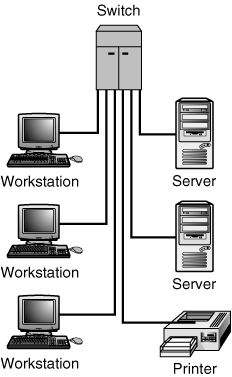
Figure 8.1. You can connect individual computers to a switch port.
The benefits of using a switch should quickly become apparent. The broadcast domain, when using the standard half-duplex Ethernet CSMA/CD technology, is limited to just two devices: the switch port and the computer attached to it. In this standard half-duplex mode, however, collisions still can occur if the switch and the computer attached to it sense that the network media is silent and both attempt to transmit at the same time. This is exactly what happens in a traditional Ethernet LAN when the CSMA/CD mechanism described in Chapter 13 is used. However, with only two devices competing for network access, bandwidth is greatly improved.
If you were to substitute a hub for the switch in Figure 8.1, the network traffic from all the workstations attached to the hub would have to compete for access to the network media. This means that if you were to use a hub, the actual bandwidth available to each workstation would be less than when a switch is used. As more and more workstations on a hub begin to generate large amounts of network traffic, the effective use of the network media begins to lessen as more and more collisions occur. Using a switch solves this problem.
Full-Duplex Ethernet Switches
The switch also makes possible the concept of full-duplex communication over Ethernet. As discussed in the preceding section, in a standard Ethernet implementation, each device must contend with all others that want to use the transmission medium. The CSMA/CD mechanism is used so that only one device successfully ends up talking on the wire at any particular time. The more stations that are added to the collision domain, the lower the total throughput because collisions increase and retransmissions become more frequent.
When a single workstation is connected to a switch, you want to further increase bandwidth by eliminating the collision domain altogether. This is exactly what happens when you use a switch that supports full-duplex communication. In this type of switch, separate wires in the network cable are used for transmitting and receiving. Thus, the switch port can be transmitting frames to the workstation on one set of wires, while the workstation is transmitting frames to the switch port on another wire pair in the cable.
Because there are no competing devices, the switch and the workstation can send and receive from each other at the same time, the result of which is a full-duplex operation. No collisions occur because there is no contention for the wire. Not only can you achieve the actual 10Mbps or 100Mbps throughput capabilities of the wire for each port attached to a full-duplex switch, but you can double those speeds—100Mbps in each direction because each side of the connection can use the full 100Mbps bandwidth. And as Gigabit Ethernet is deployed to the edge of the network, you can expect to see even greater throughput. This will become very important in the next year or two as higher-end PCs and workstations become widely used for large graphics and video applications.
Most network adapter cards, even the very inexpensive ones you can find at a local computer store, support both 10Mbps and 100Mbps full-duplex communications. You can find a generic store brand usually for under $15. If you still have older NICs used in your network, at this price, it only makes sense to throw out those older cards (which probably cost you a lot more!) and upgrade to a newer card.
That said, most switches, both inexpensive SOHO devices and those intended for use in an enterprise network, still support both 10 and 100Mbps. The main reason why you will see some network adapters priced at higher levels ($50–$100) is that they offer advanced features, which may be useful to your environment. And, as you learned in Chapter 7, “Network Interface Cards,” there are other features that become especially useful when used in enterprise networks, such as Wake on LAN and Preboot Execution Environment (PXE) Boot.
Note
Full-duplex communications are the key to faster Ethernet technologies. After you pass the 100BASE-T speed of 100Mbps, the packet size and round-trip timing required for Ethernet networks just doesn’t scale very well. Newer technologies, such as Gigabit Ethernet and 10 Gigabit Ethernet, depend on this full-duplex capability and the removal of the CSMA/CD media access control mechanism to achieve their speeds.
You can increase the availability of the server to its clients, and incur only the expense of a new network card for the server, by replacing the network card on the server with a full-duplex card and plugging it into a port on the switch that supports full-duplex operations. You can increase the response time of the PC or workstation by doing the same.
To make upgrading to a 100Mbps switch easier, virtually all products provide the capability of dual-speed ports. This is similar to the dual-speed 10/100Mpbs network cards. Thus you can continue to use older network cards with a new switch until your budget allows for upgrading the cards installed in individual workstations. Just about every switch on the market today can autosense the network speed of the workstation attached to the port. However, some older models require that you manually set the speed, using management software. The best switches support both autosensing and a good management program that can be used to configure ports.
Note
The best laid plans...can often go awry. Even though there are standards organizations and trade associations that set standards for all sorts of network devices, such as network adapter cards, this doesn’t mean that a card (or switch) will always work as expected. This author recently had a problem with several high-end servers (AlphaServers running OpenVMS) that were capable of handling several thousand user connections at any point in time. The servers used autosensing 10/100Mbps full-duplex cards, yet for some reason the throughput was operating in a 10Mbps half-duplex mode. After user complaints, the problem was resolved by manually configuring the switch port to use 100Mbps, full-duplex communications for the particular port. In other words, if you don’t find your expectations met when you install new equipment, check the alternatives.
Using Switches to Create a Collapsed Backbone
Because switches can effectively eliminate the broadcast domain, you also can use them to eliminate the traditional backbone used to connect multiple hubs or other devices. For example, it’s easy to set up a hub or switch in a wiring closet on each floor of a building, and then run a single cable through the floors to connect each hub (as shown in Figure 8.2). This cable is the backbone for the network. However, this does nothing to eliminate the collision domain for all the traffic it receives from the switches or hubs.
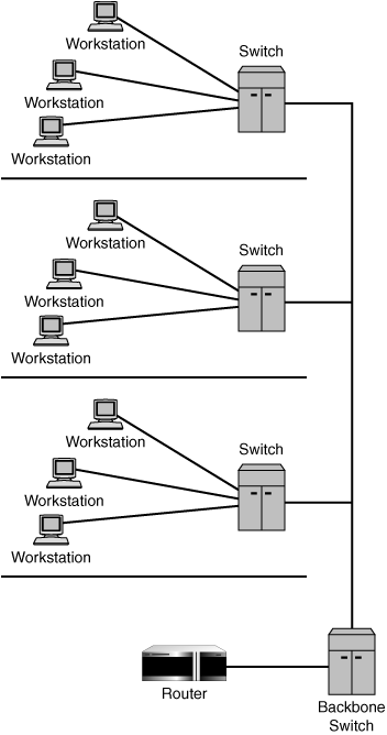
Figure 8.2. A single backbone becomes a bottleneck in a large network.
In Figure 8.2, each workstation that is attached to the switch on its floor easily can exchange data with other workstations that are attached to the same switch. However, if a workstation needs to communicate with a server or another resource that is not directly connected to that switch, the network traffic flows over the backbone that connects the other departmental switches. Again, this isn’t a problem if you have a network in which you can locate important servers closer to the actual clients that use them and prevent traffic from entering the backbone at all.
In today’s environment, however, it’s common to find many business functions centralized in data centers, in large servers, or possibly in clustered servers that manage huge databases. In this type of scenario, it isn’t always easy to move a server closer to the client. And, with the advent of email and other Web-based applications, it’s more likely that the old 80/20 rule—80% of network traffic stays within the local LAN, whereas only 20% is destined for other locations—has been turned around. Now most clients need to exchange only a small amount of data with local computers, sending the 80% figure to the larger network. As newer technologies, such as systems running Windows 2003 Server, begin to distribute components of applications among multiple computers, this problem becomes a more important consideration when planning a network. With the centralization of larger servers, most likely you’ll see this paradigm in all but the smallest networks in the future.
In Figure 8.3, switches are cascaded so that the switch can become a network backbone-in-a-box. Each switch in the building is connected to a central switch that serves as the backbone, again limiting or eliminating the collision domain, depending on whether full- or half-duplex switch ports are used.

Figure 8.3. A central switch can serve as a collapsed backbone to concentrate departmental switches.
Of course, in this example, the switches appear on each floor, but you could just as easily attach switches at the department level. In Figure 8.3, it’s important to note that, instead of sharing a single backbone network cable as in Figure 8.2, each departmental switch has its own cable to the switch, so the full bandwidth of the network media is available to each switch. The backbone no longer becomes a bottleneck. This does, however, mean that switched connections between devices on one switch with devices on another switch may suffer some minor degradation in bandwidth, but in most cases this problem can be resolved by isolating the computers or servers that need a high-speed link and simply relocating their network connections to different switches to ensure a larger data pipe. If you use Gigabit Ethernet adapters and switches, any loss of bandwidth will not be perceptible.
Switch Hardware Types
It’s not much of a stretch to argue that switches are a network administrator’s dream come true, at least most of the time. But when you decide to incorporate switches, there is something else to consider: Not all switches use the same technology. The importance of this distinction depends on which of these functions of a switch is the most important to you:
![]() Increasing the bandwidth for computers attached to a switch.
Increasing the bandwidth for computers attached to a switch.
![]() Decreasing the possibility that frame errors will be propagated end-to-end in a network link.
Decreasing the possibility that frame errors will be propagated end-to-end in a network link.
Many architectures are used for switching, as described in the following sections, and because of that, many approaches have been and are being tried. Some involve software that makes decisions much like a router and sends frames on their way. Others are hardware-based and can perform much better because no single component, such as a CPU, can be bogged down when too much traffic passes through the switch. Two basic modes of operation can be used by a switch when it forwards a packet out of a selected port: cut-through mode and store-and-forward mode.
Cut-Through Switches
A cut-through switch begins transmitting the incoming frame on the outgoing port after it receives the header information, or about 20 or 30 bytes. All the switch needs to determine on which port to output the frame is the destination address (hardware address), which is determined by the MAC address found in the frame header. The switch continues to receive information and transmit it until the frame has been “switched” from one port to another. The advantage to this mode of operation is speed. As long as nothing else goes wrong, the packet continues on to its destination at a fast pace with little time involved in the switch. The switch is said to be switching at wire speed. That is, the delay introduced by the switching function is so insignificant that to the end workstations, the full bandwidth is available for use.
This method has several disadvantages, however. The switch begins to send the packet out before it knows whether the frame is damaged in any way. If the frame has corrupted data, the switch won’t be able to detect it unless it first receives the entire frame and then computes the CRC (cyclic redundancy check) value stored in the frame check sequence field. If a frame is badly malformed, as when an NIC sends out a frame that is too long, a cut-through switch might think it is a broadcast packet and send it out of all ports, causing unnecessary traffic congestion.
Store-and-Forward Switches
In the store-and-forward switch, the switch buffers the frame in its own memory before beginning to send it out of the appropriate port. This technique boasts two main advantages:
![]() The switch can connect two different topologies, such as 10Mbps and 100Mbps networks, without having to worry about the different speeds.
The switch can connect two different topologies, such as 10Mbps and 100Mbps networks, without having to worry about the different speeds.
![]() The switch can operate like a bridge and check the integrity of the frame, allowing it to discard damaged frames and not propagate them onto other network segments. This means that a malformed frame received from a local port can be discarded immediately, instead of being sent through the entire switched network until the end-node discovers that an error has occurred.
The switch can operate like a bridge and check the integrity of the frame, allowing it to discard damaged frames and not propagate them onto other network segments. This means that a malformed frame received from a local port can be discarded immediately, instead of being sent through the entire switched network until the end-node discovers that an error has occurred.
Although the store-and-forward technology increases the latency factor, this delay usually is not a big concern when you consider the increased throughput you can achieve with a switch.
Layer 3 Switches
Just as switches are on an evolutionary upgrade path from hubs and bridges, an enhanced breed of networking device is becoming increasingly popular in large networks. Layer 3 of the OSI model is the Network layer, on which higher-level protocol addresses are introduced into the network. Generally, switches are deployed in a LAN, whereas routers, which use layer 3 addresses (such as an IP address), are used to connect LANs that are separated by some distance, such as in a campus LAN, or to connect WANs. The main difference here is that the switch must examine only a small amount of the frame header to determine the hardware address of a frame and then send the frame out of the correct port. Routers, however, need to dig further into the packet to find the higher-level protocol address, such as an IP address. Routers also must modify the frame header, substituting the router’s MAC address as the source address of the frame, examining and modifying the TTL field in the packet and performing checksum calculations to ensure the integrity of the packet. Because of the extra processing involved, routers generally operate at a lower speed than do switches.
Standard routers operating at slower speeds than switches tend to become bottlenecks in a network. To solve this problem, layer 3 switching devices usually take a different approach to the functions a router performs. Routers are like computers (indeed, sometimes a computer with multiple network adapters is used for routing in a small network), and a processor must examine each packet and perform all the functions just mentioned. Layer 3 switches usually implement these functions in application-specific integrated circuits (ASICs). By implementing these functions in hardware, some layer 3 switches can operate at just about wire speed, which ordinary routers cannot do.
Some layer 3 switches use proprietary technologies, because standards are not complete for this type of device at this time. Whatever method they use, the idea is to identify streams of traffic that are all traveling to the same destination, and output them on the appropriate port as fast as possible.
Most products that advertise themselves as layer 3 switches also function as routers. Layer 3 switching is employed for traffic streams that are easily identifiable. For small traffic loads, the device operates much like a router. In the next few years, you can expect to see layer 3 switching come down in price, making it feasible in smaller networks. For now, however, the cost might not justify the increase in speed you will achieve. For example, if a router is a bottleneck in your network that sits between client computers and servers, consider moving servers closer to the clients so that the network traffic flow doesn’t have to pass through the router.
A true Layer 3 switch should support most of the following features:
![]() Support for TCP/IP as well as other protocols such as SNA, XNS, AppleTalk and IPX; this is important if you use other network protocols
Support for TCP/IP as well as other protocols such as SNA, XNS, AppleTalk and IPX; this is important if you use other network protocols
![]() Multicast control for broadcasting streaming video and audio
Multicast control for broadcasting streaming video and audio
![]() SNMP support for network and switch management
SNMP support for network and switch management
![]() IEEE 802.1D spanning tree protocol support
IEEE 802.1D spanning tree protocol support
![]() IEEE 802.1Q VLAN support
IEEE 802.1Q VLAN support
![]() Port trunking to provide automatic swichover to parallel backbone connections
Port trunking to provide automatic swichover to parallel backbone connections
![]() IEEE 802.3x full-duplex flow control support
IEEE 802.3x full-duplex flow control support
![]() Fault tolerance features such as hot-swapping, multiple fans and power supplies, multiple CPUs
Fault tolerance features such as hot-swapping, multiple fans and power supplies, multiple CPUs
Some Layer 3 switches also support switching Layer 4 and higher layers. This provides for better quality-of-service support and traffic control.
Another interesting development in routing technologies, called Multi-Label Protocol Switching, is discussed in Chapter 33, “Routing Protocols.” This method of wire-speed switching, generally found in high-end Internet core routers, is defined by RFC documents, which are either proposed standards or informational documents. Here are some of them:
![]() RFC 3034, “Use of Label Switching on Frame Relay Networks Specification”
RFC 3034, “Use of Label Switching on Frame Relay Networks Specification”
![]() RFC 3270, “Multi-Protocol Label Switching (MPLS) Support of Differentiated Services”
RFC 3270, “Multi-Protocol Label Switching (MPLS) Support of Differentiated Services”
![]() RFC 3468, “The Multi-Protocol Label Switching (MPLS) Working Group Decision on MPLS Signaling Protocols”
RFC 3468, “The Multi-Protocol Label Switching (MPLS) Working Group Decision on MPLS Signaling Protocols”
![]() RFC 3471, “Generalized Multi-Protocol Label Switching (GMPLS) Signaling Functional Description”
RFC 3471, “Generalized Multi-Protocol Label Switching (GMPLS) Signaling Functional Description”
Putting a Switch in Your Home Office
Switches, similar to hubs, come in all sizes and shapes. As stated at the beginning of this chapter, the switch has replaced the hub for all practical purposes. There is no longer a major cost difference between switches and hubs. In fact, it can be rather difficult to find new hubs. On a SOHO network, a wired or wireless router with an integrated switch is an ideal solution. It can be expanded to handle more client devices by connecting an external switch or WAP.
Installing a switch of this sort requires very little effort. You basically plug the network cables from your computers into the ports on the back of the switch and then power up the switch. If you expect your network to grow during the next year or two, you should know that most switches have an “uplink port” also. If this is the case, the documentation for your switch will point out which port is used for this function. The uplink port is used to attach your switch to another switch should your network grow and you need additional ports to connect the new computers. If your switch doesn’t have an uplink port, you can use a cross-over cable to connect two standard switch ports to achieve the same result. A cross-over cable basically just swaps the transmit and receive wires so that the ports can communicate. Additionally, some uplink ports can be converted to a regular port so that you can attach a computer instead. There is usually a button or switch that can perform this function. Check the documentation!
Stackable and Chassis Switches
For larger networks, you’ll find that switches come in stackable and chassis models. Stackable switches have an interconnect port you can use to link them together, so you can add capacity as your network grows. Chassis switches fit a lot of switching capacity into a very small space, providing a large number of ports. Chassis switches can be placed into computer racks and take up much less room than other types of switches. The term “blade” has come into vogue recently to describe servers, switches, and other devices that can be located in a densely populated computer rack. These kinds of switches also provide other functions, such as better management capabilities, support for the Simple Network Management Protocol (SNMP) and Remote Monitoring (RMON), and the capability to create virtual LANs, which is the subject of the next chapter.
Switch Troubleshooting and Management
You troubleshoot a switch just like you troubleshoot a hub. If the switch has a link light (or LED), be sure it’s on, indicating that the port is operating as it should and receiving a signal from the network adapter attached to the client computer (or another switch, as the case might be). Management software for the switch can be based on the SNMP or RMON specifications, or it might be proprietary in nature. In either case, all but the low-end home-office switches provide the capability to examine, test, and set parameters for each port on the switch.
For example, if you have a client computer connected to the switch, and the client’s network adapter is autosensing, meaning that it can determine the network speed, it might not be compatible with the autosensing functionality of the switch. In that case, you might have to manually configure the switch port to match the higher speed that the network adapter can support or manually configure the network adapter to run at the switch’s speed and duplex mode.
For more information about troubleshooting switches using SNMP and RMON, see Chapter 49, “Network Testing and Analysis Tools.”