

GDPS/PPRC
In this chapter we discuss the capabilities and prerequisites of the GDPS/PPRC offering. GDPS/PPRC supports both planned and unplanned situations, helping to maximize application availability and provide business continuity. In particular, a GDPS/PPRC solution can deliver the following capabilities:
•Near-continuous availability solution
•Disaster recovery (DR) solution across metropolitan distances
•Recovery Time Objective (RTO) less than an hour
•Recovery Point Objective (RPO) of zero
The functions provided by GDPS/PPRC fall into two categories: protecting your data, and controlling the resources managed by GDPS. Many of those provided functions are listed here:
•Protecting your data:
– Ensuring the consistency of the secondary data in the event of a disaster or suspected disaster, including the option to also ensure zero data loss
– Transparent switching to the secondary disk using HyperSwap
– Management of the remote copy configuration for System z and data that is not System z platform data.
•Controlling the resources managed by GDPS during normal operations, planned changes, and following a disaster:
– Monitoring and managing the state of the production z/OS systems and LPARs (shutdown, activating, deactivating, IPL, and automated recovery)
– Monitoring and managing z/VM guests and native Linux System z LPARs (shutdown, activating, deactivating, IPL, and automated recovery)
– Monitoring and managing distributed cluster resources (starting, stopping, and automated recovery supporting the movement of resources to another site)
– Managing the Couple Data Sets and Coupling Facility recovery
– Support for switching your disk, or systems, or both, to another site
– User-customizable scripts that control how GDPS/PPRC reacts to specified error situations, which can also be used for planned events
3.1 Introduction to GDPS/PPRC
GDPS/PPRC is a continuous availability and disaster recovery solution that handles many types of planned and unplanned outages. As mentioned in Chapter 1, “Introduction to business resilience and the role of GDPS” on page 1, the majority of outages are planned, and even among unplanned outages, the majority are not disasters. GDPS/PPRC provides capabilities to help provide the required levels of availability across these outages and in a disaster scenario. These capabilities are described in this chapter.
3.1.1 Protecting data integrity and data availability with GDPS/PPRC
In 2.2, “Data consistency” on page 17, we point out that data integrity across primary and secondary volumes of data is essential to perform a database restart and accomplish an RTO of less than hour. This section provides details of how GDPS automation in GDPS/PPRC is designed to provide both data consistency in the event of mirroring problems and data availability in the event of disk problems.
There are two types of disk problems that trigger a GDPS automated reaction:
•PPRC Mirroring problems (FREEZE triggers)
There is no problem with writing to the primary disk subsystem, but there is a problem mirroring the data to the secondary disk subsystem. This is discussed in “GDPS Freeze function for mirroring failures” on page 52.”
•Primary disk problems (HyperSwap triggers)
There is a problem writing to the primary disk: either a hard failure, or the disk subsystem is not accessible or not responsive. This is discussed in “GDPS HyperSwap function” on page 56.
GDPS Freeze function for mirroring failures
GDPS uses automation, keyed off events or messages, to stop all mirroring when a remote copy failure occurs. In particular, the GDPS automation uses the IBM PPRC FREEZE and RUN architecture, which has been implemented as part of Metro Mirror on IBM disk subsystems and also by other enterprise disk vendors. In this way, as long as the disk hardware supports the FREEZE/RUN architecture, GDPS can ensure consistency across all data in the sysplex (consistency group) irrespective of disk hardware type. This preferred approach differs from proprietary hardware approaches that only work for one type of disk hardware. For a related introduction to data consistency with synchronous disk mirroring, see “PPRC data consistency” on page 24.
When a mirroring failure occurs, this problem is classified as a FREEZE trigger and GDPS stops activity across all disk subsystems at the time the initial failure is detected, thus ensuring that the dependant write consistency of the remote disks is maintained. This is what happens when a GDPS performs a FREEZE:
•Remote copy is suspended for all device pairs in the configuration.
•While the suspend command is being processed for each LSS, each device goes into a long busy state. When the suspend completes for each device, z/OS marks the device unit control block (UCB) in all connected operating systems to indicate an Extended Long Busy (ELB) state.
•No I/Os can be issued to the affected devices until the ELB is thawed with the PPRC RUN or until it times out (the consistency group timer setting commonly defaults to 120 seconds, although for most configurations a longer ELB is recommended).
•All paths between the PPRCed disks are removed, preventing further I/O to the secondary disks if PPRC is accidentally restarted.
Because no I/Os are processed for a remote-copied volume during the ELB, dependent write logic ensures the consistency of the remote disks. GDPS performs a FREEZE for all LSS pairs that contain GDPS-managed mirrored devices.
It is important to note that because of the dependent write logic, it is not necessary for all LSSs to be frozen at the same instant. In a large configuration with many thousands of remote copy pairs, it is not unusual to see short gaps between the times when the FREEZE command is issued to each disk subsystem. Because of the ELB, however, such gaps are not a problem.
After GDPS performs the Freeze and the consistency of the remote disks is protected, what GDPS does depends on the client’s PPRCFAILURE policy (also known as Freeze policy). The policy as described in “Freeze policy (PPRCFAILURE policy) options” on page 54 will tell GDPS to take one of these three possible actions:
•Perform a RUN against all LSSs. This will remove the ELB and allow production systems to continue using these devices. The devices will be in remote copy-suspended mode, meaning that any further writes to these devices are no longer being mirrored. However, changes are being tracked by the hardware such that at a later time only the changed data will be resynchronized to the secondary disks. Refer to “FREEZE and GO” on page 55 for more detail on this policy option.
•System-RESET all production systems. This ensures that no more updates can occur to the primary disks because such updates would not be mirrored, meaning that it would not be possible to achieve an RPO of zero (zero data loss) if a failure occurs (or if the original trigger was an indication of a catastrophic failure). Refer to “FREEZE and STOP” on page 54 for more detail about this option.
•Try to determine if the cause of the PPRC suspension event was a permanent or temporary problem with any of the secondary disk subsystems in the GDPS configuration. If GDPS can determine that the PPRC failure was caused by the secondary disk subsystem, this would not be a potential indicator of a disaster in the primary site. In this case, GDPS would perform a RUN and allow production to continue using the suspended primary devices. If, however, the cause cannot be determined to be a secondary disk problem, GDPS would system-RESET all systems, guaranteeing zero data loss. Refer to “FREEZE and STOP CONDitionally” on page 55 for further details.
GDPS/PPRC uses a combination of storage subsystem and sysplex triggers to automatically secure, at the first indication of a potential disaster, a data-consistent secondary site copy of your data using the FREEZE function. In this way, the secondary copy of the data is preserved in a consistent state, perhaps even before production applications are aware of any issues. Ensuring the data consistency of the secondary copy ensures that a normal system restart can be performed instead of having to perform DBMS forward recovery actions. This is an essential design element of GDPS to minimize the time to recover the critical workloads in the event of a disaster in the primary site.
You can appreciate why such a process must be automated. When a device suspends, there is simply not enough time to launch a manual investigation process. The entire mirror must be frozen by stopping further I/O to it, and then the policy indicates whether production will continue to run with mirroring temporarily suspended, or whether all systems should be stopped to guarantee zero data loss.
In summary, freeze is triggered as a result of a PPRC suspension event for any primary disk in the GDPS configuration, that is, at the first sign that a duplex mirror that is going out of the duplex state. When a device suspends, all attached systems are sent a “State Change Interrupt” (SCI). A message is issued in all of those systems and then each system must issue multiple I/Os to investigate the reason for the suspension event.
When GDPS performs a freeze, all primary devices in the PPRC configuration suspend. This will result in significant SCI traffic and many messages in all of the systems. GDPS, in conjunction with z/OS 1.13 and microcode on the DS8700/DS8800 disk subsystems, supports reporting suspensions in a summary message per LSS instead of at the individual device level. When compared to reporting suspensions on a per devices basis, the Summary Event Notification for PPRC Suspends (PPRCSUM) dramatically reduces the message traffic and extraneous processing associated with PPRC suspension events and freeze processing.
Freeze policy (PPRCFAILURE policy) options
As we have described, when a mirroring failure is detected, GDPS automatically and unconditionally performs a Freeze to secure a consistent set of secondary volumes in case the mirroring failure could be the first indication of a site failure. Because the primary disks are in the Extended Long Busy state as a result of the freeze and the production systems are locked out, GDPS must take some action. Here, there is no time to interact with the operator on an event-by-event basis. The action must be taken immediately. The action to be taken is determined by a customer policy setting, that is, the PPRCFAILURE policy option (also known as the Freeze policy option). GDPS will use this same policy setting after every Freeze event to determine what its next action should be. The options are:
•PPRCFAILURE=GO (Freeze&GO) - GDPS allows production systems to continue operation after mirroring has been suspended.
•PPRCFAILURE=STOP (Freeze&STOP) GDPS resets production systems while I/O is suspended.
•PPRCFAILURE=COND (Freeze & STOP conditionally) - GDPS tries to determine if a secondary disk caused the mirroring failure. If so, GDPS performs a GO. If not, GDPS performs a STOP.
FREEZE and STOP
If your RPO is zero (that is, you cannot tolerate any data loss), you must select the FREEZE and STOP policy to reset all production systems. With this setting you can be assured that no updates are made to the primary volumes after the FREEZE because all systems that can update the primary volumes are reset. You can chose to restart them when you see fit. For example, if this was a false freeze (that is, a false alarm), then you can quickly resynchronize the mirror and restart the systems only after the mirror is duplex.
If you are using duplexed Coupling Facility (CF) structures along with a FREEZE and STOP policy, it might seem that you are guaranteed to be able to use the duplexed instance of your structures if you have to recover and restart your workload with the frozen secondary copy of your disks. However, this is not always the case. There can be rolling disaster scenarios where prior to, following, or during the freeze event, there is an interruption (perhaps failure of CF duplexing links) that forces CFRM to drop out of duplexing. There is no guarantee that it is the structure instance in the surviving site that is kept. It is possible that CFRM keeps the instance in the site that is about to totally fail. In this case, there will not be an instance of the structure in the site that survives the failure.
To summarize, with a FREEZE and STOP policy, if there is a surviving, accessible instance of application-related CF structures, this instance will be consistent with the frozen secondary disks. However, depending on the circumstances of the failure, even with structures duplexed across two sites you are not 100% guaranteed to have a surviving, accessible instance of the application structures and therefore you must have the procedures in place to restart your workloads without the structures.
A STOP policy ensures no data loss. However, if this was a false freeze event, that is, it was a transient failure that did not necessitate recovering using the frozen disks, then it will result in unnecessarily stopping the systems.
FREEZE and GO
If you can accept an RPO that is not necessarily zero, you might decide to let the production systems continue operation after the secondary volumes have been protected by the Freeze. In this case you would use a FREEZE and GO policy. With this policy you avoid an unnecessary outage for a false freeze event, that is, if the trigger is simply a transient event.
However, if the trigger turns out to be the first sign of an actual disaster, you might continue operating for an amount of time before all systems actually fail. Any updates made to the primary volumes during this time will not have been replicated to the secondary disk, and therefore are lost. In addition, because the CF structures were updated after the secondary disks were frozen, the CF structure content is not consistent with the secondary disks. Therefore, the CF structures in either site cannot be used to restart workloads and log-based restart must be used when restarting applications.
Note this is not full forward recovery. It is forward recovery of any data such as DB2 Group Buffer Pools that might have existed in a CF, but might not have been written to disk yet. This results in elongated recovery times. The duration of this elongation will depend on how much such data existed in the CFs at that time. With a FREEZE and GO policy, you may consider tuning to applications such as DB2, which can harden such data on disk more frequently than otherwise.
FREEZE and GO is a high availability option that avoids production outage for false freeze events. However, it carries a potential for data loss.
FREEZE and STOP CONDitionally
Field experience has shown that most of the Freeze triggers are not necessarily the start of a rolling disaster, but are “False Freeze” events that do not necessitate recovery on the secondary disk. Examples of such events include connectivity problems to the secondary disks and secondary disk subsystem failure conditions.
With a COND specification, the action that GDPS takes after it performs the Freeze is conditional. GDPS tries to determine if the mirroring problem was as a result of a permanent or temporary secondary disk subsystem problem:
•If GDPS can determine that the freeze was triggered as a result of a secondary disk subsystem problem, then GDPS performs a GO. That is, it allows production systems to continue to run using the primary disks. However, updates will not be mirrored until the secondary disk can be fixed and PPRC can be resynchronized.
•If GDPS cannot ascertain that the cause of the freeze was a secondary disk subsystem, then GDPS deduces that this could still be the beginning of a rolling disaster in the primary site and it performs a STOP, resetting all the production systems to guarantee zero data loss. Note that GDPS cannot always detect that a particular freeze trigger was caused by a secondary disk, and that some freeze events that are in fact caused by a secondary disk could still result in a STOP.
For GDPS to determine whether a freeze trigger could have been caused by the secondary disk subsystem, the IBM DS8700/DS8800 disk subsystems provide a special query capability known as the Query Storage Controller Status microcode function. If all disk subsystems in the GDPS-managed configuration support this feature, GDPS uses this special function to query the secondary disk subsystems in the configuration to understand the state of the secondaries and if one of these secondaries could have caused the freeze. If you use the COND policy setting but all disks your configuration do not support this function, then GDPS cannot query the secondary disk subsystems and the resulting action will be a STOP.
This option can provide a good compromise where you can minimize the chance that systems would be stopped for a false freeze event and increase the chance of achieving zero data loss for a real disaster event.
PPRCFAILURE policy selection considerations
As explained, the PPRCFAILURE policy option specification directly relates to Recovery Time and Recovery Point Objectives, which are business objectives. Hence, the policy option selection is really a business decision, rather than an IT decision. If data associated with your transactions are high value, it might be more important to ensure that no data associated with your transactions is ever lost, so you might decide on a FREEZE and STOP policy. If you have huge volumes of relatively low value transactions, you might be willing to risk some lost data in return for avoiding unneeded outages with a FREEZE and GO policy. The FREEZE and STOP CONDitional policy attempts to minimize the chance of unnecessary outages and the chance of data loss; however, there is still a risk of either, however small.
Most installations start out with a FREEZE and GO policy. Companies that have an RPO of zero will typically then move on and implement a FREEZE and STOP CONDitional or FREEZE and STOP policy after the implementation is proven stable.
GDPS HyperSwap function
If there is a problem writing or accessing the primary disk due to a failing, failed, or non-responsive primary disk, then there is a need to swap from the primary disks to the secondary disks.
GDPS/PPRC delivers a powerful function known as “HyperSwap.” HyperSwap provides the ability to swap from using the primary devices in a mirrored configuration to using what had been the secondary devices, transparent to the production systems and applications using these devices. Prior to the availability of HyperSwap, a transparent disk swap was not possible. All systems using the primary disk would have been shut down (or could have failed, depending on the nature and scope of the failure) and would have been re-IPLed using the secondary disks. Disk failures were often a single point of failure for the entire sysplex.
With HyperSwap, such a switch can be accomplished without IPL and with just a brief hold on application I/O. The HyperSwap function is designed to be completely controlled by automation, thus allowing all aspects of the disk configuration switch to be controlled through GDPS.
There are two ways that HyperSwap can be invoked:
•Planned HyperSwap
A planned HyperSwap is invoked by operator action using GDPS facilities. One example of a planned HyperSwap is where a HyperSwap is initiated in advance of planned disruptive maintenance to a disk subsystem.
•Unplanned HyperSwap
An unplanned HyperSwap is invoked automatically by GDPS, triggered by events that indicate the primary disk problem.
Primary disk problems can be detected as a direct result of an I/O operation to a specific device that fails due to a reason that indicates a primary disk problem such as:
– No paths available to the device
– Permanent error
– I/O timeout
In addition to a disk problem being detected as a result of an I/O operation, it is also possible for a primary disk subsystem to proactively report that it is experiencing an acute problem. The IBM DS8700/DS8000 models have a special microcode function known as the Storage Controller Health Message Alert capability. Problems of different severity are reported by disk subsystems that support this capability. Those problems classified as acute are also treated as HyperSwap triggers. After systems are swapped to use the secondary disks, the disk subsystem and operating system can try to perform recovery actions on the former primary without impacting the applications using those disks.
Planned and unplanned HyperSwap have requirements in terms of the physical configuration such as having a symmetrically configured configuration and so on. As long as a client’s environment meets these requirements, there is no special enablement required to perform planned swaps. Unplanned swaps are not enabled by default and must be enabled explicitly as a policy option. This is described in further detail in “HyperSwap policy (PRIMARYFAILURE policy) options” on page 59.
When a swap is initiated, GDPS will always validate various conditions to ensure that it is safe to swap. For example, if the mirror is not fully duplex, that is, not all volume pairs are in a duplex state, a swap cannot be performed. The way that GDPS reacts to such conditions will change depending on the condition detected and whether the swap is a planned or unplanned swap.
Assuming that there are no show-stoppers and the swap proceeds, for both planned and unplanned HyperSwap, the systems that are using the primary volumes will experience a temporary pause in I/O processing. GDPS will block I/O both at the channel subsystem level by performing a Freeze which will result in all disks going into Extended Long Busy, and also in all systems, where I/O will be quiesced at the operating system (UCB) level. This is to ensure that no systems will use the disks until the switch is complete. During the time when I/O is paused:
•The PPRC configuration is physically switched - this includes physically changing the secondary disk status to primary. Secondary disks are protected and cannot be used by applications. Changing their status to primary allows them to come online to systems and be used.
•The disks will be logically switched in each of the systems in the GDPS configuration. This involves switching the internal pointers in the operating system control blocks (UCBs). After the switch, the operating system will point to the former secondary devices instead of the current primary devices.
•For planned swaps, optionally, the mirroring direction can be reversed.
•Finally, the systems resume operation using the new, swapped-to primary devices. Note that the applications are not aware of the fact that different devices are now being used.
This brief pause during which systems are locked out of performing I/O is known as the User Impact Time. In benchmark measurements at IBM using currently supported releases of GDPS and IBM DS8700/8800 disk subsystems, the User Impact Time to swap 10,000 pairs across 16 systems during an unplanned HyperSwap was less than 10 seconds. Most implementations are actually much smaller than this and typical impact times using the most current storage and server hardware are measured in seconds. Although results will depend on your configuration, these numbers give you a high-level idea of what to expect.
GDPS/PPRC HyperSwaps all devices in the managed configuration. Just as the Freeze function applies to the entire consistency group, similarly HyperSwap is for the entire consistency group. For example, if a single mirrored volume fails and HyperSwap is invoked, processing is swapped to the secondary copy of all mirrored volumes in the configuration, including those in other, unaffected, subsystems. This is because, to maintain disaster readiness, all primary volumes must be in the same site. If HyperSwap were to only swap the failed LSS, you would then have several primaries in one site, and the remainder in the other site. This would also make for a significantly complex environment to operate and administer I/O configurations.
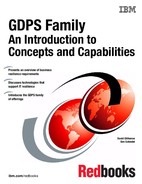
Why is this necessary? Consider the configuration shown in Figure 3-1. This is what might happen if only the volumes of a single LSS or subsystem were hyperswapped without swapping the whole consistency group. What happens if there is a remote copy failure at 15:00? The secondary disks in both sites are frozen at 15:00 and the primary disks (in the case of a FREEZE and GO policy) continue to receive updates.
Now assume that either site is hit by another failure at 15:10. What do you have? Half the disks are now at 15:00 and the other half are at 15:10 and neither site has consistent data. In other words, the volumes are of virtually no value to you.
If you had all the secondaries in Site2, all volumes in that site would be consistent. If you had the disaster at 15:10, you would lose 10 minutes of data with the GO policy, but at least all the data in Site2 would be usable. Using a FREEZE and STOP policy is no better for this partial swap scenario because with a mix of primary disks in either site, you have to maintain I/O configurations that can match every possible combination simply to IPL any systems.
More likely, you first have to restore mirroring across the entire consistency group before recovering systems and this is not really practical. Therefore, for disaster recovery readiness, it is necessary that all the primary volumes are in one site, and all the secondaries in the other site.

Figure 3-1 Unworkable Metro Mirror disk configuration
HyperSwap with less than full channel bandwidth
You may consider enabling unplanned HyperSwap even if you do not have sufficient cross-site channel bandwidth to sustain the full production workload for normal operations. Assuming that a disk failure is likely to cause an outage and you will need to switch to using disk in the other site, the unplanned HyperSwap might at least present you with the opportunity to perform an orderly shutdown of your systems first. Shutting down your systems cleanly avoids the complications and restart time elongation associated with a crash-restart of application subsystems.
HyperSwap policy (PRIMARYFAILURE policy) options
Clients might prefer not to immediately enable their environment for unplanned HyperSwap when they first implement GDPS. For this reason, HyperSwap is not enabled by default. However, we strongly recommend that all GDPS/PPRC clients enable their environment for unplanned HyperSwap.
An unplanned swap is the action that makes most sense when a primary disk problem is encountered. However, other policy specifications that will not result in a swap are available. When GDPS detects a primary disk problem trigger, the first thing it will do will be a Freeze (the same as is performed when a mirroring problem trigger is encountered). GDPS then uses the selected PRIMARYFAILURE policy option to determine what action it will take next:
•PRIMARYFAILURE=GO
No swap is performed. The action GDPS takes is the same as for a freeze event with policy option PPRCFAILURE = GO. A RUN is performed, which will allow systems to continue using the original primary disks. PPRC is suspended and therefore updates are not being replicated to the secondary. Note, however, that depending on the scope of the primary disk problem, it might be that some or all production workloads simply cannot run or cannot sustain required service levels. Such a situation might necessitate restarting the systems on the secondary disks. Due to the freeze, the secondary disks are in a consistent state and can be used for restart. However, any transactions that ran after the GO action will be lost.
•PRIMARYFAILURE=STOP
No swap is performed. The action GDPS takes is the same as for a freeze event with policy option PPRCFAILURE=STOP. GDPS system-RESETs all the production systems. This ensures that no further I/O occurs. After performing situation analysis, if it is determined that this was not a transient issue and that the secondaries should be used to re-IPL the systems, no data will be lost.
•PRIMARYFAILURE=SWAP,swap_disabled_action
The first parameter, SWAP, indicates that after performing the Freeze, GDPS will proceed with performing an unplanned HyperSwap. When the swap is complete, the systems will be running on the new, swapped-to primary disks (former secondaries). PPRC will be in a suspended state; because the primary disks are known to be in a problematic state, there is no attempt to reverse mirroring. After the problem with the primary disks is fixed, you can instruct GDPS to resynchronize PPRC from the current primaries to the former ones (which are now considered to be secondaries).
The second part of this policy, swap_disabled_action, indicates what GDPS should do if HyperSwap had been temporarily disabled by operator action at the time the trigger was encountered. Effectively, an operator action has instructed GDPS not to perform a HyperSwap, even if there is a swap trigger. GDPS has already performed a freeze. The second part of the policy control what action GDPS will take next.
The following options (which only come into play if HyperSwap was disabled by the operator) are available for the second parameter (remember that the disk is already frozen):
GO This is the same action as GDPS would have performed if the policy option had been specified as PRIMARYFAILURE=GO.
STOP This is the same action as GDPS would have performed if the policy option had been specified as PRIMARYFAILURE=STOP.
PRIMARYFAILURE policy specification considerations
As indicated previously, the action that best serves RTO/RPO objectives when there is a primary disk problem is to perform an unplanned HyperSwap. Hence, the SWAP policy option is the recommended policy option.
For the STOP or GO choice, either as the second part of the SWAP specification or if you will not be using SWAP, similar considerations apply as discussed for the PPRCFAILURE policy options to STOP or GO. GO carries the risk of data loss if it should be necessary to abandon the primary disk and restart systems on the secondary. STOP carries the risk of taking an unnecessary outage if the problem was transient. The key difference is that with a mirroring failure, the primary disks are not broken. When you allow the systems to continue to run on the primary disk with the GO option, other than a disaster which is low probability, the systems are likely to run with no problems. With a primary disk problem, with the GO option, you are allowing the systems to continue running on what are known to be disks that experienced a problem just seconds ago. If this was a serious problem with widespread impact such as an entire disk subsystem failure, the applications are going to experience severe problems. Some transactions might continue to commit data to those disks that are not broken. Other transactions might be failing or experiencing serious service time issues. Finally, if there is a decision to restart systems on the secondary because the primary disks are simply not able to support the workloads, there will be data loss. The probability that a primary disk problem is a real problem that will necessitate restart on the secondary disks is much higher when compared to a mirroring problem. A GO specification in the PRIMARYFAILURE policy increases your overall risk for data loss.
If the primary failure was of a transient nature, a STOP specification results in an unnecessary outage. However, with primary disk problems the probability that the problem could necessitate restart on the secondary disks is high, so a STOP specification in the PRIMARYFAILURE policy avoids data loss and facilitates faster restart.
The considerations relating to CF structures with a PRIMARYFAILURE event are similar to a PPRCFAILURE event. If there is an actual swap, the systems continue to run and continue to use the same structures as they did prior to the swap; the swap is transparent, With a GO action, because you continue to update the CF structures along with the primary disks after the GO, if you need to abandon the primary disks and restart on the secondary, the structures are inconsistent with the secondary disks and are not usable for restart purposes. This will elongate the restart, and therefore your recovery time. With STOP, if you decide to restart the systems using the secondary disks, there is no consistency issue with the CF structures because no further updates occurred on either set of disks once the trigger was captured.
PPRC Failover/Failback support
When a primary disk failure occurs and the disks are switched to the secondary devices, PPRC Failover/Failback (FO/FB) support eliminates the need to do a full copy when reestablishing replication in the opposite direction. Because the primary and secondary volumes are often in the same state when the freeze occurred, the only differences between the volumes are the updates that occur to the secondary devices after the switch. Failover processing sets the secondary devices to primary suspended status and starts change recording for any subsequent changes made. When the mirror is reestablished with failback processing, the original primary devices become secondary devices and a resynchronization of changed tracks takes place.
GDPS/PPRC transparently exploits the PPRC FO/FB capability if it is installed on the disk subsystems. This support mitigates RPO exposures by reducing the amount of time needed to resynchronize mirroring after a HyperSwap. Of course, the resync time will depend on how long mirroring was suspended and the number of changed tracks that must be transferred.
All disk subsystems in your GDPS configuration, in both Site1 and Site2, must support PPRC Failover/Failback for GDPS to exploit this capability.
Protection during IPL
A system cannot be IPLed using a disk that is physically a PPRC secondary disk because PPRC secondary disks cannot be brought online to any systems. However, a disk can be secondary from a GDPS (and application usage) perspective but physically from a PPRC perspective have simplex or primary status.
For both planned and unplanned HyperSwap, and a disk recovery, GDPS changes former secondary disks to primary or simplex state. However, these actions do not modify the state of the former primary devices, which remain in the primary state. Hence the former primary devices remain accessible and usable even though they are considered to be the secondary disks from a GDPS perspective. This makes it is possible to accidentally IPL from the wrong set of disks. Accidentally using the wrong set of disks can result in a potential data integrity or data loss problem.
GDPS/PPRC provides IPL protection in two different ways. If you attempt to LOAD a system through GDPS (either script or panel or GUI) using the wrong set of disks, GDPS rejects the LOAD operation. Additionally, in case you used the HMC, then early in the IPL process, during initialization of GDPS, if GDPS detects that the system coming up has just been IPLed using the wrong set of disks, GDPS will quiesce that system, preventing any data integrity problems that could be experienced had the applications been started.
3.1.2 Protecting tape data
Although most of your critical data will be resident on disk, it is possible that other data you require following a disaster resides on tape. Just as you mirror your disk-resident data to protect it, equally you can mirror your tape-resident data. GDPS/PPRC provides support for a single integrated recovery process when using the IBM TotalStorage 3494-based Virtual Tape Subsystem in a Peer-to-Peer configuration.
Additionally, GDPS provides support for management of the IBM Virtualization Engine TS7700. GDPS provides TS7700 configuration management and displays the status of the managed TS7700s on GDPS panels. TS7700s that are managed by GDPS are monitored and alerts are generated for non-normal conditions. The capability to control TS7700 replication from GDPS scripts and panels using TAPE ENABLE and TAPE DISABLE by library, grid, or site is provided for managing TS7700 during planned and unplanned outage scenarios.
Another important aspect with replicated tape is identification of “in-doubt” tapes. Tape replication is not exactly like disk replication in that the replication is not carried out every time a record is written to the tape. The replication is typically performed at tape unload rewind time or perhaps even later. This means that if there is an unplanned event or interruption to the replication, some volumes could be back-level in one or more libraries in the grid. If you have to perform a recovery operation in one site because the other site has failed, it is important to identify if any of the tapes in the library in the site where you are recovering are back-level. Depending on the situation with any in-doubt tapes in the library or libraries you will use in the recovery site, you might need to perform special recovery actions. For example, you might need to rerun one or more batch jobs before resuming batch operations.
GDPS provides support for identifying in-doubt tapes in a TS7700 library. The TS7700 provides a capability called Bulk Volume Information Retrieval (BVIR). Using this BVIR capability, GDPS, if there is an unplanned interruption to tape replication, automatically collects information about all volumes in all libraries in the grid where the replication problem occurred. GDPS can then use this information to report on in-doubt volumes in any given library in that grid if the end user requests a report. In addition to this automatic collection of in-doubt tape information, it is possible to request GDPS to perform BVIR processing for a selected library using the GDPS panel interface at any time.
The IBM Virtualization Engine TS7700 provides comprehensive support for replication of tape data. See IBM Virtualization Engine TS7700, SG24-7975 for more information about the TS7700 technology that complements GDPS for tape data.
3.1.3 Protecting distributed (FBA) data
|
Terminology note: The introduction of Open LUN support in GDPS has caused several changes in the terminology we use when referring to disks in this book, as explained here.
•System z or CKD disks
GDPS can manage disks that are used by System z systems, although disks could be z/VM, VSE, or Linux on System z disks. All these disks are formatted as Count-Key-Data (CKD) disks, the traditional mainframe format.
In most places, we refer to the disks used by a system running on the mainframe as “System z disks,” although there are a small number of cases where the term “CKD disks” is also used; both terms are used interchangeably.
•Open LUN or FB disks
Disks that are used by systems other than those running on System z are traditionally formatted as Fixed Block Architecture (FBA or FB). In this book, we generally use the term “Open LUN disks” or “FBA disks” or “FB disks” interchangeably to refer to such devices.
GDPS/PPRC provides support for SCSI-attached FB disk used by native Linux for System z systems under GDPS xDR1 control. There is a need to differentiate between FB disk used by other distributed systems (including Linux on System z systems not under xDR control) and the FB disk used by native Linux on System z xDR.
|
1 Refer to 3.3.1, “Multiplatform Resiliency for System z (also known as xDR)” on page 69 for more details.
GDPS/PPRC can manage the mirroring of FB devices used by non-mainframe operating systems; this also includes SCSI disks written by Linux for System z. The FB devices can be part of the same consistency group as the mainframe CKD devices, or they can be managed separately in their own consistency group. Note that CKD and xDR-managed FB disks are always in the same consistency group: they are always frozen and swapped together.
For a more detailed discussion of Open LUN management, see 8.1, “Open LUN Management function” on page 214.
3.1.4 Protecting other CKD data
Systems that are fully managed by GDPS are known as GDPS-managed systems or GDPS systems. These are:
•z/OS systems in the GDPS sysplex
•z/VM systems managed by GDPS/PPRC MultiPlatform Resiliency for System z (xDR)
•Linux on System z systems running natively in an LPAR managed by GDPS/PPRC MultiPlatform Resiliency for System z (xDR)
GDPS/PPRC can also manage the disk mirroring of CKD disks used by systems outside of the sysplex: other z/OS systems, Linux on System z, VM, and VSE systems that are not running any GDPS/PPRC or xDR automation. These are known as “foreign systems.”
Because GDPS manages PPRC for the disks used by these systems, these disks will be attached to the GDPS controlling systems. With this setup, GDPS is able to capture mirroring problems and will perform a freeze. All GDPS-managed disks belonging to the GDPS systems and these foreign systems are frozen together, regardless of whether the mirroring problem is encountered on the GDPS systems’ disks or the foreign systems’ disks.
GDPS/PPRC is not able to directly communicate with these foreign systems. For this reason, GDPS automation will not be aware of certain other conditions such as a primary disk problem that is detected by these systems. Because GDPS will not be aware of such conditions that would have otherwise driven autonomic actions such as HyperSwap, GDPS will not react to these events.
If an unplanned HyperSwap occurs (because it was triggered on a GDPS-managed system), the foreign systems cannot and will not swap to using the secondaries. A setup is prescribed to set a long Extended Long Busy time-out (the maximum is 18 hours) for these systems such that when the GDPS-managed systems swap, these systems hang. The ELB prevents these systems from continuing to use the former primary devices. You can then use GDPS automation facilities to reset these systems and re-IPL them using the swapped-to primary disks.
3.2 GDPS/PPRC configurations
At its most basic, a GDPS/PPRC configuration consists of at least one production system, at least one Controlling system in a sysplex, primary disks, and secondary disks. The actual configuration depends on your business and availability requirements. We list the three most common configurations here.
•Active/Standby configuration
In this configuration, all the production systems normally run in the same site, referred to as Site1, and the GDPS Controlling system runs in Site2.
•Active/Active configuration
In this configuration, the production systems run in both sites, Site1 and Site2. This configuration typically exploits the full benefits of data sharing available with a Parallel Sysplex. It is recommended to have two GDPS Controlling systems, one in each site.
•Business Recovery Services (BRS) configuration
In this configuration, the production systems and the Controlling system are all in the same site, referred to as Site1. Site2 can be a client site or can be owned by a third-party recovery services provider (thus the name BRS).
These configuration options are described in further detail in the following sections.
3.2.1 Controlling system
Why does a GDPS/PPRC configuration need a Controlling system? At first, you might think this is an additional infrastructure overhead. However, when you have an unplanned outage that affects production systems or the disk subsystems, it is crucial to have a system such as the Controlling system that can survive failures that might have impacted other portions of your infrastructure. The Controlling system allows you to perform situation analysis after the unplanned event to determine the status of the production systems or the disks, and then to drive automated recovery actions. The Controlling system plays a vital role in a GDPS/PPRC configuration.
The Controlling system must be in the same sysplex as the production system (or systems) so it can see all the messages from those systems and communicate with those systems. However, it shares an absolute minimum number of resources with the production systems (typically just the sysplex couple data sets). By being configured to be as self-contained as possible, the Controlling system will be unaffected by errors that can stop the production systems (for example, an Extended Long Busy event on a primary volume).
The Controlling system must have connectivity to all the Site1 and Site2 primary and secondary devices that it will manage. If available, it is preferable to isolate the Controlling system infrastructure on a disk subsystem that is not housing mirrored disks that are managed by GDPS.
The Controlling system is responsible for carrying out all recovery actions following a disaster or potential disaster; for managing the disk mirroring configuration; for initiating a HyperSwap; for initiating a freeze and implementing the freeze/swap policy actions; reassigning STP roles; re-IPLing failed systems, and so on.
The availability of the dedicated GDPS Controlling system (or systems) in all configurations is a fundamental requirement of GDPS. It is not possible to merge the function of the Controlling system with any other system that accesses or uses the primary volumes.
Improved Controlling system availability - enhanced timer support
In a GDPS environment, z/OS is aware that a given system is a GDPS Controlling system and allows a GDPS Controlling system to continue processing even when the server it is running on loses its time source and becomes unsynchronized. The Controlling system is therefore able to complete any freeze or HyperSwap processing it might have started or to run a recovery script, instead of being placed in a disabled WTOR state.
Normally, a loss of synchronization with the sysplex timing source will generate a disabled console WTOR that suspends all processing on the LPAR, until a response is made to the WTOR. The WTOR message is IEA015A if the CPC that z/OS is running on is in ETR timing mode (either in an ETR network or in an STP Mixed Coordinated Timing Network (CTN)). The WTOR message is IEA394A if the CPC is in STP timing mode (either in an STP Mixed CTN or STP-only CTN).
In a GDPS environment, z/OS is aware that a given system is a GDPS Controlling system and will allow a GDPS Controlling system to continue processing even when the server it is running on loses its time source and becomes unsynchronized. The Controlling system is therefore able to complete any freeze or HyperSwap processing it might have started and is available for situation analysis and other recovery actions, instead of being in a disabled WTOR state.
In addition, because the Controlling system is operational, it can be used to help in problem determination and situation analysis during the outage, thus reducing further the recovery time needed to restart applications.
The Controlling system is required to perform GDPS automation in the event of a failure. Actions may include:
•Reassigning STP roles
•Performing the freeze processing to guarantee secondary data consistency
•Coordinating HyperSwap processing
•Executing a takeover script
•Aiding with situation analysis
Because the Controlling system only needs to run with a degree of time synchronization that allows it to correctly participate in heartbeat processing with respect to the other systems in the sysplex, this system should be able to run unsynchronized for a period of time (80 minutes) using the local TOD clock of the server (referred to as local timing mode), instead of generating a WTOR.
Automated response to ETR or STP sync WTORs
GDPS on the Controlling systems, using the BCP Internal Interface, provides automation to reply to WTORs IEA015A or IEA394A when the Controlling systems are running in local timing mode. Refer to “Improved Controlling system availability - enhanced timer support” on page 64. A server in an ETR or STP network might have recovered from an unsynchronized to a synchronized timing state without client intervention. By automating the response to the WTORs, potential time outs of subsystems and applications in the client’s enterprise might be averted, thus potentially preventing a production outage.
If either WTOR IEA015A or IEA394A is posted for production systems, GDPS uses the BCP Internal Interface to automatically reply RETRY to the WTOR. If z/OS determines that the CPC is in a synchronized state, either because STP recovered or the CTN was reconfigured, it will no longer spin and continue processing. If the CPC is still in an unsynchronized state when GDPS automation responded with RETRY to the WTOR, however, the WTOR will be reposted.
The automated reply for any given system is retried for 60 minutes. After 60 minutes, you will need to manually respond to the WTOR.
3.2.2 Active/standby configuration
A GDPS/PPRC active/standby workload environment typically consists of a multisite sysplex, with all production systems normally running in Site1, and the GDPS Controlling system in Site2. The Controlling system (or systems, because you may have two in some configurations) will normally run in the site containing the secondary disk volumes.
The multisite sysplex can be a base sysplex or a Parallel Sysplex; a Coupling Facility is not strictly required. The multisite sysplex must be configured with redundant hardware (for example, a Coupling Facility and a Sysplex Timer in each site), and the cross-site connections must also be redundant. Instead of using Sysplex Timers to synchronize the servers, you can also use Server Time Protocol (STP) to synchronize the servers.
Figure 3-2 on page 66 shows a typical GDPS/PPRC active/standby workload configuration. The LPARs in blue (P1, P2, P3, and K1) are in the production sysplex, as are the Coupling Facilities CF1 and CF2. The primary disks are all in Site1, with the secondaries in Site2. All the production systems are running in Site1, with simply the GDPS Controlling system (K1) running in Site2. You will notice that system K1’s disks (those marked K) are also in Site2. The unlabeled boxes represent work that can be displaced, such as development or test systems.
The GDPS/PPRC code itself runs under NetView and System Automation, and runs in every system in the GDPS sysplex.
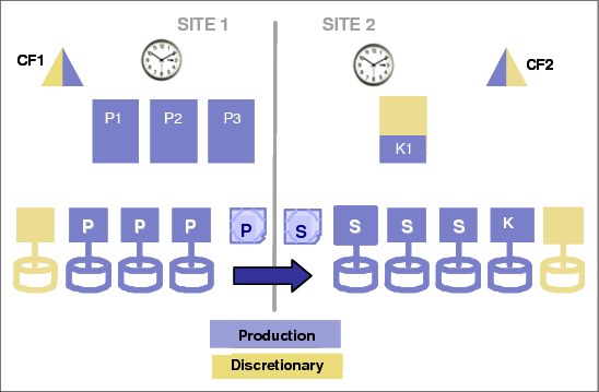
Figure 3-2 GDPS/PPRC active/standby workload configuration
3.2.3 Active/active configuration
An active/active workload configuration, shown in Figure 3-3 on page 67, differs from an active/standby workload in that production systems are running in both sites. Also, although it is possible to run an active/standby workload as a base sysplex, it is unusual to see an active/active workload using a base sysplex (that is, without coupling facilities). This is because an active/active workload is usually a result of higher availability requirements, and Parallel Sysplex and data sharing are core components of such an environment.
Because in this example we have production systems in both sites, we need to provide the capability to recover from a failure in either site. So, in this case, there is also a GDPS Controlling system with its own local (not mirrored) disk running in Site1, namely System K2. Therefore, if there is a disaster that disables Site2, there will still be a GDPS Controlling system available to decide how to react to that failure and what recovery actions are to be taken.

Figure 3-3 GDPS/PPRC active/active workload configuration
3.2.4 Business Recovery Services (BRS) configuration
A third configuration is what is known as the “BRS configuration”, illustrated in Figure 3-4 on page 68. In this configuration, all the systems in the GDPS configuration, including the Controlling system, are in a sysplex in the same site, namely Site1. The sysplex does not span the two sites. The second site, Site2, might be a client site or might be owned by a third-party recovery services provider; thus the name BRS.
Site2 will contain the secondary disks and the alternate Couple Data Sets (CDS), and might also contain processors that will be available in case of a disaster, but are not part of the configuration. This configuration can also be used when the distance between the two sites exceeds the distance supported for a multisite sysplex, but is within the maximum distance supported by FICON and Metro Mirror.
Even though there is no need for a multisite sysplex with this configuration, you must have channel connectivity from the GDPS systems to the secondary disk subsystems. Also, as explained in the next paragraph, the Controlling system in Site1 will need channel connectivity to its disk devices in Site2. Therefore, FICON link connectivity from Site1 to Site2 will be required. Refer to 2.9.8, “Connectivity options” on page 46, and IBM System z Connectivity Handbook, SG24-5444, for options available to extend the distance of FICON links between sites.
In the BRS configuration, the Controlling system (K1) should have its disk devices in Site2. This permits the K1 system to be restarted manually in Site2 after a disaster has been declared. The K1 system will then be used to recover the secondary disk subsystems to a simplex state when necessary and then, using a GDPS control script, reconfigure the recovery site and restart the production systems from the disk subsystems in Site2.
If you have only a single Controlling system and you have a total cross-site fiber connectivity failure, the K1 system might not be able to complete the Freeze operation because it will lose access to its disk in Site2. Having a second Controlling system running in Site1 (K2 in Figure 3-4) on local disks in Site1 will guarantee that the freeze operation completes successfully in the event the Controlling system running on Site2 disks is down or is unable to function due to a cross-site fiber loss. GDPS will attempt to maintain the current Master system in the Controlling system by using the secondary disks.

Figure 3-4 GDPS/PPRC BRS configuration
3.2.5 GDPS/PPRC in a three-site configuration
GDPS/PPRC can be combined with GDPS/XRC or GDPS/GM in a three-site configuration. In this configuration, GDPS/PPRC (when combined with Parallel Sysplex exploitation and HyperSwap) provides continuous availability across a metropolitan area or within the same local site, and GDPS/XRC or GDPS/GM provides disaster recovery capability using a remote site.
We call these combinations GDPS/Metro Global Mirror (GDPS/MGM) or GDPS/Metro z/OS Global Mirror (GDPS/MzGM). In these configurations, GDPS/PPRC, GDPS/XRC, and GDPS/GM provide additional automation capabilities.
Refer to Chapter 9, “Combining Local/Metro continuous availability with out-of-region disaster recovery” on page 245 for a more detailed discussion about GDPS/MGM and GDPS/MzGM.
3.2.6 GDPS/PPRC in a single site
The final configuration is where you want to benefit from the capabilities of GDPS/PPRC to extend the continuous availability attributes of a Parallel Sysplex to planned and unplanned disk reconfigurations, but you do not have the facilities to mirror disk across two sites. In this case, you can implement GDPS/PPRC HyperSwap Manager (GDPS/PPRC HM).
GDPS/PPRC HM is similar to the full function GDPS/PPRC offering, except that it does not include the scripts for management of the LPARs and workloads. GDPS/PPRC HM is upgradeable to a full GDPS/PPRC implementation. GDPS/PPRC HM is discussed in Chapter 4, “GDPS/PPRC HyperSwap Manager” on page 95.
3.2.7 Other considerations
The availability of the dedicated GDPS Controlling system (or systems) in all scenarios is a fundamental requirement in GDPS. It is not possible to merge the function of the Controlling system with any other system that accesses or uses the primary volumes.
Equally important is that certain functions (stopping and restarting systems and changing the Couple Data Set configuration) are carried out through the scripts and panel interface provided by GDPS. Because events such as systems going down or changes to the Couple Data Set configuration are indicators of a potential disaster, such changes must be initiated using GDPS functions so that GDPS understands that these are planned events.
3.3 GDPS/PPRC management of distributed systems and data
As mentioned in 3.1.3, “Protecting distributed (FBA) data” on page 62, it is possible for GDPS/PPRC to manage FB disks on behalf of distributed systems either in the same consistency group as the System z CKD disks or in a separate group.
GDPS/PPRC also provides capabilities to extend management of distributed systems in the following ways:
•GDPS/PPRC Multiplatform Resiliency for System z (also known as xDR)
•GDPS/PPRC Distributed Cluster management (DCM)
3.3.1 Multiplatform Resiliency for System z (also known as xDR)
To reduce IT costs and complexity, many enterprises are consolidating open servers into Linux on System z servers. Linux on System z systems can either be implemented as guests running under z/VM, or native Linux on System z systems. There are several examples of an application server running on Linux on System z and a database server running on z/OS, such as:
•WebSphere Application Server running on Linux and CICS, DB2 running under z/OS
•SAP application servers running on Linux and database servers running on z/OS
With a multitiered architecture, there is a need to provide a coordinated near-continuous availability and disaster recovery solution for both z/OS and Linux on System z. The GDPS/PPRC function that provides this capability is called Multiplatform Resiliency for System z, and it can be implemented as long as the disks being used by z/VM and Linux are CKD disks. For more details about this function, refer to 8.2, “GDPS/PPRC Multiplatform Resiliency for System z” on page 216.
3.3.2 Distributed Cluster Management
GDPS Distributed Cluster Management (DCM) is a capability that allows the management and coordination of disaster recovery across clustered distributed servers and the System z workload (or workloads) that GDPS is responsible for.
The DCM support is provided in GDPS/PPRC for both Symantec Veritas Cluster Server (VCS) clusters and IBM Tivoli System Automation Application Manager (SA AppMan). GDPS/PPRC can support both VCS and SA AppMan concurrently. DCM provides advisory and coordination functions between GDPS and one or more VCS and/or SA AppMan managed clusters.
For a more detailed discussion of the DCM function, refer to 8.3, “Distributed Cluster Management” on page 222.
3.4 Managing the GDPS environment
We have seen how GDPS/PPRC can protect just about any type of data that can reside in a disk subsystem. Further, it can provide data consistency across all platforms. However, as discussed in Chapter 1, “Introduction to business resilience and the role of GDPS” on page 1, the overwhelming majority of System z outages are not disasters. Most are planned outages, with a small percentage of unplanned ones.
In this section, we describe the other aspect of GDPS/PPRC, that is, its ability to monitor and manage the resources in its environment. GDPS provides two mechanisms to help you manage the GDPS sysplex and resources within that sysplex. One mechanism is the NetView interface, and the other is support for scripts. We review both of these mechanisms here.
3.4.1 NetView interface
There are two primary user interface options available for GDPS/PPRC, the NetView 3270 panels and a browser-based graphical user interface (also referred to as the “web interface” in this document).
An example of the main GDPS/PPRC 3270-based panel is shown in Figure 3-5.

Figure 3-5 Main GDPS/PPRC 3270-based panel
This panel is relatively simple to use, with a summary of configuration status at the top of the panel and a menu of choices that a user can select from. As an example, to view the disk mirroring (Dasd Remote Copy) panels a user simply types 1 at the Selection ===> prompt and presses Enter.
GDPS web interface
The web interface is a browser-based interface designed to improve operator productivity. The web interface provides the same functional capability as the 3270-based panel, such as providing management capabilities for Remote Copy Management, Standard Actions, Sysplex Resource Management, and SDF Monitoring using simple point-and-click procedures. In addition, users can open multiple windows to allow for continuous status monitoring, while performing other GDPS/PPRC management functions.
The web interface display has three sections:
•A menu bar on the left with links to the main GDPS options
•A window list on top allowing switching between multiple open frames
•An active task frame where the relevant information is displayed and activities are performed for a selected option
The main status panel of the GDPS/PPRC web interface is shown in Figure 3-6 on page 72. The left frame, shown under GDPS PPRC links, allows you to select the menu options. These options can be displayed at all times, or you can optionally collapse the frame.
|
Note: For the remainder of this section, only the web interface is shown to illustrate the various GDPS management functions. The equivalent traditional 3270 panels are not shown here.
|

Figure 3-6 Full view of GDPS main panel with task bar and status information
Main Status panel
The GDPS web interface status frame shown in Figure 3-7 is the equivalent of the main GDPS panel. The information displayed on this frame is the same as that found on the top portion of the 3270 GDPS Main panel.
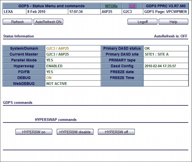
Figure 3-7 GDPS web interface: Main status frame
Monitoring function - Status Display Facility
GDPS also provides many monitors to check the status of disks, sysplex resources, and so on. Any time there is a configuration change, or something in GDPS that requires manual intervention, GDPS will raise an alert. GDPS uses the Status Display Facility (SDF) provided by System Automation as the primary status feedback mechanism for GDPS. It is the only dynamically updated status display available for GDPS.
SDF provides a dynamically updated color-coded panel, as shown in Figure 3-8 on page 74. If something changes in the environment that requires attention, the color of the associated field on the panel will change. At all times, the operators are to have an SDF panel within view so they will immediately become aware of anything requiring intervention or action.
The web interface can be set up to automatically refresh every 30 seconds. As with the 3270 panel, if there is a configuration change or a condition that requires special attention, the color of the fields will change based on the severity of the alert. By pointing to and clicking any of the highlighted fields, you can obtain detailed information regarding the alert.
Figure 3-8 NetView SDF web interface
Remote copy panels
The z/OS Advanced Copy Services capabilities are powerful, but the native Command Line Interface, z/OS TSO, and ICKDSF interfaces are not user friendly. To make it easier for operators to check and manage the remote copy environment, use the GDPS-provided DASD Remote Copy panels.
For GDPS to manage the remote copy environment, you must first define the configuration (primary and secondary LSSs, primary and secondary devices, and PPRC links) to GDPS in a file called the GEOPARM file.
After the configuration is known to GDPS, you can use the panels to check that the current configuration matches the desired one. You can start, stop, suspend, and resynchronize mirroring at the volume or LSS level. These actions can be carried out at the device or LSS level, or both, as appropriate. Figure 3-9 shows the mirroring panel for CKD devices.
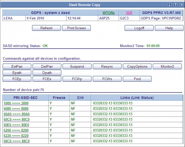
Figure 3-9 Dasd Remote Copy SSID web interface
The Dasd Remote Copy frame is organized into three sections:
•A top section displays the mirroring status, and buttons for Return, Print Screen, Logoff, and Help.
•A middle section displays actions against all the panel-displayed SSID-pairs (similar to the bottom section of the equivalent 3270 panel).
•A bottom section displays the list of all the SSID-pairs.
To perform an action on a single SSID-pair, click the pair. This brings you to a panel where you can perform the same actions as those available as line commands on the top section of the 3270 panel.
After an individual SSID-pair has been selected, the frame shown in Figure 3-10 is displayed. The bottom of this frame shows each of the mirrored device pairs within a single SSID-pair, along with the current status of each pair. In this example, all the pairs are fully synchronized and in duplex status (indicated as DUP on the panel). Also note that the secondary devices for some of these pairs are in an alternate subchannel set (MSS1, in this case). Additional details can be viewed for each pair by clicking the button for the primary device in the pair.
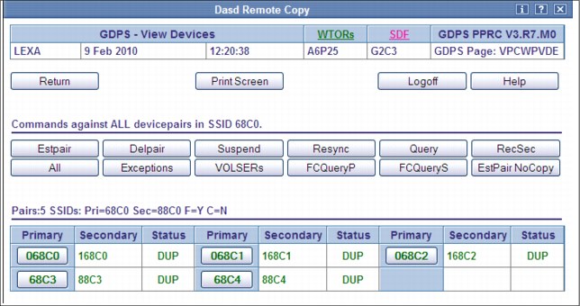
Figure 3-10 Web Interface Dasd Remote Copy “View Devices” detail frame
If you are familiar with using the TSO or ICKDSF interfaces you will appreciate how much more user friendly these panels are.
Remember that these GDPS-provided panels are not intended to be a remote copy monitoring tool. Because of the overhead involved in gathering the information for every device to populate the NetView panels, GDPS only gathers this data on a timed basis, or on demand following an operator instruction. The normal interface for finding out about remote copy status or problems is the Status Display Facility (SDF).
Similar panels are provided for controlling the FB devices.
Standard Actions
GDPS provides facilities to help manage many common system-related planned actions. There are two reasons to use the GDPS facilities to perform these Standard Actions:
•They are well tested and based on IBM recommended procedures.
•Using the GDPS interface lets GDPS know that the changes that it is seeing (Couple Data Sets (CDS) being deallocated or systems going out of the sysplex, for example) are planned changes, and therefore GDPS is not to react to these events.
There are two types of resource-altering actions you can initiate from the panels. Those that GDPS calls Standard Actions are actually single steps, or are intended to impact only one resource. Examples are starting a system IPL, maintaining the various IPL address and load parameters that can be used to IPL a system, selecting the IPL address and load parameters to be used the next time a system IPL is started, or activating an LPAR. So if you want to stop a system, change its IPL address, then perform an IPL, you initiate three separate Standard Actions.
The GDPS/PPRC Standard Actions 3270 panel is shown in Figure 3-11. It displays all the systems being managed by GDPS/PPRC, and for each one it shows the current status and various IPL information. To perform actions on each system, you simply use a line command letter (L to load, X to reset and so on) next to the selected system.

Figure 3-11 GDPS/PPRC Standard Actions panel
GDPS supports taking a stand-alone dump using the GDPS Standard Actions panel. The stand-alone dump can be performed for any System z operating system defined to GDPS, either a GDPS system or a foreign system, running native in an LPAR. Clients using GDPS facilities to perform HMC actions no longer need to use the HMC for taking stand-alone dumps.
Sysplex resource management
There are certain resources that are vital to the health and availability of the sysplex. In a multisite sysplex, it can be quite complex trying to manage these resources to provide the required availability while ensuring that any changes do not introduce a single point of failure.
The GDPS/PPRC Sysplex Resource Management web interface, shown in Figure 3-12 on page 78, provides you with the ability to manage the resources, with knowledge about where the resources exist. For example, normally you have your Primary CDS in Site1, and your alternates in Site2. However, if you will be shutting down Site1, you still want to have a Primary and Secondary set of CDS, but both must be in Site2. The GDPS Sysplex Resource Management panels provide this capability, without you having to know specifically where each CDS is located.
GDPS provides facilities to manage Coupling Facilities (CFs) in your sysplex. These facilities allow for isolating all of your structures in the CF or CFs in a single site and returning to your normal configuration with structures spread across (and possibly duplexed across) the CFs in the two sites.
Isolating structures into CFs in one site, or returning to normal use with structures spread across CFs in both sites, can be accomplished through the GDPS Sysplex Resource Management panel interface or GDPS scripts. This provides an automated means for managing CFs for planned and unplanned site or disk subsystem outages.
The maintenance mode switch allows you to start or stop maintenance mode on a single CF (or multiple CFs, if all selected CFs are in the same site). DRAIN, ENABLE, and POPULATE function is still available for single CFs.
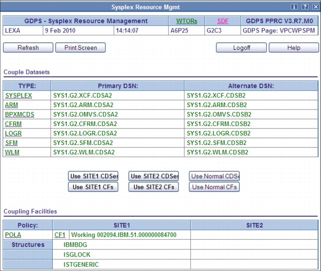
Figure 3-12 GDPS/PPRC Sysplex Resource Management web interface
3.4.2 GDPS scripts
At this point we have shown how GDPS panels provide powerful functions to help you manage GDPS resources. However, using GDPS panels is only one way of accessing this capability. Especially when you need to initiate what might be a complex, compound, multistep procedure, it is much simpler to use a script which in effect is a workflow.
Nearly all of the main functions that can be initiated through the GDPS panels are also available using GDPS scripts. Scripts also provide additional capabilities that are not available using the panels.
A “script” is simply a procedure recognized by GDPS that pulls together one or more GDPS functions. Scripts can be initiated manually for a planned activity through the GDPS panels (using the Planned Actions interface), automatically by GDPS in response to an event (Unplanned Actions), or through a batch interface. GDPS performs the first statement in the list, checks the result, and only if it is successful, proceeds to the next statement. If you perform the same steps manually, you would have to check results, which can be time-consuming, and initiate the next action. With scripts, the process is automated.
Scripts can easily be customized to automate the handling of various situations, both to handle planned changes and unplanned situations. This is an extremely important aspect of GDPS. Scripts are powerful because they can access the full capability of GDPS. The ability to invoke all the GDPS functions through a script provides the following benefits:
•Speed
The script will execute the requested actions and check results at machine speeds. Unlike a human, it does not need to search for the latest procedures or the commands manual.
•Consistency
If you were to look into most computer rooms immediately following a system outage, what would you see? Mayhem, with operators frantically scrambling for the latest system programmer instructions. All the phones ringing. Every manager within reach asking when the service will be restored. And every systems programmer with access vying for control of the keyboards. All this results in errors because humans naturally make mistakes when under pressure. But with automation, your well-tested procedures will execute in exactly the same way, time after time, regardless of how much you shout at them.
•Thoroughly tested procedures
Because they behave in a consistent manner, you can test your procedures over and over until you are sure they do everything that you want, in exactly the manner that you want. Also, because you need to code everything and cannot assume a level of knowledge (as you might with instructions intended for a human), you are forced to thoroughly think out every aspect of the action the script is intended to undertake. And because of the repeatability and ease of use of the scripts, they lend themselves more easily to frequent testing than manual procedures.
Planned Actions
As mentioned earlier, GDPS scripts are simply procedures that pull together into a list one or more GDPS functions. For the scripted procedures that you might use for a planned change, these scripts can be initiated from the panels called Planned Actions (option 6 on the main GDPS panel as shown in Figure 3-5 on page 71).
As one example, you can have a short script that stops an LPAR and then re-IPLs it in an alternate LPAR location, as shown in Example 3-1.
Example 3-1 Sample script to re-IPL a system
COMM=’Example script to re-IPL system SYS1 on alternate ABNORMAL LPAR location’
SYSPLEX=’STOP SYS1’
IPLTYPE=’SYS1 ABNORMAL’
SYSPLEX=’LOAD SYS1’
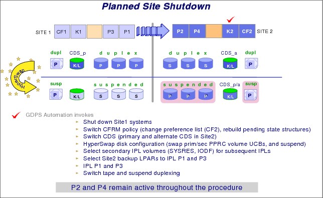
Figure 3-13 GDPS/PPRC Planned Action
A more complex example of a Planned Action is shown in Figure 3-13. In this example, a single action in GDPS executing a planned script of only a few lines results in a complete planned site switch. Specifically, the following actions are carried out by GDPS:
•The systems in Site1, P1 and P3, are stopped (note that P2 and P4 remain active in this example).
•The sysplex resources (CDS and CF) are switched to only use those in Site2.
•A HyperSwap is executed to use the disk in Site2.
•The IPL parameters (IPL address and load parameters) are updated to reflect the new configuration.
•The IPL location for the P1 and P3 systems are changed to the backup LPAR location in Site2.
•P1 and P3 are IPLed in Site2 using the disk in Site2.
Using GDPS removes the reliance on out-of-date documentation, provides a single repository for information about IPL addresses and load parameters, and ensures that the process is carried out the same way every time with no vital steps accidentally overlooked.
STP CTN role reassignments - planned operations
GDPS provides a script statement that allows you to reconfigure an STP-only CTN by reassigning the STP-only CTN server roles. In an STP CTN servers (CPCs) are assigned special roles to identify which CPC is preferred to be the clock source (Preferred Time Server, or PTS), which CPC is able to take over as the clock source for planned and unplanned events (Backup Time Server, or BTS), which CPC is the active clock source (Current Time Server, or CTS), and which CPC assists in STP recovery (Arbiter).
It is strongly recommended that the server roles be reassigned prior to performing planned disruptive actions on any of these special role servers. Examples of planned disruptive actions are power-on reset (POR) and Activate/Deactivate. The script statement can be integrated as part of your existing control scripts to perform these planned disruptive actions.
For example, if you are planning to deactivate the CPC that is the PTS/CTS, you can now execute a script to perform the following tasks:
•Reassign the PTS/CTS role to a different CPC in the CTN
•Optionally also reassign the BTS and Arbiter roles if required
•Execute script statements you might already have in place today to deactivate the PTS/CTS CPC
After the disruptive action is completed you can execute a second script to restore the STP roles to their normal operational state, as listed here:
•Script statement to activate the CPC
•Reassign the STP server roles to their normal operational state
•Statements you might already have in existing scripts to perform IPLs and so on
Recovery scripts
There are scripts also known as Takeover Scripts that are designed to be invoked in case of a disaster or potential disaster. In the case of a Freeze-inducing event, GDPS/PPRC will immediately issue a freeze for all applicable primary devices. This is done automatically (it is already done when a recovery script starts executing) to protect the integrity of the secondary data.
After the freeze and the action indicated in the freeze policy (STOP or GO) has completed, GDPS will present the operator with a prompt listing the scripts that can be executed at this time. At this time, some situation analysis must be performed before accepting to run one of the proposed scripts. The freeze could be caused by a failing secondary disk or by a disaster in the primary site. The scripts to run for these two conditions will be different. After the analysis is complete, the operator simply has to select the appropriate action and GDPS does the rest. You could view such actions as “pre-planned unplanned actions.”
An example is shown in Figure 3-14. In this example, the operator has selected to abandon Site1 and move everything to Site2. GDPS will isolate CDSs and CF structures in Site2. It will also update all the IPL information to point to what were the secondary volumes in Site2; stop expendable systems (if there are any); invoke capacity backup (CBU) to provide the required capacity on the CPC in Site2; and re-IPL all the production systems in LPARs on that CPC. All these tasks are carried out with a single operator instruction.
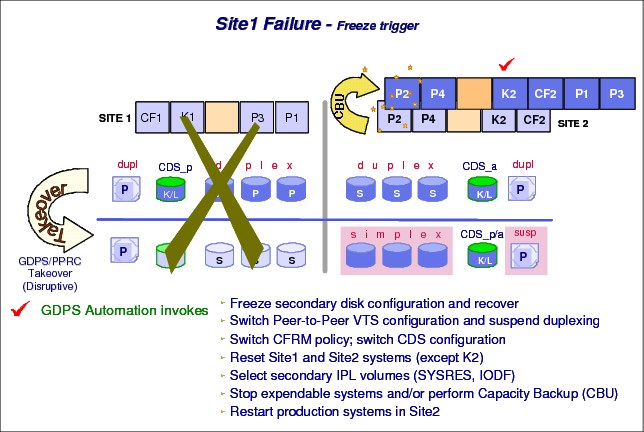
Figure 3-14 GDPS managed recovery from site failure
Another important aspect to disaster recovery is returning to the normal configuration after the unplanned outage. GDPS can help with this as well, again using a GDPS script. The actions in this case are similar, with one important difference. When you moved from Site1 to Site2, the data on the primary and secondary disks was identical (synchronized) at the time of the move. But when you move back, the disks in Site1 do not contain the updates made when production was running using the Site2 disks and must first be resynchronized before the move back to normal. During the period when they are being resynchronized, the secondary volumes have no consistency; remember that the missing updates are not applied in chronological order. What would happen if you had a disaster in Site2 during this window?
If the disaster were a fire, your current primary volumes would be a pool of molten metal on the computer room floor. The secondary disks’ data would be inconsistent. It would be as though you had a random collection of data.
To ensure that you at least have a set of consistent disks in Site1, even if they are not completely current, GDPS can be instructed to first take a FlashCopy of those volumes while they are still consistent before it starts the resynchronization. Thus, if you are unfortunate enough to lose Site2 during this resynchronization period, you at least have a consistent set of disks in Site1 that you can fall back on.
Because it might take a long time for the data to come back to synch, you would need two scripts for your return-to-normal operation: one script to take a FlashCopy and then resynchronize the disk, and a second script which you would initiate to bring systems, disk, and sysplex resources back to normal.
GDPS not only monitors data-related events, but also scripts can be provided to drive recovery from a system failure. As seen in Figure 3-15, when GDPS detects that a z/OS system is no longer active, it verifies whether the policy definition indicates that Auto IPL has been enabled, that the threshold of the number of IPLs in the predefined time window has not been exceeded, and that no planned action is active. If these conditions are met, GDPS can automatically re-IPL the system in place, bring it back into the Parallel Sysplex, and restart the application workload.
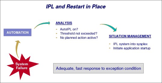
Figure 3-15 Recovering a failed image
Similarly, if a complete processor fails, you can have a script prepared to provide recovery support for all the LPARs on that processor that are managed by GDPS. This script would activate backup partitions for the failed systems, activate CBU if appropriate, and IPL these systems. You could have one such script prepared in advance for every server in your configuration.
STP CTN role reassignments - unplanned failure
If a failure condition has resulted in the PTS, BTS, or Arbiter no longer being an operational synchronized CPC in the CTN, it is recommended that after the failure and possible STP recovery action, the STP roles be reassigned to operational CPCs in the CTN. The reassignment reduces the potential for a sysplex outage in the event a second failure or planned action affects one of the remaining special role CPCs.
The script statement capability described in “STP CTN role reassignments - planned operations” on page 80 can be used to integrate the STP role reassignment as part of an existing script such as a Site takeover script, and eliminate the requirement for the operator to perform the STP reconfiguration task manually at the HMC.
STP WTOR IEA394A response- unplanned failure
As described in “Improved Controlling system availability - enhanced timer support” on page 64, a loss of synchronization with the sysplex timing source will generate a disabled console WTOR. This suspends all processing on the LPAR until a response to the WTOR is provided. The WTOR message is IEA394A if the CPC is in STP timing mode (either in an STP Mixed CTN or STP-only CTN).
GDPS, using scripts, can reply (either ABORT or RETRY) to the IEA394A sync WTOR for STP on systems that are spinning due to a loss of synchronization with their Current Time Source. As described in “Automated response to ETR or STP sync WTORs” on page 65, autonomic function exists to reply RETRY automatically for 60 minutes on any GDPS systems that have posted this WTOR.
The script statement complements and extends this function, as described:
•It provides the means to reply to the message after the 60-minute automatic reply window expires.
•It can reply to the WTOR on systems that are not GDPS systems (foreign systems) that are defined to GDPS; the autonomic function only replies on GDPS systems.
•It provides the ability to reply ABORT on any systems you do not want to restart for a given failure scenario prior to reconfiguration and synchronization of STP.
Batch scripts
GDPS also provides a flexible batch interface to invoke planned action scripts. These scripts can be invoked:
•As a REXX program from a user terminal
•By using the MVS MODIFY command to the NetView task
•From timers in NetView
•Triggered through the SA automation tables
This capability, along with the query services interface described in 3.6.4, “Query Services” on page 89, provides a rich framework for user-customizable systems management procedures.
3.4.3 System Management actions
Most of the GDPS Standard Actions require actions to be carried out on the HMC. The interface between GDPS and the HMC is through the BCP Internal Interface (BCPii), and this allows GDPS to communicate directly with the hardware for automation of HMC actions such as LOAD, STOP (graceful shutdown), RESET, Activate LPAR, and Deactivate LPAR. GDPS can also perform ACTIVATE (power-on reset), CBU ACTIVATE/UNDO, OOCoD ACTIVATE/UNDO, and STP role reassignment actions against an HMC object that represents a CPC.
The GDPS LOAD and RESET Standard Actions (available through the Standard Actions panel or the SYSPLEX script statement) allow specification of a CLEAR or NOCLEAR operand. This provides operational flexibility to accommodate client procedures, thus eliminating the requirement to use the HMC to perform specific LOAD and RESET actions.
Furthermore, when you LOAD a system using GDPS (panels or scripts), GDPS can listen for operator prompts from the system being IPLed and reply to such prompts. GDPS provides support for optionally replying to such IPL-time prompts automatically, removing reliance on operator skills and eliminating operator error for any messages that require replies.
SYSRES Management
Today many clients maintain multiple alternate z/OS SYSRES devices (also known as IPLSETs) as part of their maintenance methodology. GDPS provides special support to allow clients to identify IPLSETs. This removes the requirement for clients to manage and maintain their own procedures when IPLing a system on a different alternate SYSRES device.
GDPS can automatically update the IPL pointers after any disk switch or disk recovery action that changes the GDPS primary site indicator for PPRC disks. This removes the requirement for clients to perform additional script actions to switch IPL pointers after disk switches, and greatly simplifies operations for managing alternate SYSRES “sets.”
3.5 GDPS/PPRC monitoring and alerting
The GDPS SDF panel, discussed in “Monitoring function - Status Display Facility” on page 73, is where GDPS dynamically displays color-coded alerts.
Alerts can be posted as a result of an unsolicited error situation that GDPS listens for. For example, if one of the multiple PPRC links that provide the path over which PPRC operations take place is broken, there is an unsolicited error message issued. GDPS listens for this condition and will raise an alert on the SDF panel, notifying the operator of the fact that a PPRC link is not operational. Clients run with multiple PPRC links and if one is broken, PPRC continues over any remaining links.
However, it is important for operations to be aware that a link is broken and fix this situation because a reduced number of links results in reduced PPRC bandwidth and reduced redundancy. If this problem is not fixed in a timely manner and more links have a failure, it can result in production impact due to insufficient mirroring bandwidth or total loss of PPRC connectivity (which results in a freeze).
Alerts can also be posted as a result of GDPS periodically monitoring key resources and indicators that relate to the GDPS/PPRC environment. If any of these monitoring items are found to be in a state deemed to be not normal by GDPS, an alert is posted on SDF.
Various GDPS monitoring functions are executed, not only on the GDPS Controlling systems, but also on the production systems. This is because, from a software perspective, it is possible that different production systems have different views of some of the resources in the environment, and although status can be normal in one production system, it can be not normal in another. All GDPS alerts generated on one system in the GDPS sysplex are propagated to all other systems in the GDPS. This propagation of alerts provides for a single focal point of control. It is sufficient for the operator to monitor SDF on the master Controlling system to be aware of all alerts generated in the entire GDPS complex.
When an alert is posted, the operator will have to investigate (or escalate, as appropriate) and corrective action will need to be taken for the reported problem as soon as possible. After the problem is corrected, this is detected during the next monitoring cycle and the alert is cleared by GDPS automatically.
GDPS/PPRC monitoring and alerting capability is intended to ensure that operations are notified of and can take corrective action for any problems in their environment that can impact the ability of GDPS/PPRC to carry out recovery operations. This will maximize the chance of achieving your availability and RPO/RTO commitments.
3.5.1 GDPS/PPRC health checks
In addition to the GDPS/PPRC monitoring described, GDPS provides health checks. These health checks are provided as a plug-in to the z/OS Health Checker infrastructure to check that certain GDPS-related settings adhere to best practices.
The z/OS Health Checker infrastructure is intended to check a variety of settings to determine whether these settings adhere to z/OS best practices values. For settings found to be not in line with best practices, exceptions are raised in the Spool Display and Search Facility (SDSF). If these settings do not adhere to recommendations, this can hamper the ability of GDPS to perform critical functions in a timely manner.
Often, if there are changes in the client environment, this might necessitate adjustment of various parameter settings associated with z/OS, GDPS, and other products. It is possible that you can miss making these adjustments, which can affect GDPS. The GDPS health checks are intended to detect such situations and avoid incidents where GDPS is unable to perform its job due to a setting that is perhaps less than ideal.
For example, GDPS/PPRC provides facilities for management of the Couple Data Sets (CDS) for the GDPS sysplex. One of the health checks provided by GDPS/PPRC checks that the CDS are allocated and defined to GDPS in line with the GDPS best practices recommendations.
Similar to z/OS and other products that provide health checks, GDPS health checks are optional. Additionally, a number of the best practices values that are checked, and the frequency of the checks, are client-customizable to cater to unique client environments and requirements.
There are a few z/OS best practices that conflict with GDPS best practices. The related z/OS and GDPS health checks result in conflicting exceptions being raised. For such health check items, to avoid conflicting exceptions, z/OS provides the ability to define a coexistence policy where you can indicate which best practice is to take precedence; GDPS or z/OS. GDPS ships sample coexistence policy definitions for the GDPS checks that are known to be conflicting with z/OS.
GDPS also provides a convenient interface for managing the health checks using the GDPS panels. You can use it to perform actions such as activate/deactivate or run any selected health check, view the customer overrides in effect for any best practices values, and so on. Figure 3-16 shows a sample of the GDPS Health Check management panel. In this example you see that all the health checks are enabled. The status of the last run is also shown, indicating that some were successful and some resulted in raising a medium exception. The exceptions can also be viewed using other options on the panel.
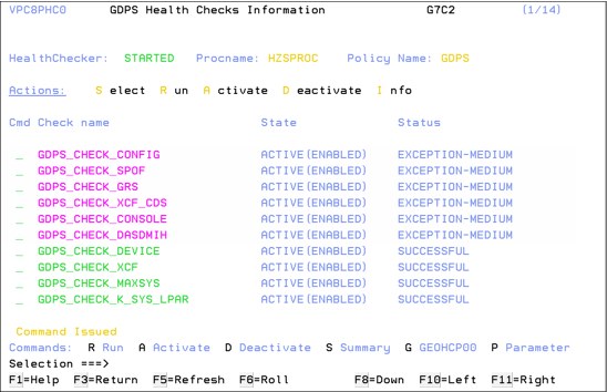
Figure 3-16 GDPS/PPRC Health Check management panel
3.6 Other facilities related to GDPS
In this section we describe miscellaneous facilities provided by GDPS/PPRC that can assist in various ways, such as reducing the window during which disaster recovery capability is not available.
3.6.1 HyperSwap coexistence
In the following sections we discuss the GDPS enhancements that remove some of the restrictions that had existed regarding HyperSwap coexistence with products such as Softek Transparent Data Migration Facility (TDMF) and IMS Extended Recovery Facility (XRF).
HyperSwap and TDMF coexistence
To minimize disruption to production workloads and service levels, many enterprises use TDMF for storage subsystem migrations and other disk relocation activities. The migration process is transparent to the application, and the data is continuously available for read and write activities throughout the migration process.
However, the HyperSwap function is mutually exclusive with software that moves volumes around by switching UCB pointers. The currently supported versions of TDMF and GDPS allow operational coexistence. With this support, TDMF automatically temporarily disables HyperSwap as part of the disk migration process only during the brief time when it switches UCB pointers. Manual operator interaction is not required. Without this support, through operator intervention, HyperSwap is disabled for the entire disk migration, including the lengthy data copy phase.
HyperSwap and IMS XRF coexistence
HyperSwap also has a technical requirement that RESERVEs cannot be allowed in the hardware because the status cannot be reliably propagated by z/OS during the HyperSwap to the new primary volumes. For HyperSwap, all RESERVEs must be converted to GRS global enqueue through the GRS RNL lists.
IMS/XRF is a facility by which IMS can provide one active subsystem for transaction processing, and a backup subsystem that is ready to take over the workload. IMS/XRF issues hardware RESERVE commands during takeover processing and these cannot be converted to global enqueues through GRS RNL processing. This coexistence problem has also been resolved so that GDPS is informed prior to IMS issuing the hardware RESERVE, allowing it to automatically disable HyperSwap. After IMS has finished processing and releases the hardware RESERVE, GDPS is again informed and will re-enable HyperSwap.
3.6.2 Reduced impact initial copy and resynchronization
Performing PPRC copy of a large amount of data across a large number of devices while the same devices are used in production by application workloads can potentially impact production I/O service times if such copy operations are performed synchronously. Your disk subsystems and PPRC link capacity are typically sized for steady state update activity, but not for bulk, synchronous replication. Initial copy of disks and resynchronization of disks are examples of bulk copy operations that can impact production if performed synchronously.
There is no need to perform initial copy or resynchronizations using synchronous copy, because the secondary disks cannot be made consistent until all disks in the configuration have reached duplex state.
GDPS supports initial copy and resynchronization using asynchronous PPRC-XD (also known as Global Copy). When GDPS initiates copy operations in asynchronous copy mode, GDPS monitors progress of the copy operation and when the volumes are near full duplex state, GDPS converts the replication from the asynchronous copy mode to synchronous PPRC. Initial copy or resynchronization using PPRC-XD eliminates the performance impact of synchronous mirroring on production workloads.
Without asynchronous copy it might be necessary to defer these operations or reduce the number of volumes being copied at any given time. This would delay the mirror from reaching a duplex state, thus impacting a client’s ability to recovery. Exploitation of the XD-mode asynchronous copy allows clients to establish or resynchronize mirroring during periods of high production workload, and can potentially reduce the time during which the configuration is exposed.
This function requires that all disk subsystems in the GDPS configuration support PPRC-XD.
3.6.3 Reserve Storage Pool
Reserve Storage Pool (RSP) is a type of resource introduced with z/OS 1.13 zOSMF that can simplify the management of defined but unused volumes. GDPS provides support for including RSP volumes in the PPRC configuration that is managed by GDPS. PPRC primary volumes are expected to be online in Controlling systems, and GDPS monitoring on the GDPS Controlling systems results in an alert being raised for any PPRC primary device that is found to be offline. However, because z/OS does not allow RSP volumes to be brought online to any system, GDPS monitoring recognizes that an offline primary device is an RSP volume and suppresses alerting for these volumes.
3.6.4 Query Services
GDPS maintains configuration information and status information in NetView variables for the various elements of the configuration that it manages. Query Services is a capability that allows client-written NetView REXX programs to query the value for numerous GDPS internal variables. The variables that can be queried pertain to the PPRC configuration, the system and sysplex resources managed by GDPS, and other GDPS facilities such as HyperSwap and GDPS Monitors.
Query Services allows clients to complement GDPS automation with their own automation code. In addition to the Query Services function that is part of the base GDPS product, GDPS provides a number of samples in the GDPS SAMPLIB library to demonstrate how Query Services can be used in client-written code.
GDPS also makes available to clients a sample tool called the Preserve Mirror Tool (PMT), which facilitates adding new disks to the GDPS PPRC configuration and bringing these disks to duplex. The PMT tool, which is provided in source format, makes extensive use of GDPS Query Services and thereby provides clients with an excellent example of how to write programs to benefit from Query Services.
3.6.5 Concurrent Copy cleanup
The DFSMS Concurrent Copy (CC) function uses a “sidefile” that is kept in the disk subsystem cache to maintain a copy of changed tracks that have not yet been copied. For a PPRCed disk, this sidefile is not mirrored to the secondary subsystem. If you perform a HyperSwap while a Concurrent Copy operation is in progress, this will yield unpredictable results. GDPS will not allow a planned swap when a Concurrent Copy session exists against your primary PPRC devices. However, unplanned swaps will still be allowed.
If you plan to exploit HyperSwap for primary disk subsystem failures (unplanned HyperSwap), try to eliminate any use of Concurrent Copy because you cannot plan when a failure will occur. If you choose to run Concurrent Copy operations while enabled for unplanned HyperSwaps, and a swap occurs when a Concurrent Copy operation is in progress, the result will be unpredictable. In the best case scenario, your copy will be invalid and must be recreated. However, because results are unpredictable, there can be other, unforeseen repercussions.
Checking for CC is performed by GDPS immediately prior to performing a planned HyperSwap. SDF trace entries are generated if one or more CC sessions exist, and the swap command will end with no PPRC device pairs being swapped. You must identify and terminate any CC and XRC sessions against the PPRC primary devices prior to the swap.
When attempting to resynchronize your disks, checking is performed to ensure that the secondary devices do not retain CC status from the time when they were primary devices. These are not supported as PPRC secondary devices. Therefore, GDPS will not attempt to establish a duplex pair with secondary devices if it detects a CC session.
GDPS provides a function to discover and terminate Concurrent Copy sessions that would otherwise cause errors during a resync operation. The function is controlled by a keyword that provides options to disable, to conditionally enable, or to unconditionally enable the cleanup of Concurrent Copy sessions on the target disks. This capability eliminates the manual task of identifying and cleaning up orphaned Concurrent Copy sessions prior to resynchronizing a suspended PPRC mirror.
3.7 GDPS/PPRC flexible testing and resync protection
Configuring point-in-time copy (FlashCopy) capacity in your PPRC environment provides two significant benefits:
•It enables you to conduct regular DR drills or other tests using a copy of production data while production continues to run.
•It lets you save a consistent, “golden” copy of the PPRC secondary data, which can be used if the primary disk or site is lost during a PPRC resynchronization operation.
FlashCopy and the various options related to FlashCopy are discussed in 2.6, “FlashCopy” on page 37. GDPS/PPRC supports taking a FlashCopy of either the current primary or the current secondary disks. The COPY, NOCOPY, NOCOPY2COPY, and INCREMENTAL options are supported. Additionally, CONSISTENT FlashCopy is supported in conjunction with COPY, NOCOPY, and INCREMENTAL FlashCopy.
FlashCopy can also be used, for example, to back up data without the need for extended outages to production systems; to provide data for data mining applications; for batch reporting, and so on.
3.7.1 Use of FlashCopy Space Efficient volumes
As discussed in “FlashCopy Space Efficient (FlashCopy SE)” on page 39, by using Space Efficient (SE) volumes, you might be able to lower the amount of physical storage needed and thereby reduce the cost associated with providing a tertiary copy of the data. GDPS provides support allowing FlashCopy Space Efficient volumes to be used as FlashCopy target disk volumes. Whether a target device is Space Efficient or not is transparent to GDPS; if any of the FlashCopy target devices defined to GDPS are Space Efficient volumes, GDPS will simply use them. All GDPS FlashCopy operations with the NOCOPY option, whether through GDPS scripts, panels, or FlashCopies automatically taken by GDPS, can use Space Efficient targets.
Space Efficient volumes are ideally suited to FlashCopy taken for resync protection. The FlashCopy is taken prior to the resync and can be withdrawn as soon as the resync operation is complete. As changed tracks are sent to the secondary for resync, the time zero (T0) copy of this data is moved from the secondary to the FlashCopy target device. This means that the total space requirement for the targets is equal to the number of tracks that were out of sync, which typically will be significantly less than a full set of fully provisioned disks.
Another potential use of Space Efficient volumes is if you want to use the data for limited disaster recovery testing.
Understanding the characteristics of Space Efficient FlashCopy is important to determine whether this method of creating a point-in-time copy will satisfy your business requirements. For example, will it be acceptable to your business if, due to an unexpected workload condition, the repository on the disk subsystem for the Space Efficient devices becomes full and your FlashCopy is invalidated such that you are unable to use it? If your business requirements dictate that the copy must always be guaranteed to be usable, Space Efficient might not be the best option and you can consider using standard FlashCopy instead.
3.8 GDPS tools for GDPS/PPRC
GDPS/PPRC ships tools which provide function that is complementary to GDPS function. The tools represent the kind of function that all or many clients are likely to develop themselves to complement GDPS. Using these tools eliminates the need for you to develop similar function yourself. The tools are provided in source code format which means that if the tool does not exactly meet your requirements, you can modify the code to tailor it to your needs.
The following tools are available with GDPS/PPRC:
•Preserve Mirror Tool (PMT) is intended to simplify and automate, to a great extent, the process of bringing new devices to PPRC duplex state. It also adds these devices to your running GDPS environment while keeping the time during which the GDPS-managed PPRC mirror is not full duplex (and therefore, not protected by Freeze and HyperSwap) to a minimum.
Additionally, PMT provides facilities to aid with migration procedures when using Global Copy (PPRC-XD) and PPRC to migrate data to new disk subsystems.
•Configuration Checker Tool (GEOCHECK) checks whether all devices that are online to a GDPS production system are PPRCed under GDPS control, and raises alerts if violations are encountered. It provides identification and facilitates correction for any production devices that are inadvertently left out of the GDPS-managed PPRC configuration. Not replicating some devices can prevent HyperSwap as well as recovery from catastrophic disk or site failures.
•GDPS Console Interface Tool (GCI) facilitates using the MVS system console as an interface for submitting GDPS scripts for execution or for executing individual script commands. This provides operators who do not have access to the NetView interfaces but do have access to the console with some GDPS operational capability.
•GDPS Distributed Systems Hardware Management Toolkit provides an interface for GDPS to monitor and control distributed systems’ hardware and virtual machines (VMs) by using script procedures that can be integrated into GDPS scripts. This tool provides REXX script templates that show examples of how to monitor/control IBM AIX® HMC; VMware ESX server; IBM BladeCenters; and stand-alone x86 servers with Remote Supervisor Adapter II (RSA) cards. This tool is complementary to the heterogeneous, distributed management capabilities provided by GDPS, such as the Distributed Cluster Management (DCM) and Open LUN management functions.
•GDPS Configuration Assistant (GeoAssistant) Tool helps you to manage the GDPS/PPRC configuration definition file (GEOPARM file). It allows you to create a graphical view of your GEOPARM that can be easily shared and displayed on a variety of devices (such as workstation, tablet, smart phone, and so on). It can analyze and extract various statistics about your configuration. GeoAssistant can also provide step-by-step guidance for coding the GEOPARM statements when adding new devices to an existing configuration
3.9 GDPS/PPRC co-operation with GDPS/Active-Active
GDPS/PPRC provides facilities for co-operation with GDPS/Active-Active if GDPS/Active-Active is used to provide workload level protection for selected workloads that are running on the systems that are in the GDPS/PPRC sysplex. Refer to 7.5, “GDPS/Active-Active co-operation with GDPS/PPRC” on page 205 for details.
3.10 Services component
As you have learned, GDPS touches on much more than simply remote copy. It also includes sysplex, automation, database management and recovery, testing processes, disaster recovery processes, and other areas.
Most installations do not have skills in all these areas readily available. And it is extremely rare to find a team that has this range of skills across many implementations. However, the GDPS/PPRC offering includes exactly that: access to a global team of specialists in all the disciplines you need to ensure a successful GDPS/PPRC implementation.
Specifically, the Services component includes several or all of the following services:
•Planning to determine availability requirements, configuration recommendations, and implementation and testing plans
•Installation and necessary customization of NetView and System Automation
•Remote copy implementation
•Peer-to-Peer VTS implementation
•GDPS/PPRC automation code installation and policy customization
•Assistance in defining Recovery Point and Recovery Time objectives
•Education and training on GDPS/PPRC setup and operations
•Onsite implementation assistance
•Project management and support throughout the engagement
The sizing of the Services component of each project is tailored for that project, based on many factors including what automation is already in place, whether remote copy is already in place, whether the two centers are already in place with a multisite sysplex, and so on. This means that the skills provided are tailored to the specific needs of each particular implementation.
3.11 GDPS/PPRC prerequisites
Refer to the following web site for the latest GDPS/PPRC prerequisite information:
3.12 Comparison of GDPS/PPRC versus other GDPS offerings
There are so many features and functions in the various members of the GDPS family that it is sometimes difficult to recall them all and to remember which offerings support them. To position the offerings, Table 3-1 lists the key features and functions and indicates which ones are delivered by the various GDPS offerings.
Table 3-1 Supported features matrix
|
Feature
|
GDPS/PPRC
|
GDPS/PPRC HM
|
GDPS/XRC
|
GDPS/GM
|
|
Continuous availability
|
Yes
|
Yes
|
No
|
No
|
|
Disaster recovery
|
Yes
|
Yes
|
Yes
|
Yes
|
|
Supported distance
|
200 km
300 km (BRS configuration)
|
200 km
300 km (BRS configuration)
|
Virtually unlimited
|
Virtually unlimited
|
|
FlashCopy support
|
Yes
|
Yes
|
Yes
|
Yes
|
|
Reduced impact initial copy/resynch
|
Yes
|
Yes
|
N/A
|
N/A
|
|
TS7700 support
|
Yes
|
No
|
No
|
No
|
|
PtP VTS support
|
Yes
|
No
|
Yes
|
No
|
|
Production sysplex automation
|
Yes
|
No
|
No
|
No
|
|
Span of control
|
Both sites
|
Both sites
(disk only)
|
Recovery site
|
Disk at both sites.
Recovery site (CBU / LPARs)
|
|
GDPS scripting
|
Yes
|
No
|
Yes
|
Yes
|
|
Monitoring, alerting and health checks
|
Yes
|
Yes
|
Yes
|
Yes
|
|
Query Services
|
Yes
|
Yes
|
Yes
|
Yes
|
|
MGM
|
Yes
(IR or non-IR)
|
Yes
(Non-IR only)
|
N/A
|
Yes
(IR or non-IR)
|
|
MzGM
|
Yes
|
Yes
|
Yes
|
N/A
|
|
Open LUN
|
Yes
|
Yes
|
No
|
Yes
|
|
z/OS equivalent functionality for Linux for System z
|
Yes
|
No
|
Yes
|
Yes
|
|
Heterogeneous support through DCM
|
Yes (VCS and SA AppMan)
|
No
|
Yes (VCS only)
|
Yes (VCS and SA AppMan)
|
|
Web interface
|
Yes
|
Yes
|
No
|
Yes
|
3.13 Summary
GDPS/PPRC is a powerful offering that provides disaster recovery, continuous availability, and system/sysplex resource management capabilities. HyperSwap, available with GDPS/PPRC (or GDPS/PPRC HyperSwap Manager), provides the ability to dynamically swap disks between two sites. The power of automation allows you to test and perfect the actions to be taken, either for planned or unplanned changes, thus minimizing or eliminating the risk of human error.
This is the one offering in the GDPS family that offers the potential of zero data loss, and that can achieve the shortest Recovery Time Objective, typically less than one hour following a complete site failure.
It is also the only member of the GDPS family based on hardware replication that provides the capability to manage the production LPARs. Although GDPS/XRC and GDPS/HM offer LPAR management, their scope for system management only includes the systems in the recovery site, and not the production systems running in Site1.
In addition to the disaster recovery and planned reconfiguration capabilities, GDPS/PPRC also provides a user-friendly interface for monitoring and managing the various elements of the GDPS configuration.
..................Content has been hidden....................
You can't read the all page of ebook, please click here login for view all page.