

GDPS/Active-Active
In this chapter we introduce the GDPS/Active-Active solution. This solution aims to significantly reduce the time taken to recover systems in a disaster recovery situation, and enable planned and unplanned switching of workloads between sites. The chapter includes sections discussing the following aspects of GDPS/Active-Active:
•Concepts
•Products
•Environment
•Functions and features
•Testing
•Services
7.1 Overview of GDPS/Active-Active
In this section we provide a high level description of the GDPS/Active-Active solution and explain where it fits in with the other GDPS products.
7.1.1 Positioning GDPS/Active-Active
The key metrics in business continuity are:
•Recovery Time Objective (RTO) - How long can you afford to be without your systems?
•Recovery Point Objective (RPO) - How much data can you afford to lose or recreate?
•Network Recovery Objective (NRO) - How long does it take to switch over the network?
There are multiple offerings in the GDPS family, all of which are covered in this book. The GDPS products other than GDPS/Active-Active are continuous availability (CA) and disaster recovery (DR) solutions that are based on synchronous or asynchronous disk hardware replication.
To achieve the highest levels of availability and minimize the recovery for planned and unplanned outages, various clients have deployed GDPS/PPRC active/active configurations, which have the following requirements:
•All critical data must be PPRCed and HyperSwap-enabled.
•All critical CF structures must be duplexed.
•Applications must be Parallel Sysplex-enabled.
However, the signal latency between sites will potentially impact online workload throughput and batch duration. This results in sites typically being separated by no more than approximately 20 km fiber distance.1
Consequently, the GDPS/PPRC active/active configuration, which can provide an RPO of zero (0) and an RTO as low as a few minutes, does not provide a solution if an enterprise requires that the distance between the active sites is much greater than 20 to 30 km.
The GDPS products based on asynchronous hardware replication, GDPS/XRC and GDPS/GM, provide for virtually unlimited site separation. However, they do require that the workload from the failed site be restarted in the recovery site and this typically will take 30 to 60 minutes. Thus, GDPS/XRC and GDPS/GM are not able to achieve the RTO of seconds required by various enterprises for their most critical workloads.
In summary, when using the GDPS products based on hardware replication, it is not possible to achieve aggressive RPO and RTO goals while providing the sufficient site separation that is being required by some enterprises.
For these reasons, the Active/Active Sites concept was conceived.
7.1.2 GDPS/Active-Active Sites concept
The Active/Active Sites concept consists of having two sites, separated by virtually unlimited distances, running the same applications and having the same data to provide cross-site workload balancing and continuous availability and disaster recovery. This is a fundamental paradigm shift from a failover model to a continuous availability model.
GDPS/Active-Active (GDPS/A-A) does not use any of the infrastructure-based data replication techniques that other GDPS products rely on, such as Metro Mirror (PPRC), Global Mirror (GM), or z/OS Global Mirror (XRC).
Instead, GDPS/Active-Active relies on both of the following methods:
•Software-based asynchronous replication techniques for copying the data between sites
•Automation, primarily operating at a workload level, to manage the availability of selected workloads and the routing of transactions for these workloads
The GDPS/Active-Active product, which is a component of the GDPS/Active-Active solution, acts primarily as the coordination point or controller for these activities. It is a focal point for operating and monitoring the solution and readiness for recovery.
|
Note: For simplicity, in this chapter we refer to both the solution and the product as GDPS/Active-Active. We might also refer to the environment managed by the solution, and the solution itself, as Active-Active.
|
What is a workload
A workload is defined as the aggregation of the following components:
•Software
User-written applications such as COBOL programs, and the middleware runtime environment (for example, CICS regions, InfoSphere Replication Server instances and DB2 subsystems)
•Data
A related set of objects that must preserve transactional consistency and optionally referential integrity constraints (for example, DB2 Tables and IMS Databases)
•Network connectivity
One or more TCP/IP addresses and ports (for example, 10.10.10.1:80)
There are two different workload types supported and managed in a GDPS/Active-Active environment. These are:
•Update or read/write workloads — these run in what is known as the active/standby configuration. In this case, a workload managed by GDPS/Active-Active will be active in one sysplex and receiving transactions routed to it by the workload distribution mechanism that is managed by the IBM Multi-site Workload Lifeline. The workload will also be using software replication to copy changed data to another instance of the workload running in a second sysplex, where all the infrastructure components (LPARs, systems, middleware and so on) and even the application are ready to receive work in what is termed a standby mode. The updated data from the active instance of the workload is applied in real time to the database subsystem instance running in standby mode.
•Query or read-only workloads — these workloads are associated with update workloads, but they can be actively running in both sites at the same time. Workload distribution between the sites is based on policy options, and takes into account environmental factors such as the latency for replication that determines the age (or currency) of the data in the standby site. There is no data replication associated with the query workload as there are no updates to the data. You can associate up to two query workloads with a single update workload.
Figure 7-1 shows these concepts for an update workload at a high level (not all redundant components are shown in detail). Transactions arrive at the workload distributor, also known as the load balancer. Depending on the current situation, the transactions are routed to what is termed the currently active sysplex in the configuration for that particular workload.
The environment is constantly being monitored to ensure that workload is being processed in the active sysplex. If GDPS/Active-Active detects that workload is not processing normally, then a policy-based decision is made to either automatically start routing work to the standby sysplex (rather than the currently active sysplex), or to prompt the operator to take some action. In a similar way, for query workloads, a policy using the latency of replication as thresholds that will trigger GDPS/Active-Active or other products in the solution to take some action.
Information is constantly being exchanged by the systems in the active and standby sysplexes, the GDPS controllers (one in each location), and the workload distribution mechanism to ensure that an accurate picture of the health of the environment is maintained to enable appropriate decisions from the automation.
It is also possible, in a planned manner, to switch each workload from the currently active to the standby sysplex if the need arises, such as for routine maintenance and so on.
|
Note: In this chapter we might refer to workloads managed by GDPS/Active-Active as Active-Active workloads.
|

Figure 7-1 GDPS/Active-Active concept
In your environment you are likely to have some applications and data which you do not wish to manage with or simply can not be managed by GDPS/Active-Active. For example, you may have an application that uses a data type for which software data replication is not available or is not supported by GDPS/Active-Active. You will still need to provide high availability and disaster recovery for such applications and data. For this, GDPS/Active-Active provides for integration and co-operation with other GDPS products which rely on hardware replication and are independent of application and data type. Specifically, special co-ordination is provided with GDPS/PPRC which we describe in 7.5, “GDPS/Active-Active co-operation with GDPS/PPRC” on page 205 and GDPS/MGM which we describe in 7.6, “GDPS/Active-Active disk replication integration” on page 207.
7.2 GDPS/Active-Active solution products
The GDPS/Active-Active architecture, shown at a conceptual level in Figure 7-2, consists of a number of products coordinating the monitoring and managing of the various aspects of the environment.

Figure 7-2 GDPS/Active-Active architecture
This section describes, at a high level, the various products required for GDPS/Active-Active and their role or function within the overall framework. The following products are briefly discussed:
•GDPS/Active-Active
•IBM Tivoli NetView for z/OS
– IBM Tivoli NetView for z/OS Enterprise Management Agent (NetView agent)
•IBM Tivoli NetView Monitoring for GDPS
•IBM Tivoli Monitoring
•IBM Tivoli System Automation for z/OS
•IBM Multi-site Workload Lifeline for z/OS
•Middleware such as CICS, IMS, DB2, CPSM to run the workloads
•Replication Software
– IBM InfoSphere Data Replication for DB2 for z/OS
• Websphere MQ is required for DB2 data replication
– IBM InfoSphere Data Replication for VSAM for z/OS
• CICS Transaction Server and/or CICS VSAM Recovery are required for VSAM replication
– IBM InfoSphere IMS Replication for z/OS
•Other optional components
– IBM Tivoli OMEGAMON® XE family of monitoring products for monitoring the various parts of the solution
In 7.3, “GDPS/Active-Active environment” on page 182, we provide a solution view that illustrates how the products are used in the various systems in which they run.
7.2.1 The GDPS/Active-Active product
The GDPS/Active-Active product provides automation code that is an extension of many of the techniques that have been tried and tested in other GDPS products and with many client environments around the world for management of their mainframe continuous availability and disaster recovery requirements. The GDPS/Active-Active control code only runs on the Controller systems in the Active-Active environment.
The key functions provided by GDPS/Active-Active code are as follows:
•Workload management, such as starting or stopping all components of a workload in a given sysplex.
•Replication management, such as starting or stopping replication for a given workload from one sysplex to the other.
•Routing management, such as stopping or starting routing of transactions to one sysplex or the other for a given workload.
•System and Server management, such as STOP (graceful shutdown) of a system, LOAD, RESET, ACTIVATE, DEACTIVATE the LPAR for a system and capacity on demand actions such as CBU/OOCoD activation.
•Monitoring the environment and alerting for unexpected situations.
•Planned/Unplanned situation management and control, such as planned or unplanned site or workload switches.
– Autonomic actions, such as automatic workload switch (policy-dependent).
•Powerful scripting capability for complex/compound scenario automation.
•Co-operation with GDPS/PPRC to provide continuos data availability in the Active-Active sysplexes.
•Single point of control for managing disk replication functions when running GDPS/MGM together with GDPS/Active-Active to protect non Active-Active data.
•Easy-to-use graphical user interface.
7.2.2 Tivoli NetView for z/OS
The NetView product is a prerequisite for GDPS/Active-Active automation and management code. In addition to being the operating environment for GDPS, the NetView product provides additional monitoring and automation functions associated with the GDPS/Active-Active solution.
Monitoring capability using the NetView agent is provided for:
•IBM Multi-site Workload Lifeline for z/OS
•IBM InfoSphere Data Replication for DB2 for z/OS
•IBM InfoSphere Data Replication for VSAM for z/OS
•IBM InfoSphere Data Replication for IMS for z/OS
NetView Agent
The Tivoli NetView for z/OS Enterprise Management Agent (also known as TEMA) is used in the solution to pass information from the z/OS NetView environment to the Tivoli Enterprise Portal, which is used to provide a view of your enterprise from which you can drill down to more closely examine components of each system being monitored. The NetView agent requires IBM Tivoli Monitoring.
7.2.3 IBM Tivoli Monitoring
IBM Tivoli Monitoring (also known as ITM) is a suite of monitoring components to monitor and report on various aspects of a client’s IT environment. Several of the IBM Tivoli Monitoring components are used in the overall monitoring of aspects (such as monitoring the workload) within the GDPS/Active-Active environment.
The specific components required for GDPS/Active-Active are listed here.
Tivoli Enterprise Portal
Tivoli Enterprise Portal (portal client or portal, also known as TEP) is a Java-based interface for viewing and monitoring your enterprise. Tivoli Enterprise Portal offers two modes of operation: desktop and browser.
Tivoli Enterprise Portal Server
The Tivoli Enterprise Portal Server (portal server, also known as TEPS), provides the core presentation layer for retrieval, manipulation, analysis, and pre-formatting of data. The portal server retrieves data from the hub monitoring server in response to user actions at the portal client, and sends the data back to the portal client for presentation. The portal server also provides presentation information to the portal client so that it can render the user interface views suitably.
Tivoli Enterprise Monitoring Server
The Tivoli Enterprise Monitoring Server (monitoring server, also known as TEMS) is the collection and control point for performance and availability data and alerts received from monitoring agents (for example, the NetView agent). It is also responsible for tracking the online or offline status of monitoring agents.
The portal server communicates with the monitoring server, which in turn controls the remote servers and any monitoring agents that might be connected to it directly.
7.2.4 System Automation for z/OS
IBM Tivoli System Automation for z/OS is a cornerstone of all members of the GDPS family of products. In GDPS/Active-Active it provides the critical policy repository function, in addition to managing the automation of the workload and systems elements. System Automation for z/OS also provides the capability for GDPS to manage and monitor systems in multiple sysplexes.
System Automation for z/OS is required on the Controllers and all production systems running Active-Active workloads. If you use an automation product other than System Automation for z/OS to manage your applications, you do not need to replace your entire automation with System Automation. Your existing automation can coexist with System Automation and an interface is provided to ensure proper coordination takes place.
7.2.5 IBM Multi-site Workload Lifeline for z/OS
This product provides intelligent routing recommendations to external load balancers for server instances that can span two sysplexes/sites. The IBM Multi-site Workload Lifeline for z/OS product consists of Advisors and Agents.
There is one Lifeline Advisor that is active in the same z/OS image as the GDPS Primary Controller and assumes the role of primary Advisor, and at most one other Lifeline Advisor that is active on the Backup Controller and assumes the role of secondary Advisor.
The two Advisors exchange state information such that the secondary Advisor can take over the primary Advisor role in the event that the current primary Advisor is terminated or there is a failure on the system where the primary Advisor was active.
In addition, there is a Lifeline Agent that is active on all z/OS images where workloads can run. All Lifeline Agents monitor the health of the images they are running on, and the health of the workload. These Agents communicate this information back to the primary Lifeline Advisor, which then calculates routing recommendations.
Finally, external load balancers establish a connection with the primary Lifeline Advisor and receive routing recommendations through the open-standard Server/Application State Protocol (SASP) API that is documented in RFC 4678.
The Lifeline Advisor also establishes a Network Management Interface (NMI) to allow network management applications (such as NetView) to retrieve internal data that the Advisor uses to calculate routing recommendations.
The Lifeline Advisors and Agents use configuration information stored in text files to determine what workloads need to be monitored and how to connect to each other and external load balancers.
GDPS/Active-Active provides high level control capabilities to start and stop replication for a given workload to one sysplex/site or the other using either GDPS automation scripts or panel actions in the GDPS GUI.
7.2.6 Middleware
Middleware components such as CICS regions or DB2 subsystems form a fundamental part of the Active/Active environment because they provide the application services required to process the workload. To maximize the availability characteristics of the GDPS/Active-Active environment, applications and middleware need to be replicated across multiple images in the active and standby Parallel Sysplexes to cater for local high availability in case of component failure. Automation needs to be in place to ensure clean startup, shutdown, and local recovery of these critical components. CICS/DB2 workloads managed by CPSM derive additional benefits in a GDPS/Active-Active environment.
7.2.7 Replication software
Unlike in other GDPS solutions where the replication is based on mirroring the disk-based data at the block level using hardware (such as Metro Mirror or Global Mirror) or a combination of hardware and software (z/OS Global Mirror, also known as XRC) as previously mentioned, replication in GDPS/Active-Active is managed by software only. The following products are supported in GDPS/Active-Active:
•IBM InfoSphere Data Replication for DB2 for z/OS
This product, also known widely as Q-rep, uses underlying IBM WebSphere MQ as the transport infrastructure for moving the DB2 data from the source to the target copy of the database. Transaction data is captured at the source site and placed in MQ queues for transmission to a destination queue at the target location, where the updates are then applied in real time to a running copy of the database.
This product, also known widely as Q-rep, uses underlying IBM WebSphere MQ as the transport infrastructure for moving the DB2 data from the source to the target copy of the database. Transaction data is captured at the source site and placed in MQ queues for transmission to a destination queue at the target location, where the updates are then applied in real time to a running copy of the database.
For very large scale and update-intensive DB2 replication environments, a single pair of capture/apply engines may not be able to keep up with the replication. Q-rep provides a facility known as Multiple Consistency Groups (MCG) where the replication work is spread across multiple capture/apply engines, yet the time order (consistency) for the workload across all of the capture/apply engines is preserved in the target database. GDPS supports and provides specific facilities for workloads using MCG with DB2 replication.
•IBM InfoSphere Data Replication for IMS for z/OS
IBM InfoSphere IMS Replication for z/OS is the product that provides IMS data replication and uses a similar capture and apply technique to that outlined for DB2 data. However, IMS Replication does not use MQ as the transport infrastructure to connect the source and target copies. Instead, TCP/IP is used in place of MQ through the specification of host name and port number to identify the target to the source and similarly to define the source to the target.
IBM InfoSphere IMS Replication for z/OS is the product that provides IMS data replication and uses a similar capture and apply technique to that outlined for DB2 data. However, IMS Replication does not use MQ as the transport infrastructure to connect the source and target copies. Instead, TCP/IP is used in place of MQ through the specification of host name and port number to identify the target to the source and similarly to define the source to the target.
•IBM InfoSphere Data Replication for VSAM for z/OS
IBM InfoSphere Data Replication for VSAM for z/OS is very similar in structure to the IMS replication product except that it is for replicating VSAM data. For CICS VSAM data, the source for capture are CICS log streams. For non-CICS VSAM data, CICS VSAM Recovery (CICS VR) is required for logging, and will be the source for replicating such data. Similar to IMS replication, TCP/IP is used as the transport for VSAM replication.
IBM InfoSphere Data Replication for VSAM for z/OS is very similar in structure to the IMS replication product except that it is for replicating VSAM data. For CICS VSAM data, the source for capture are CICS log streams. For non-CICS VSAM data, CICS VSAM Recovery (CICS VR) is required for logging, and will be the source for replicating such data. Similar to IMS replication, TCP/IP is used as the transport for VSAM replication.
GDPS/Active-Active provides high level control capabilities to start and stop replication between identified source and target instances through both scripts and panel actions in the GDPS GUI. Additionally, GDPS monitors replication latency and uses this information when deciding whether Query workloads can be routed to the standby site or not.
7.2.8 Other optional components
Other components can optionally be used to provide specific monitoring, as described here.
Tivoli OMEGAMON XE family
Additional products such as Tivoli OMEGAMON XE on z/OS, Tivoli OMEGAMON XE for DB2, and Tivoli OMEGAMON XE for IMS, can optionally be deployed to provide specific monitoring of products that are part of the Active/Active sites solution.
7.3 GDPS/Active-Active environment
In this section we provide a conceptual view of a GDPS/Active-Active environment, plugging in the products that run on the various systems in the environment. We then take a closer look at how GDPS/Active-Active works. Finally, we briefly discuss environments where Active-Active and other workloads coexist on the same sysplex.
Figure 7-3 shows the key components of a GDPS/Active-Active environment.

Figure 7-3 GDPS/Active-Active environment functional overview
The GDPS/Active-Active environment consists of two production sysplexes (also referred to as sites) in different locations. For each update workload that is to be managed by GDPS/Active-Active, at any given point in time, one of the sysplexes will be the active sysplex and the other will act as standby. In the figure we have one workload and only one active production system running this workload in one sysplex, and one production system that is standby for this workload. However, there can be multiple cloned instances of the active and the standby production systems in the two sysplexes.
When there are multiple workloads managed by GDPS, a given sysplex can be the active sysplex for one update workload, while it is standby for another. It is the routing for each update workload that determines which sysplex is active and which sysplex is standby for a given workload. As such, in environments where there are multiple workloads, there is no concept as an active sysplex. There is a sysplex that is the currently active one for a given update workload.
The production systems, both the active and the standby instances are actively running the workload managed by GDPS. What makes a sysplex (and therefore the systems in that sysplex) active or standby is whether update transactions are currently being routed to that sysplex. The SASP routers in the network, which are shown in the figure as the cloud under GDPS and LifeLine Advisor, control routing of transactions for a given workload to one sysplex or the other. Although a single router is the minimum requirement, we expect that you will configure multiple routers for resiliency.
The workload is actively running on the z/OS system in both sysplexes. The workload on the system that is active for that workload is actually processing update transactions because update transactions are being routed to this sysplex.
The workload on the standby sysplex is actively running but is not processing any update transactions because update transactions are not being routed to it. It is waiting for work, and is able to process work at any time if there is a planned or unplanned workload switch resulting in transactions being routed to this sysplex. If there is a workload switch, the standby sysplex will become the active sysplex for the given workload.
The workload on the standby sysplex can be actively processing query transactions for the query workload that is associated with an update workload. Replication latency at any given point in time, in conjunction with thresholds you specify in the GDPS policy, determines whether query transactions are routed to the standby sysplex or not. The GDPS policy indicates when the latency or the replication lag is considered to be too high (that is, the data in the standby sysplex is considered to be too far behind) to the extent that query transactions should no longer be routed there, but should be routed to the active sysplex instead. When query transactions are no longer being routed to the standby sysplex because the latency threshold was exceeded, there is another threshold that you specify in the GDPS policy which indicates when it is OK to route query transactions to the standby sysplex once again.
For example, your policy might indicate that query transactions for a given workload should not be routed to the standby sysplex if latency exceeds 7 seconds and that it is OK to route to the standby sysplex once latency falls below 4 seconds. Latency is continually monitored to understand whether query transactions can be routed to the standby sysplex or not. In addition to the latency control, you can specify a policy to indicate what percentage of the incoming query transactions should be routed to the standby site or whether you simply want the conditions such as latency and workload health to dictate a dynamic decision on which of the two sysplexes query transactions would be routed to at any given point in time.
The workload itself is any subsystem receiving and processing update and or query transactions through the routing mechanism and using the replicated databases.
On the active system, you see that there is a replication capture engine. There can be one or more such engines, depending on the data being replicated. This is the software replication component that captures all updates to the databases used by the workload managed by GDPS and forwards them to the standby sysplex.
On the standby sysplex there is the counterpart of the capture engine, which is the apply engine. The apply engine receives the updates sent by the capture engine and immediately applies them to the database for the standby sysplex. The data replication in a GDPS environment is asynchronous. This means that the workload can perform a database update and this write operation can complete, independent of the replication process. Replication will require sufficient bandwidth for transmission of the data being replicated. IBM has services that can help you determine the bandwidth requirements based on your workload. If replication is disrupted for any reason, the replication engines, when restored, have logic to know where they left off and are able to transmit only those changes made after the disruption.
Because the replication is asynchronous, there is no performance impact associated with replication. For a planned workload switch, the switch can take place after all updates are drained from the sending side and applied on the receiving side. For DB2 replication, GDPS provides additional automation in order to understand whether all updates have drained. This allows planned switch of workloads using DB2 replication to be completely automated.
For an unplanned switch, because replication is asynchronous, there will typically be some data captured but not yet transmitted and therefore not yet applied on the target sysplex. The amount of this data effectively translates to RPO. With a correctly-sized, robust transmission network, the RPO, during normal operations, is expected to be as low as just a few seconds. You might also hear the term latency used in conjunction with replication. Latency is simply another term that is used for the replication lag or RPO.
Although we talk about RPO, data is only lost if the original active site or the disks in this site where some updates were stranded are physically damaged such that they can not be restored with the data intact. Following an unplanned switch to the standby site, if the former active site is restored with its data intact, any stranded updates can be replicated to the new active site at that time and no data will have been lost.
MQ is shown on production systems. MQ is required for DB2 replication. Either CICS or CICS VR is required on the production systems for VSAM replication.
On the production systems on both the active and standby sysplexes, you will also see the monitoring and management products. NetView, System Automation and the LifeLine Agent run on all production systems, monitoring the system, the workload on the system as well as replication latency and providing information to the Active-Active Controllers.
TCP/IP on the production systems is required in support of a number of functions related to GDPS/Active-Active.
Finally, on the production systems we show that you might have a product other than System Automation to manage your applications. In such an environment, as previously described, System Automation is still required for GDPS/Active-Active workload management. However, it is not necessary to replace your existing automation to use System Automation. A simple process for enabling the coexistence of System Automation and other automation products is available.
Not shown in Figure 7-3 on page 182 is the possibility of running other workloads not managed by GDPS/Active-Active on the same production systems that run Active-Active workloads. We discuss other, non-Active-Active workloads in 7.3.2, “Considerations for other non-Active-Active workloads” on page 188.
Figure 7-3 on page 182 shows two GDPS Controller systems. At any point in time, one is the Primary Controller and the other is the Backup. These will typically be in each of the production sysplex locations, but there is no requirement that they are co-located in this way. GDPS/Active-Active introduces the term Controller, as opposed to the Controlling System term used within other GDPS solutions. The function of the Primary Controller is to provide a point of control for the systems and workloads participating in the GDPS/Active-Active environment for both planned actions (such as IPL and directing which is the active sysplex for a given workload) and for recovery from unplanned outages. The Primary Controller is also where the data collected by the monitoring aspects of the solution can be accessed.
Both Controllers run NetView, System Automation and GDPS/Active-Active control code, and the LifeLine Advisor. The Tivoli Monitoring components Tivoli Enterprise Monitoring Server and Tivoli Enterprise Management Agent run on the Controllers. Figure 7-3 on page 182 shows that there is a portion of Tivoli Monitoring not running on z/OS. The Tivoli Enterprise Portal Server component can run either on Linux on System z or on a distributed server.
Together with System Automation on the Controllers you see the BCP Internal Interface (BCPii). GDPS, on the Controller, uses this interface to perform hardware actions against the LPAR of production systems or the LPAR of the other Controller system such as LOAD, RESET, and so on, and for performing hardware actions for capacity on demand such as CBU or OOCoD activation.
The figure also shows the Support Element/Hardware Management Console (SE/HMC) Local Area Network (LAN). This is a key element of the GDPS/Active-Active solution. The SE/HMC LAN spans the System z servers for both sysplexes in the two sites. This allows for a Controller in one site to act on hardware resources in the other site. To provide a LAN over large distance, the SE/HMC LANs in each site are bridged over the WAN.
It is desirable to isolate the SE/HMC LAN on a network other than the client’s WAN, which is the network used for the Active-Active application environment and connecting systems to each other. When isolated on a separate network, Lifeline Advisor (which is responsible for detecting failures and determining whether a sysplex has failed altogether or not) can try to access the site that appears to have failed over the both over the WAN and the SE/HMC LAN.
If the site is accessible through the SE/HMC LAN but not the WAN, then Lifeline can conclude that only the WAN failed, and not the target sysplex. Thus, isolating the SE/HMC LAN from the WAN provides an additional check when deciding whether the entire sysplex has failed and therefore whether or not a workload switch is to be performed.
7.3.1 GDPS/Active-Active - a deeper dive
We have already discussed how GDPS/Active-Active works at a conceptual level, and have seen how the various products that comprise the solution fit into the Active-Active framework.
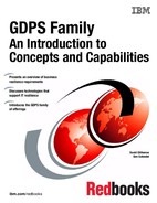
In this section we take a closer look at how GDPS/Active-Active works, using an example of a GDPS/Active-Active environment with multiple workloads; see Figure 7-4. In this example we are only considering update workloads. It would be a simple matter to extend this example with query workloads corresponding to one or more of the update workloads.
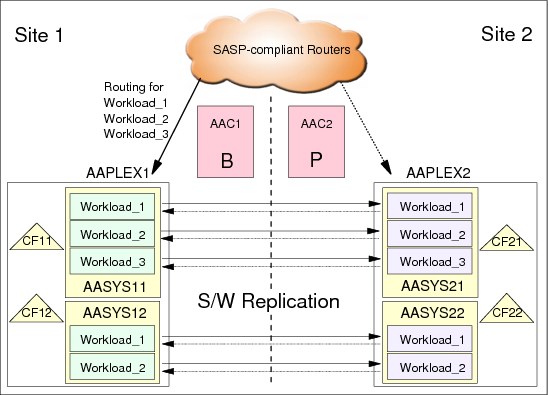
Figure 7-4 GDPS/Active-Active environment with multiple workloads - all active in one site
The figure shows there are two sites, Site1 and Site2, and there is a Parallel Sysplex in each site: AAPLEX1 runs in Site1 and AAPLEX2 runs in Site2. Coupling facilities CF11 and CF12 serve AAPLEX1 structures. CF21 and CF22 serve AAPLEX2 structures.
Each sysplex consists of two z/OS images. The z/OS images in AAPLEX1 are named AASYS11 and AASYS12. The images in AAPLEX2 are named AASYS21 and AASYS22. Additionally, there are two GDPS Controller systems: AAC1 is in Site1, and AAC2 is in Site2.
There are three workloads managed by GDPS in this environment: Workload_1, Workload_2, and Workload_3. As you can see, Workload_1 and Workload_2 are cloned, Parallel Sysplex-enabled applications that run on both z/OS images of the sysplexes. Workload_3 runs only in a single image in the two sysplexes.
At this time, the transactions for all three workloads are being routed to AAPLEX1. The workloads are running in AAPLEX2, but they are not processing transactions because no transactions are being routed to AAPLEX2.
AAPLEX1 is the source for data replication for all three workloads, and AAPLEX2 is the target. Also shown are reverse replication links from AAPLEX2 towards AAPLEX1. This indicates that if the workload is switched, the direction of replication can and will be switched.
If AASYS12 incurs an unplanned z/OS outage, then all three workloads would continue to run in AASYS11. It is possible, depending on the sizing of the systems, that AASYS11 does not have sufficient capacity to run the entire workload. Additionally, AASYS11 is now a single point of failure for all three workloads. In such a case, where no workload has failed but there is a possible degradation of performance and availability levels, you need to decide whether you want to continue running all three workloads in AASYS11 until AASYS12 can be restarted or whether you switch one or more (or possibly all three) workloads to run in AAPLEX2 systems. These are decisions you will prepare in advance, that is, a so-called, pre-planned unplanned scenario.
If you decide to switch one or more workloads to run actively in AAPLEX2, you will typically use a pre-coded planned action GDPS script to perform the switch of the desired workloads. Switching a workload in this case requires the following actions, all of which can be performed in a single script:
•Stop the routing of transactions for the selected workloads to AAPLEX1
•Wait until all updates for the selected workloads on AAPLEX1 are replicated to AAPLEX2
•Stop replication for the selected workloads from AAPLEX1 to AAPLEX2
•Start replication for the selected workloads from AAPLEX2 to AAPLEX1
•Start the routing of transactions for the selected workloads to AAPLEX2
Such a planned action script, after it is initiated, can complete the requested switching of the workloads in a matter of seconds.
As you can see, we do not stop the selected workloads in AAPLEX1. There is no need to stop the workload for this particular scenario where we simply toggled the subject workloads to the other site to temporarily provide more capacity and/or remove a temporary single point of failure. We did assume in this case that AAPLEX2 had sufficient capacity available to run the workloads being switched. If AAPLEX2 did not have sufficient capacity, GDPS can have additionally activated On/Off Capacity on Demand (OOCoD) on one or more servers in Site2 running the AAPLEX2 systems prior to routing transactions there.
Now assume that you decided to switch Workload_2 to Site2 but you keep Site1/AAPLEX1 as the primary for the other two workloads. When the switch is complete, the position you will end up with is depicted in Figure 7-5. In this picture, we assume that you have also restarted in place the failed image, AASYS12.

Figure 7-5 GDPS/Active-Active environment with different workloads active in different sites
The router cloud shows to which site the transactions for each of the workloads is being routed. Based on routing, AAPLEX2 is now the active sysplex for Workload_2. AAPLEX1 remains the active sysplex for Workload_1 and Workload_3. Replication for the data for Workload_2 is from AAPLEX2 to AAPLEX1. Replication for the other two workloads is still from AAPLEX1 to AAPLEX2. You might hear the term dual active/active being used to describe this kind of an environment where both sites/sysplexes are actively running different workloads, but each workload is active/standby.
The example we discussed was an outage of AASYS12 that runs only cloned instances of the applications for Workload_1 and Workload_2. In contrast, Workload_3 has no cloned instances and only runs on AASYS11. An unplanned outage of AASYS11 will result in an actual failure of Workload_3 in its current sysplex. This is a failure that is detected and, based on your workload failure policy, can trigger an automatic switch of the failed workload to the sysplex that is standby for that workload.
However, if you do not want GDPS to perform automatic workload switch for failed workloads, you can select the option of an operator prompt. The operator is prompted as to whether GDPS is to switch the failed workload or not. If the operator accepts switching of the workload, then GDPS will perform the necessary actions to switch the workload. For this kind of switch resulting from a workload failure, whether automatic or operator confirmed, no pre-coded scripts are necessary. GDPS understands the environment and performs all the required actions to switch the workload.
In this particular example, all components of Workload_3 were already running in AAPLEX2 and were ready to receive transactions. If Workload_3 was not running at the time a switch is triggered, then GDPS cannot perform the switch. In this case, the operator is notified that the standby sysplex is not ready to accept transactions for the given workload. The operator can now fix whatever is missing (for example, the operator can use the GDPS GUI to start the subject workload in the target sysplex) and then respond to the prompt, allowing GDPS to proceed with the switch.
Continuing with the same example where AASYS11 has failed, resulting in failure of Workload_3 in AAPLEX1, when GDPS performs the workload switch, then AAPLEX2 becomes the active sysplex and AAPLEX1 should be the standby. However, AAPLEX1 can only serve as standby when AASYS11 is restarted and Workload_3 is started on it.
Additionally, in the meanwhile, transactions are running in AAPLEX2 and updating the data for Workload_3. Until replication components of Workload_3 are restarted in AAPLEX1, the updates are not replicated from AAPLEX2 to AAPLEX1. When replication components are restored on AAPLEX1, replication must be started for Workload_3 from AAPLEX2 to AAPLEX1. The replication components for Workload_3 on AAPLEX1 will now resynchronize, and the delta updates that occurred while replication was down will be sent across. When this is complete, AAPLEX1 can be considered to be ready as the standby sysplex for Workload_3.
For an entire site/sysplex failure, GDPS provides similar capabilities as those for individual workload failure. In this particular case, multiple workloads might be affected. Similar to workload failure, there is policy that determines whether GDPS is to automatically switch workloads that fail as a result of a site failure or perform a prompted switch. The only difference here is that the policy is for workloads that fail as a result of an entire site failure whereas in the previous example, we discussed the policy for individual workload failure. For each workload you can specify individually whether GDPS is to perform an automatic switch or prompt the operator. Furthermore, for each workload you can select a different option (automatic or prompt) for individual workload failure versus site failure.
For entire site/sysplex failures where multiple workloads are affected and switched, GDPS provides parallelization. This means that the RTO for switching multiple workloads is much the same as switching a single workload. Unplanned workload switches are expected to take slightly longer than planned switches. This is because GDPS must wait an amount of time to make sure that the unresponsive condition of the systems/workloads is not due to a temporary stall that can soon clear itself (that is, a false alarm). This is a safety mechanism very similar to the failure detection interval for systems running in a sysplex where in the Active-Active case, the aim is to avoid unnecessary switches due to a false alert. However, after the failure detection interval expires and the systems/workloads continue to be unresponsive, the workload switches are very fast and as mentioned earlier, are performed in parallel for all workloads being switched.
In summary, GDPS/Active-Active manages individual workloads. Different workloads can be active in different sites. What is not allowed is for a particular workload to be actively receiving and running transactions in more than one site at any given point in time.
7.3.2 Considerations for other non-Active-Active workloads
In the same sysplex where Active-Active workloads are running, you might have other workloads that are not managed by GDPS/Active-Active.
In such an environment, where Active-Active and non-Active-Active workloads coexist, it is important to provide the necessary level of isolation for the Active-Active workloads and data. The data belonging to the Active-Active workloads is replicated under GDPS/Active-Active control and must not be used by non-managed applications.
So, assume you have a workload active in Site1 and standby in Site2. And assume you have a non-managed application in Site1 that uses the same data that is used by your managed workload. If you now switch your managed workload to Site2, the non-managed workload that is not included in the Active-Active solution scope will continue to update the data in Site1 while the managed workload has started to update the database instance in Site2. Such use of data belonging to Active-Active workloads by non-managed applications can result in data loss, potential data corruption, and serious operational issues.
For this reason, the data belonging to Active-Active workloads must not be used by other applications. The simplest way to provide this isolation is to run Active-Active workloads and other workloads in different sysplexes.
We understand that it might not be easy or possible to provide sysplex-level isolation. In this case, if you have isolated the Active-Active workloads and data, you might have other non-managed workloads and the data for such workloads coexisting in the same sysplex with Active-Active. However, another technique (in addition to GDPS/Active-Active for the Active-Active workloads), perhaps hardware replication together with a solution such as GDPS/PPRC, GDPS/GM, or GDPS/XRC, needs to be employed to protect the data and to manage the recovery process for the non-Active-Active workloads.
GDPS/Active-Active has specific function in order to cooperate and coordinate actions with GDPS/PPRC running on the same sysplex. GDPS/PPRC can protect the entire sysplex, not just the systems running the Active-Active workloads. Refer to 7.5, “GDPS/Active-Active co-operation with GDPS/PPRC” on page 205 for a more detailed description of this capability.
GDPS/Active-Active also provides for integration of disk replication functions for a GDPS/MGM configuration such that the GDPS/Active-Active Controllers can act as a single point of management and control for both GDPS/Active-Active workloads and GDPS/MGM replication. All data for all systems, for both Active-Active and non Active-Active workloads, can be covered with GDPS/MGM. 7.6, “GDPS/Active-Active disk replication integration” on page 207 provides a high level overview of this facility.
Because client environments and requirements vary, there is no “one size fits all” type of recommendation that we can make here. Suffice it to say that it is possible to combine GDPS/Active-Active with various other hardware-replication-based GDPS products to provide a total recovery solution for a sysplex that houses both Active-Active and other workloads. If you are unable to isolate your Active-Active workloads into a separate sysplex, discuss this with your IBM GDPS specialist, who can provide you with guidance based on your specific environment and requirements.
7.4 GDPS/Active-Active functions and features
In this section we provide a brief overview of the functions and capabilities provided by the GDPS/Active-Active product. These are:
•GDPS web graphical user interface
•Standard Actions for system/hardware automation
•Monitoring and Alerting
•GDPS scripts
•GDPS Query Services
7.4.1 GDPS/Active-Active web interface
GDPS/Active-Active is operated on the Controller systems using an operator interface provided through a web-based browser session. The interface is intuitive and easy to use. Unlike other predecessor GDPS products, there is no 3270-based user interface available with GDPS/Active-Active.
The web interface display, as shown in Figure 7-6, has three sections:
•A portfolio or menu bar on the left with links to the main GDPS options.
• A window list on top allowing switching between multiple open frames.
• An active task frame (work area) where the relevant information is displayed and activities are performed for a selected option. The active task frame for different tasks are designed to have a common “look and feel” to the layout.
Nearly all frames have a Help button to provide extensive help text associated with the information displayed and the selections available on that specific frame.
|
Note: Some panels provided as samples may not be the very latest version of the panel. They are intended to give you an idea of the capabilities available using the web interface.
|

Figure 7-6 GDPS User Interface - initial panel
Controllers panels and functions
When an operator accesses the GDPS/Active-Active web interface, the initial panel that is displayed is the “Controllers” panel; see Figure 7-6. This panel identifies the Controller systems for this GDPS/Active-Active environment. In this example they are the systems named G4C1 (NetView Domain ID A6P41), which is the Primary Controller (or the Master) system, and G5C1 (NetView Domain ID A6P51), which is the Backup Controller.
On the top of the menu bar on the left you can see that the operator is currently logged on to the Controller system with domain ID of A6P41, which happens to be the Primary Controller. In this position, the operator can only perform actions such as STOP which is a graceful shutdown, LOAD or RESET the LPAR, and so on, against the other Controller. GDPS does not allow disruptive actions to be performed against the system that the operator is logged onto.
At the bottom of the frame you see a grayed-out Change MASTER button. This button, when selectable (it is only selectable when you are logged on to the Backup Controller), allows you to make the current Backup Controller the new Master Controller; that is, it allows you to perform a Controller switch.
GDPS Standard Actions
Because the operator is normally logged on to the Primary Controller, the operator will only be allowed to perform actions against the Backup Controller. When the Backup Controller is selected, the frame shown in Figure 7-7 is displayed. On this frame you see that GDPS Standard Actions can be performed against the other Controller system, which in this case is the Backup Controller.

Figure 7-7 Web interface frame with GDPS Standard Actions buttons
Figure 7-7 shows the following GDPS Standard Actions that can be performed against the selected target system, available as buttons in the frame:
•LOAD
•STOP (graceful shutdown)
•RESET
•Activate LPAR
•Deactivate LPAR
•Modification and selection of Load Address and Load Parameters to be used during a subsequent LOAD operation
Most of the GDPS Standard Actions require actions to be carried out on the HMC. The interface between GDPS and the HMC is through the BCP Internal Interface (BCPii). GDPS uses the BCPii interface provided by System Automation for z/OS.
When a specific Standard Action is selected by clicking the button for that action, there are further prompts and windows for operator action such as confirming that they really want to perform the subject operation.
Although in this example we have shown using GDPS Standard Actions to perform operations against the other Controller, in an Active-Active environment, you will also use the same set of Standard Actions to operate against production systems in the environment.
If certain actions are performed as part of a compound workflow (such as planned shutdown of an entire site where multiple systems will be stopped, the LPARs for multiple systems RESET and Deactivated, and so on), then the operator will typically not use the web interface but instead perform the same actions through the GDPS scripting interface. GDPS scripts are discussed in detail in 7.4.3, “GDPS/Active-Active scripts” on page 200.
The GDPS LOAD and RESET Standard Actions (available via the Standard Actions panel or the SYSPLEX script statement) allow specification of a CLEAR or NOCLEAR operand. This provides operational flexibility in order to accommodate customer procedures, eliminating the requirement to use the HMC to perform specific LOAD and RESET actions.
GDPS provides support for taking a Stand-Alone Dump using the GDPS Standard Actions panel. The Stand-Alone Dump can be used against any System z operating system defined to GDPS. Customers using GDPS facilities to perform HMC actions no longer need to use the HMC for taking Stand-Alone Dumps.
Sites panels and functions
The Sites task, when selected from the menu on the left side on every web interface frame, allows you to perform GDPS Standard Actions against the production systems within your GDPS/Active-Active environment. Two examples of the frame displayed when you select this task are shown in Figure 7-8. As shown, the information provides a view of the status of the systems within the sites. The upper panel in the display shows normal status, with all systems active. The lower panel gives clear indication of a problem in Site G5, where neither of the two expected systems are active.

Figure 7-8 Sites frame
Essentially, apart from the standard header information, this panel allows you to select which of the sites you want to interact with. You simply click the site name. Figure 7-9 shows the frame displayed when, in our example, G4 is selected.

Figure 7-9 Sites frame for site/sysplex G4 selected
You can then select the specific system you want to use as a target for a GDPS Standard Actions operation. Performing Standard Actions, such as STOP, LOAD, RESET and so on against a production system is identical to performing such actions against a Controller as shown on Figure 7-7 on page 191 and described in “GDPS Standard Actions” on page 191.
Workload Management panels and functions
The Workload Management task, selected from the menu bar, displays the Workload Management frame. An example of this frame is shown in Figure 7-10. This frame shows and provides “at a glance” high level status summary information for all workloads, update and query, that are defined for this GDPS environment.

Figure 7-10 Workload Management frame
The status shown in each of the sites is based on information from GDPS Monitoring and from System Automation running in the production systems in that site.
You can click any of the workload names to select the details frame for that workload. An example of this Workload details frame is shown in Figure 7-11 on page 195.
The Workload details frame allows you to perform the following operations against the selected workload such as Start/Stop of the workload or Start/Stop of routing for that workload to one site or the other.
In addition to these operations, the frame provides further status detail associated with the selected workload.

Figure 7-11 Workload details frame
Similar to Standard Actions, there are GDPS script statements that perform these same operations and typically, a script is used to perform these actions and Standard Actions for a compound/complex scenario such as an entire site shutdown. See 7.4.3, “GDPS/Active-Active scripts” on page 200 for details about using the GDPS scripting capability.
Planned Actions panels and functions
GDPS Planned Actions are initiated from the Planned Actions frame within the GDPS user interface. When you select the Planned Actions task from the menu bar, you see a Planned Actions frame similar to that shown in Figure 7-12 on page 196.
Planned Actions allows you to view and execute scripts for planned scenarios such as site shutdown, site startup, or CEC shutdown and startup. You are presented with a list of scripts that you have already coded, anticipating a given planned scenario. Along with the name of the script, you are also presented with a comment that describes what a given script is intended for. You can then select a script for viewing and execution on this panel.

Figure 7-12 Sample Planned Actions frame
When you select a script from the list, you are presented with a panel that displays the actual script content as shown in Figure 7-13. On this panel, after you view the actual script content, you can execute it. If you have selected the wrong script, you can return.

Figure 7-13 Planned Action script example
Launching Tivoli Enterprise Portal from the GDPS web interface
You can use the Launch TEP link on the menu bar to view information available through the Tivoli Enterprise Portal (TEP). TEP provides views and levels of detail pertaining to the GDPS/Active-Active environment other than what is available through the GDPS web interface. Hence, when investigating a problem (for example, due to an alert that is raised in GDPS), it can be quite useful to simply launch TEP directly from the GDPS web interface and drill down into the views of your environment that are available through TEP.
After TEP is launched, you can drill down to Active-Active frames to view details pertaining to the Active-Active Load Balancers, Replication Servers, Workload Lifeline Advisors, and Workloads. Figure 7-14 shows TEP views of Replication Servers. The bottom portion of the figure contains summary information for the replicator associated with each of the workloads managed by GDPS/Active-Active. The graph on the top provides details about the breakdown of latency for each of the replicators in the environment.

Figure 7-14 Launch TEP - Replication Servers frame
The Tivoli Enterprise Portal, in addition to providing a monitoring interface to the overall solution, allows you to set up specific situations for alerting of conditions such as the replication latency exceeding a certain threshold. The workload-related workspaces can also show quickly such things as the number of servers active in both sites and where the routing is active to. This information can be useful to correlate against that shown in the GDPS web interface to confirm the status of any particular resources.
Other web interface options
There are other options available to the operator through the web interface.
Status Display Facility
Status Display Facility (SDF) is the focal point for monitoring the GDPS/Active-Active environment. A link to SDF is available on the top portion of every web interface frame. SDF is a very important component of GDPS and is discussed in detail under 7.4.2, “GDPS/Active-Active monitoring and alerting” on page 198.
WTORs
Similar to SDF, the WTORs function is selectable on the top portion of every web interface frame. The WTORs function opens a new window to display any Write to Operator with Reply (WTOR) messages that are outstanding and provides the option to reply to any selected message.
Turning Debug ON/OFF
As a NetView-based automation application, GDPS/Active-Active uses the NetView log as the main repository for information logging. In addition to the NetView log, selected critical GDPS messages are also sent to the z/OS system log.
The GDPS Debug facility enables logging in the NetView log, providing more detailed trace entries pertaining to the operations that GDPS is performing. If you encounter a problem, you might want to collect debug information for problem determination purposes. If directed by IBM support, you might need to trace execution of specific modules. The GDPS debug facility also allows you to select the modules to be traced. The Debug frame is presented when you select Debug On/Off task on the menu bar.
View definitions
The view definitions option, also selected through the menu bar, allows you to view the various definitions and options related to GDPS that are in effect. The bulk of the GDPS definitions are made in the System Automation policy database. If you modify some of these definitions or for any other reason want to check what definitions GDPS is using, you can use this facility.
7.4.2 GDPS/Active-Active monitoring and alerting
GDPS/Active-Active Controller systems perform periodic monitoring of resources and conditions that are critical or important for the healthy operation of the environment. For example, GDPS checks whether the workloads that are managed by GDPS are running on both the active and the standby sysplexes, whether the BCP Internal Interface is functional, whether the connectivity from the Controller to the production systems is intact, current replication latency and so on. If GDPS discovers any exception situations, it raises Status Display Facility (SDF) alerts.
In addition to any exception condition that might be discovered through monitoring, GDPS also captures messages from other components in the environment that can be indicative of a problem and raises alerts.
The Status Display Facility (SDF) is a facility provided by System Automation and is used as the primary status feedback mechanism for GDPS. SDF can be viewed by selecting the SDF link, which is available on the top portion of every GDPS web interface frame.
So long as all is well and there are no alerts indicative of a potential issue with the environment, the SDF link on the GDPS web interface frames are displayed in green. If any SDF entry is displayed in a color other than green, it is indicative that there is an alert. For example, pink is used to report a problem that is not catastrophic and red is used for a very serious exception condition.
No matter which frame operators view, they can click SDF on the top portion of the frame to view the SDF window and check the alert.
In addition to using SDF to monitor the GDPS status, when Standard Actions or scripts are executing, each step is displayed in the trace portion of the SDF window. This allows the operator to follow script execution.
The SDF view, when selected, is opened in a new window of your browser as shown in Figure 7-15.
There are several areas displayed in the window, as listed here.
•A section showing Site-related alerts, split into two categories:
– Workload-related alerts.
– Site-related or System-related alerts.
•A section displays alerts relating to the GDPS Controllers.
•A section displaying trace entries.

Figure 7-15 SDF window
To see further details about any alert, simply click the alert. A new window is displayed with the details for the selected alert. For example, if you click the very first alert on the top left (G4_GEO1131), you are presented with the window shown in Figure 7-16 on page 200.
.
Figure 7-16 SDF Alert detail display
7.4.3 GDPS/Active-Active scripts
We have already reviewed the GDPS web interface, which provides powerful functions to help you manage your workloads and systems in the sites where they are running. However, the GDPS web interface is not the only means for performing these functions. Nearly all of the functions that can be manually initiated by the operator through the web interface are also available through GDPS scripts. There are other actions not available through the web interface, such as activating capacity on demand (CBU or OOCoD), that are only possible using GDPS scripts. In addition to the set of script commands that are supplied by GDPS, you can integrate your own REXX procedures and execute them as part of a GDPS script.
A script is simply a procedure recognized by GDPS that pulls together into a workflow (or a list, if you will) one or more GDPS functions to be executed one after the other. GDPS checks the result of each command and only proceeds with the next command if the previous command executed successfully. Scripts can be initiated manually through the GDPS panels (using the Planned Actions interface), automatically by GDPS in response to an event (Unplanned Actions), or through a batch interface.
Scripts are very easy to code. Using scripts forces you to properly plan for the actions you need to take for various planned and unplanned outage scenarios, and how to bring the environment back to normal. In this sense, when you use scripts, you properly plan even for an unplanned event and will not be caught unprepared. This is an extremely important aspect of GDPS. Scripts are very powerful because they can use the full capability of GDPS.
The ability to plan and script your scenarios and invoke all the GDPS functions provides the following benefits:
•Speed
A script will execute the requested actions as quickly as possible. Unlike a human, it does not need to search for the latest procedures or the commands manual. It can check results very fast and continue with the next statement immediately when one statement is complete.
•Consistency
If you were to look into most computer rooms immediately following a system outage, what would you see? Mayhem! Operators frantically scrambling for the latest system programmer instructions. All the phones ringing. Every manager within reach asking when the service will be restored. And every systems programmer with access vying for control of the keyboards. All this results in errors because humans naturally make mistakes when under pressure. But with automation, your well-tested procedures will execute in exactly the same way, time after time, regardless of how much you shout at them.
•Thoroughly thought-out and tested procedures
Because they behave in a consistent manner, you can test your procedures over and over until you are sure they do everything that you want, in exactly the manner that you want. Also, because you need to code everything and cannot assume a level of knowledge (as you might with instructions intended for a human), you are forced to thoroughly think out every aspect of the action the script is intended to undertake. And because of the repeatability and ease of use of scripts, they lend themselves more easily to frequent testing than manual procedures.
•Reduction of requirement for onsite skills
How many times have you seen disaster recovery tests with large numbers of people onsite for the test and many more standing by for a call? How realistic is this? Can all of these people actually be onsite on short notice if there really was a catastrophic failure? Using GDPS automation and scripts removes the need for the numbers and the range of skills that enterprises traditionally needed to carry out complex or compound reconfiguration and recovery actions.
Planned Actions
As mentioned, GDPS scripts are simply procedures that pull together into a list one or more GDPS functions to be executed sequentially. For the scripted procedures that you can use for planned changes to the environment, these scripts can be initiated from the Planned Actions frame, as described in “Planned Actions panels and functions” on page 195.
As a simple example, you can have a script that recycles a z/OS system. This is an action that you would perform if you apply maintenance to the software that required a reIPL of the system. The script executes the STOP standard action, which performs an orderly shutdown of the target system followed by a LOAD of the same system.
However, it is possible that in your environment you use alternate system volumes. While your system runs on one set of system volumes, you perform maintenance on the other set. So assuming you are running on alternate SYSRES1 and you apply this maintenance to SYSRES2, your script also needs to point to SYSRES2 before it performs the LOAD operation.
As part of the customization you perform when you install GDPS, you can define entries with names of your choice for the load address and load parameters associated with the alternate SYSRES volumes for each system. When you want to LOAD a system, you simply use a script statement to point to one of these pre-customized entries using the entry name that you used when defining them to GDPS.
Example 7-1 shows a sample script to perform this action. In this example, MODE=ALTRES2 points to the load address and load parameters associated with alternate SYSRES2 where you have applied your maintenance.
Example 7-1 Sample script to re-IPL a system on an alternate SYSRES
COMM=’Re-IPL system AASYS11 on alternate SYSRES2’
SYSPLEX=’STOP AASYS11’
IPLTYPE=’AASYS11 MODE=ALTRES2’
SYSPLEX=’LOAD AASYS11’
Example 7-2 shows a sample script to switch a workload that is using DB2 replication from it’s current active site to it’s standby site.
Example 7-2 Sample script to switch a workload that is using DB2 data
COMM=’Switch WORKLOAD_1’
ROUTING ‘SWITCH WORKLOAD=WORKLOAD_1’
Note that no target site is specified in the ROUTING SWITCH statement. This is because GDPS has awareness of where WORKLOAD_1 is currently active and GDPS will simply switch it to the other site. The single ROUTING SWITCH statement2, under the covers, performs the following actions:
•Stop routing of update transactions to the original active site.
•Wait for replication of the final updates in the current active site to drain.
•Start routing update transactions to the former standby site which now becomes the new active site for this workload.
•Additionally, if there is a query workload associated with this update workload, and if, for example, 70% of queries were being routed to the original standby site, then after the switch, the routing for the query workload will have been changed to send 70% of queries to the new standby site.
All of these actions described above are carried out as a result of executing a single script with a single command. This demonstrates the simplicity and power of GDPS scripts.
Our final example for using a script can be for the purpose of shutting down an entire site, perhaps in preparation for disruptive power maintenance in that site. For this example, we use the configuration previously described with three workloads, all active in Site1 as shown in Figure 7-17.
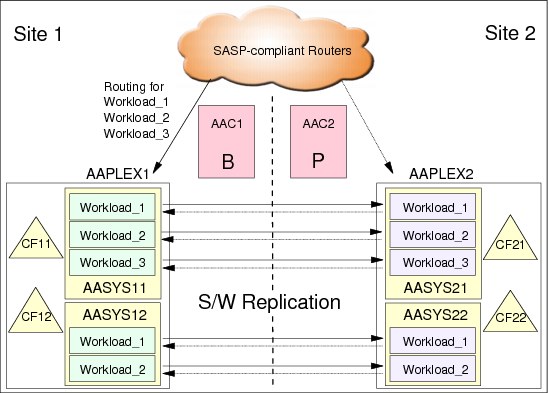
Figure 7-17 GDPS/Active-Active environment sample for Site1 shutdown script
The sequence of events required to completely shutdown Site1 is as follows:
1. Stop routing transactions for all workloads to AAPLEX1.
2. Wait until all updates on AAPLEX1 are replicated to AAPLEX2. In this example we are assuming these are non-DB2 workloads and therefore full automation for controlling whether data has drained or not is not yet available.
3. Stop replication from AAPLEX1 to AAPLEX2.
4. Activate On/Off Capacity on Demand (OOCoD) on the CECs running the AAPLEX2 systems and CFs (although not shown in the diagram, for this example we assume the CECs are named CPC21 and CPC22).
5. Start routing transactions for all workloads to AAPLEX2.
6. Stop the AASYS11 and AASYS12 systems.
7. Deactivate the system and CF LPARs in Site1.
The planned action script required to accomplish the Site1 shutdown for this environment is shown in Example 7-3.
Example 7-3 Sample Site1 shutdown script
COMM=‘Switch all workloads to Site2 and Stop Site1’
ROUTING=‘STOP WORKLOAD=ALL SITE=AAPLEX1’
ASSIST=‘WAIT UNTIL ALL UPDATES HAVE DRAINED - REPLY OK WHEN DONE’
REPLICATION=‘STOP WORKLOAD=ALL FROM=AAPLEX1 TO=AAPLEX2’
OOCOD=‘ACTIVATE CPC=CPC21 ORDER=order#’
OOCOD=‘ACTIVATE CPC=CPC22 ORDER=order#’
ROUTING=‘START WORKLOAD=ALL SITE=AAPLEX2’
SYSPLEX=‘STOP SYSTEM=(AASYS11,AASYS12)’
SYSPLEX=‘DEACTIVATE AASYS11’
SYSPLEX=‘DEACTIVATE AASYS12’
SYSPLEX=‘DEACTIVATE CF11’
SYSPLEX=‘DEACTIVATE CF12’
These sample scripts demonstrate the power of the GDPS scripting facility. Simple, self-documenting script statements drive compound and complex actions. A single script statement can operate against multiple workloads or multiple systems. A very complex procedure can be described in a script by coding just a handful of statements.
Another benefit of such a facility is the reduction in skill requirements to perform the necessary actions to accomplish the task at hand. For example, in the workload switch and the site shutdown scenarios, depending on your organizational structure within the IT department, you might have required database, application/automation, system, and network skills to be available to perform all of the required steps in a coordinated fashion.
Batch scripts
GDPS also provides a flexible batch interface to invoke planned action scripts. These scripts are not (and cannot be) invoked from the GDPS web interface, but are invoked from some other planned event external to GDPS. The initiating event can be, for example, a job, or messages triggered by a job scheduling application.
This capability, along with the Query Services described in 7.4.4, “GDPS/Active-Active Query Services” on page 204, provides a rich framework for user-customizable automation and systems management procedures.
Switch scripts
As described in 7.3.1, “GDPS/Active-Active - a deeper dive” on page 185, in the event of workload or entire site failure, GDPS performs the necessary steps to switch one or more workloads to the standby site. This switching, based on the selected policy, can be completely automatic with no operator intervention or can occur after operator confirmation. However, in either case, the steps required to switch any workload are performed by GDPS and no scripts are required for this.
Although GDPS performs the basic steps to accomplish switching of affected workloads, there might be additional actions specific to your environment that you want GDPS to perform along with the workload switch steps. One such example can be activating CBU for additional capacity in the standby site.
Switch scripts are Unplanned actions that run as a result of a workload failure or site failure detected by GDPS. These scripts cannot be activated manually. They are initiated automatically, if you have coded them, as a result of an automatic or prompted workload or site switch action initiated by GDPS. The intent of Switch scripts is to complement the standard workload/site switch processing that is performed by GDPS.
7.4.4 GDPS/Active-Active Query Services
GDPS maintains configuration information and status information in NetView variables for the various elements of the configuration that it manages. GDPS Query Services is a capability that allows client-written NetView REXX programs to query the value for numerous GDPS internal variables. The variables that can be queried pertain to the GDPS environment itself (such as the Version/Release level of the GDPS control code), the sites, the sysplexes, and the workloads managed by GDPS/Active-Active.
Query Services allows clients to complement GDPS automation with their own automation code. In addition to the Query Services function, which is part of the base GDPS product, GDPS provides a number of samples in the GDPS SAMPLIB library to demonstrate how Query Services can be used in client-written code.
7.5 GDPS/Active-Active co-operation with GDPS/PPRC
In an Active-Active environment, it is essential that each of the sysplexes running the Active-Active workloads is as highly available as possible. As such, we recommend that the Active-Active workloads are Parallel Sysplex enabled, data sharing applications. Although this eliminates a planned or unplanned system outage from being a single point of failure, disk data within each local sysplex is not protected by Parallel Sysplex alone.
In order to protect the data for each of the two sysplexes comprising the GDPS/Active-Active environment, these sysplexes can be running GDPS/PPRC with PPRC and HyperSwap which complement and enhance local high/continuous availability for the given sysplex(es). We describe the various capabilities available with GDPS/PPRC in Chapter 3, “GDPS/PPRC” on page 51.
With GDPS/Active-Active and GDPS/PPRC monitoring and managing the same production systems for a given sysplex, certain actions must be co-ordinated such that the GDPS Controlling systems for the two environments do not interfere with each other, or that one environment does not misinterpret actions taken by the other environment.
For example, it is possible that one of the systems in the sysplex needs to be re-IPLed for a software maintenance action. The re-IPL of the system can be performed either from a GDPS/Active-Active Controller or using GDPS/PPRC that is running on all systems in the same sysplex. Assume that you initiate the re-IPL from the GDPS/Active-Active Controller. GDPS/PPRC will detect that this system is no longer active. It will interpret what was a planned re-IPL of a system as a system failure and issue a takeover prompt.
The GDPS/Active-Active cooperation with GDPS/PPRC provides coordination and serialization of actions across the two environments to avoid issues that can stem from certain common resources being managed from multiple control points. In our example, when you initiate the re-IPL from the Active-Active Controller, it will communicate this to the GDPS/PPRC Controlling system. The GDPS/PPRC Controlling system will lock this system as a resource so that no actions can be carried out against it until the Active-Active Controller signals completion of the action. This same type of coordination takes place regardless of whether the action is initiated by GDPS/Active-Active or GDPS/PPRC.
GDPS/Active-Active can support coordination with GDPS/PPRC (or GDPS/HM) running in either or both of the Active-Active sites.
In Figure 7-18 on page 206, we show a GDPS/Active-Active environment across two regions, Region A and Region B. SYSPLEXA in Region A and SYSPLEXB in Region B comprise the two sysplexes managed by GDPS Active-Active. Systems AAC1 and AAC2 are the GDPS/Active-Active Controller systems. Additionally, each of these sysplexes is managed by an instance of GDPS/PPRC, with systems KP1A/KP2A being the GDPS/PPRC Controlling systems for SYSPLEXA, and KP1B/KP2B being the GDPS/PPRC Controlling systems in SYSPLEXB. The GDPS Active-Active Controllers have communication in place to each of the GDPS/PPRC Controlling systems in both regions. It is this communication that makes the cooperation support possible.
SYSPLEXA contains the data for the Active-Active workloads, as well as other data for applications running in the same sysplex but not managed by Active-Active, plus the various system infrastructure data which is also not managed by Active-Active. All of this data belonging to SYSPLEXA is replicated within Region A using PPRC and is HyperSwap protected, managed by GDPS/PPRC. Additionally, the Active-Active data is replicated via software replication to SYSPLEXB.
Similarly, there is another instance of GDPS/PPRC managing SYSPLEXB with the Active-Active data as well as any non Active-Active data belonging to SYSPLEXB being replicated via PPRC and HyperSwap protected within Region B.
Each of SYSPLEXA and SYSPLEXB could be running in a single physical site or across two physical sites within their respective regions.
All of the data within both sysplexes are GDPS/PPRC HyperSwap protected, meaning that disk within a region is not a single point of failure and the sysplex can continue to function in the event of planned or unplanned disk outages. HyperSwap is transparent to all applications running in the sysplex (assuming that the data for all applications is replicated with PPRC). This means that it is also transparent to all of the subsystems in charge of running the Active-Active workloads, replicating the Active-Active data, and monitoring the Active-Active environment. HyperSwap of disks within a region is transparent to the cross-region software replication process. Software replication will only know about and capture data from the logs on the current primary PPRC volumes. If there is a HyperSwap, software replication simply continues capturing data from the logs which are now on the new primary volumes.

Figure 7-18 GDPS/Active-Active co-operation with GDPS/PPRC
In addition to the HyperSwap protection, GDPS/PPRC provides a number of additional facilities and benefits which were discussed in detail in Chapter 3, “GDPS/PPRC” on page 51. Given the capabilities of GDPS/PPRC, we would expect that clients would perform most of the day-to-day system, sysplex and PPRC management activities for each of the two sysplexes using the respective GDPS/PPRC facilities. On the other hand, GDPS/Active-Active must be used for management and switching of the Active-Active workloads and replication. Finally, management (actions such as STOP, IPL and so on) of the Active-Active controllers can only be performed using GDPS/Active-Active since these systems are outside of the respective sysplexes and GDPS/PPRC scope of control is limited to the systems in the sysplex.
In summary, GDPS/Active-Active and GDPS/PPRC can be deployed in a complementary fashion and these products provide the necessary controls to facilitate any coordination that would be required when operating on common resources.
7.6 GDPS/Active-Active disk replication integration
The primary focus for GDPS/Active-Active is to provide near-continuous availability for your Active-Active workloads. The GDPS/Active-Active disk replication integration functions are designed to complement the GDPS/Active-Active functions and provide disaster recovery provision for your entire production sysplexes under the control of GDPS/Active-Active. This is done by integrating disk-based replication control into GDPS/Active-Active so that you have the ability to manage and control aspects of your disaster recovery provision for these sysplexes from a single point. At this time, this support is provided in conjunction with the GDPS/MGM solution that would be implemented for protection of the entire production sysplexes which are running both Active-Active and non-Active-Active workloads.
Figure 7-19 shows a GDPS/Active-Active environment where you have two Active-Active workloads that are both active in Sysplex A within Region A. In addition, other workloads such as batch or processing other non-Active-Active work are running in Sysplex A. In Sysplex B (in Region B), there are the standby instances of the Active-Active workloads plus other non-Active-Active work. The data for the Active-Active workloads is software-replicated between Sysplex A and Sysplex B. Both Sysplex A and Sysplex B have local disk resilience for the entire data (data used by Active-Active applications, the system infrastructure data and data used by other, non-Active-Active applications) provided by PPRC and HyperSwap managed by GDPS/PPRC plus an out of region DR copy for the entire data provided by Global Mirror (managed by GDPS/GM). Both the PPRC and GM copies, although not shown in this diagram, are being managed using GDPS/MGM.
Figure 7-19 Integration of hardware and software replication
A number of scenarios are supported through disk replication integration such as:
•Initial startup of replication
•Prepare the DR copy (for example the GDPS/GM practice FlashCopy) for a DR test
•Initiate a planned switch to the DR copy for a sysplex
•Initiate disaster recovery for a sysplex
•Return to normal configuration following a DR invocation or planned switch
Using the GDPS/Active-Active Controller to perform GDPS/Active-Active related operations as well as the hardware replication actions greatly simplifies operations since all of these actions are performed from a single point of control. Without this integration, it would be necessary to execute different steps of a complex operation (such as a planned region switch of an entire sysplex) by executing different steps on multiple different controlling systems.
The disk integration function provides simple, high-level primitives whereby a single script statement coordinates performing of multiple disk replication-related operations across the GDPS/PPRC and GDPS/GM environments that comprise the GDPS/MGM configuration. For example, assume that you want to perform a planned region switch of Sysplex A to its DR hardware replica in Region B: first, you would switch the Active-Active workloads to run in Sysplex B, then you need to stop all of the systems in Sysplex A (both of these actions can be performed using native GDPS/Active-Active functions). Next, in order to bring up Sysplex A on the hardware replica in Region B, there are multiple disk replication-related steps. We won’t get into the details of these steps here, but some of these need to be performed by the GDPS/PPRC Controlling system, and others need to be performed by the GDPS/GM Controlling system.
With the GDPS/Active-Active disk integration capability, all of these disk replication steps are boiled down to a single script statement (for this example, DISKREPLICATION SWITCH SYSPLEX=SYSPLEXA PLANNED), which is initiated from and coordinated by the GDPS/Active-Active Controller.
In summary, GDPS/Active-Active in conjunction with GDPS/MGM provide a comprehensive set of capabilities to automate out-of-region, near-continuous availability (for Active-Active workloads) and disaster recovery (for all workloads) for your production sysplexes using GDPS/Active-Active as the single point of control.
7.7 Flexible testing with GDPS/Active-Active
The best testing possible to understand if a workload is able to run in the recovery location is to actually run it there. As the saying goes, “The test of the pudding is in the tasting.” GDPS/Active-Active is very well positioned for this task because the application is already running in both locations and providing some level of confidence that the infrastructure in either site is able to sustain the workload. For complete confidence, you will additionally need to switch the workload such that the previously standby instance becomes active and actually processes transactions for some period of time.
It is easy to toggle a workload between sites in a GDPS/Active-Active setup. The workload can be periodically switched to run in one site or other site (in a planned manner) in a matter of seconds, with no data loss. Running the workload live in the other site with transactions being routed to it will give you the best opportunity to assess whether there are adjustments needed to your infrastructure and/or operating procedures and ensure that both of your sites are ready to assume live workloads.
Creating workload failures to test unplanned workload switching is also quite simple. However, we know that not all clients are willing to carry out such tests live in their production environments, no matter how small the expected service disruption might be.
It is best practice to maintain a sandbox testing environment that is somewhat representative of the production environment. If you already have a sandbox testing environment for Parallel Sysplex, this can be extended such that you have a test GDPS/Active-Active environment by adding another sandbox sysplex in the other site and a couple of Controllers for the sandbox GDPS.
If you do not have a sandbox sysplex but have, for example, a development sysplex, this can be extended to serve as a testing environment. Such a test environment will let you test new levels of software components or maintenance to these components before you introduce such changes into production. The test GDPS/Active-Active will also let you test both planned and at least some portion of unplanned outage and switch scenarios before they are tested in production. And as previously mentioned, various scenarios might never get tested in production, in which case the testing in the test environment can still provide an indication regarding whether the solution is set up properly and can be expected to work.
7.8 GDPS/Active-Active services
As explained, GDPS/Active-Active touches on much more than simply data replication. It also touches many other aspects in your environment such as sysplex, automation, network, workload routing, workload management, testing processes, planned and unplanned outage scenario testing and so on.
Most installations do not have all these skills readily available, and it is extremely rare to find a team with this range of skills across many implementations. However, the GDPS/Active-Active offering includes just that: access to a global team of specialists in all the disciplines you need to ensure a successful GDPS implementation.
Having said that, the most successful GDPS projects are those in which IBM and client skills form a unified team to perform the implementation.
Specifically, the Services component of GDPS/Active-Active includes some or all of the following tasks:
•Planning to determine availability requirements, configuration recommendations, implementation, and testing plans
•Installation and necessary customization of:
– NetView
– System Automation
• Customization for coexistence with other automation product
– Multisite Workload Lifeline Advisor
– Tivoli Monitoring
•Data replication implementation:
– Bandwidth analysis
– Installation and necessary customization of
• InfoSphere Data Replication Server for z/OS (DB2, IMS, or VSAM)
•Setup of SASP compliant routers/switches
•Assistance with cross-site connectivity for WAN and SE/HMC LAN
•GDPS/Active-Active automation code installation and customization
– Training on GDPS/Active-Active setup and operations
– Assistance with planning, coding and testing GDPS scripts and scenarios
– Assistance with planning and implementing GDPS/Active-Active cooperation and/or integration with GDPS/PPRC and/or GDPS/MGM
•Project management and support throughout the engagement
The services that IBM can provide in conjunction with a high availability and disaster recovery project are not restricted to those that we have listed. Here we have provided a list of services that specifically relate to GDPS/Active-Active implementation. The sizing of the services component of each project is tailored for that project based on many factors, including what automation and/or replication is already in place, which of the prerequisite products are already installed, and so on. This means that the services and skills provided as part of those services are tailored to the specific needs of each particular client and implementation.
7.9 GDPS/Active-Active prerequisites
Refer to the GDPS web site to find the most current list of prerequisites for GDPS/Active-Active:
7.10 GDPS/Active-Active comparison to other GDPS offerings
In each of the chapters that describe the other GDPS products that are based on hardware replication, we provide a table to compare the characteristics of these solutions against each other at a high level. We do not include GDPS/Active-Active in these comparisons because it is a somewhat “apples to oranges” comparison.
You have seen that GDPS/Active-Active is fundamentally different than the other GDPS products. It is based on software replication rather than hardware, and it is workload-level management and switch rather than system-level management and restart.
Furthermore, we have discussed how GDPS/Active-Active is not necessarily mutually exclusive with other GDPS products and how GDPS/PPRC or GDPS/MGM can be combined with GDPS/Active-Active to provide a comprehensive, robust near-continuous availability and disaster recovery solution for your enterprise.
Basic positioning and comparison for GDPS/Active-Active against the other GDPS products is discussed in 7.1.1, “Positioning GDPS/Active-Active” on page 174.
7.11 GDPS/Active-Active summary
GDPS/Active-Active is a powerful offering that facilitates near-instantaneous switching of workloads between two sites that can be separated by virtually unlimited distances. Based on asynchronous software replication, planned switches can be accomplished with no data loss (RPO 0). When sufficient replication bandwidth is provided, the RPO can be as low as a few seconds in the event of an unplanned workload switch.
GDPS/Active-Active provides a range of capabilities, through an intuitive web interface and/or using simple yet very powerful scripting, for workload management, workload routing, data replication management, management of system and hardware resources for planned and unplanned events. Through extensive monitoring and failure detection mechanisms, unplanned workload switches can be completely automated, removing human intervention and optimizing RPO.
For enterprises that require very high levels of protection with near zero RPO and RTO at distances beyond the practical reach of a GDPS/PPRC active/active configuration, GDPS/Active-Active is uniquely positioned to meet these requirements for critical workloads.
1 The distance between sites in a GDPS/PPRC Active/Active configuration that any client can tolerate will depend on the client’s application workloads and service level requirements. Each client must test with its own applications and workloads to determine the distance it can achieve. Nearly all clients running GDPS/PPRC Active/Active workloads are running their two sites at a 20 km distance or less. However, this does not necessarily mean that somewhat larger distances are not possible.
2 Note that at this time the ability to switch workloads with a single command is only possible for workloads that use DB2 data exclusively. The next and final site shutdown example shows how non-DB2 workloads would be switched in the context of a site shutdown scenario.
..................Content has been hidden....................
You can't read the all page of ebook, please click here login for view all page.