
The objective of analysis is to produce the first approximation of the shape of the solution and to lay the groundwork for design. Similarly, the objective of design is to lay the groundwork for implementation. Analysis, design and implementation are parts of a continuum of system refinements from requirements to working code.
In this chapter, we describe the activities that produce this “first approximation” of a solution that realizes the requirements defined in Chapter 6, Requirements. This solution will then be refined in Chapter 8, Design and ultimately implemented in Chapter 9, Implementation.
Analysis is sometimes overdone, resulting in “analysis paralysis” and a result that is overengineered. The goal of the analysis activities described in this chapter is to get you to a design and an architecture as quickly as possible, producing “just enough” to demonstrate that you understand the current set of requirements and that those requirements have been appropriately allocated to parts of the solution.
The primary analysis artifacts we describe in this chapter are the Design Model and the User-Experience Model.
The Design Model contains the key elements of the software solution and their organization, as well as the Use-Case Realizations that describe how the Use Cases are realized in terms of these elements. During analysis, we concentrate on Analysis Classes and Use-Case Realizations expressed in terms of those Analysis Classes. Consistent with our view of analysis and design as a continuum, we do not maintain a separate Analysis Model.
The User-Experience Model provides an abstraction of the user interface elements and the user's interaction with the system. It contains Screens, Use-Case Storyboards, and a Navigation Map. The Use-Case Storyboards show how the Use Cases are realized in terms of Screens, and the Navigation Map shows the legal navigation paths between those Screens. We use the User-Experience Model as a contract between the presentation and business aspects of the system. A separate User-Experience Model is not needed if the system does not have a user-experience aspect (for example, no user interface), or if that aspect is very well known, or of minor importance. In such cases, the relevant aspects of the user-experience can be captured in the Design Model (specifically, in the boundary Analysis Classes).
An “outline” of the proposed architecture is also defined and documented in the Software Architecture Document. However, this architecture is not truly defined until design (see Chapter 8).
As discussed in Chapter 3, An Introduction to the Rational Unified Process, the analysis and design activities vary throughout the development life cycle as shown in Figure 7.1.

The analysis activities are most visible during the Elaboration phase where we are focused on establishing the software architecture. During this phase, we concentrate on analyzing those requirements that are considered architecturally significant. During the Construction phase, we analyze any remaining requirements, but this analysis is not as extensive as that performed during the Elaboration phase because most of the major system elements have already been discovered. The time we spend on analysis continues to taper off throughout the Construction phase, as the number of requirements that we have not analyzed decreases and the focus shifts to implementation. We may need to perform some minimal analysis activities even into the Transition phase, as changes to the requirements are introduced based on feedback received when transitioning the system to the user, though this is unlikely.
The analysis portion of the Analysis and Design discipline in the J2EE Developer Roadmap is described using two workflow details, as shown in Figure 7.2. These are (1) Define an Initial Architecture and (2) Analyze Behavior.

Analysis concentrates on two aspects of the system (1) its overall architecture and (2) a first approximation of the system elements and how they interact to realize the system functional behavior. Each of these aspects is reflected in the roadmap.
The activities of the Define an Initial Architecture workflow detail focus on sketching out the software architecture, which is further refined in design (see Chapter 8).
The activities of the Analyze Behavior workflow detail focus on:
Identifying the elements of the user interface (Screens) and detailing the user interactions with the system (Use-Case Storyboards).
Identifying the Analysis Classes, their responsibilities and their inter actions, where the Analysis Classes represent the first approximation of the system elements that are then used during design to identify the design elements.
The purpose of the Define an Initial Architecture workflow detail is to create an initial “sketch” of the system architecture that leverages any existing Reference Architectures[1] or architectural frameworks. This “sketch” includes the overall structure of the system, its key abstractions, and its mechanisms. The identified key abstractions are then used to jump-start the analysis activities in the Analyze Behavior workflow detail.
The Define an Initial Architecture workflow detail is where we start to think about how to best leverage the technologies provided by the J2EE platform to meet both the functional and nonfunctional requirements of the system.
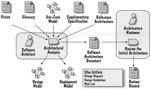
Figure 7.3 provides an overview of this workflow detail. As we show in the diagram, the Architectural Analysis activity results in an initial architecture that is reflected in initial versions of the Design Model and Deployment Model, and is documented in the Software Architecture Document (see Appendix A, Describing a Software Architecture). The initial architecture is then reviewed in the Review the Initial Architecture activity before the analysis of the Use Cases starts in the Analyze Behavior workflow detail, which is described in a later section.
In this activity, we make sure that the initial architecture takes into account the technologies and mechanisms that are provided by the J2EE platform.
In this step, we create an overview of the architecture based on experiences developing similar systems, or systems in similar domains, or possibly by reusing an existing Reference Architecture. This is typically a simple step to perform when developing with J2EE technologies, since there are a number of standard deployment configurations on which we can base our initial architecture (see Chapter 2, An Introduction to the Java 2 Platform, Enterprise Edition). Each of these deployment configurations exhibits different characteristics, so here we select one based upon a number of factors. Some factors that should be considered when selecting a deployment configuration include: maintainability (how do you isolate changes in one tier so they don't affect other tiers, how easy is it to deploy upgrades?), performance and scalability (how easy is it to add additional computing resources?), and reliability (what happens if one of the resources goes down?). For more information on how the different J2EE deployment configurations address these concerns, see Chapter 2).
An architecture overview can take many forms. It can be a single “rich” picture or several UML diagrams. The overview is documented in the Software Architecture Document. In Figure 7.4, we show the architecture overview for the Online Auction application.
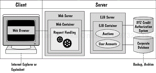
This diagram depicts the initial architectural decisions made for the Online Auction application. Specifically, we selected a multitier J2EE deployment configuration, with separate Web and EJB servers. Elements in the Web container will handle the user's requests, while elements in the EJB container will handle the business logic (auction and user account management). We also show the connection of the system to the external “XYZ Credit Authorization System” (remember the “Credit Service Bureau” Actor from requirements?), as well as the existence of a “Corporate Database” that supports the back up and archival of business data.
The architecture overview is typically created in an early iteration of the project to explore different architectural options and to identify the constraints imposed by each option. For example, if we choose a multitier deployment configuration, then we know that the client does not connect directly to the database. The architecture overview then allows us to convey an early understanding of the architecture of the system to the customer, the development team, and other stakeholders.
An important part of Architectural Analysis is to identify assets that could be used as the building blocks of the system. For example, in the Online Auction application, we may choose to use a third-party credit authorization capability rather than writing this ourselves. The decision to use an existing asset is based upon a number of factors, including the fit of the asset with our needs, and the costs involved. There are several types of assets that can be considered, such as (but not limited to) industry models, frameworks, components and class libraries. If a Reference Architecture is being used as the basis for the software architecture, then any assets associated with the Reference Architecture are considered as well.
Using the architecture overview and the identified assets, we develop a high-level Deployment Model that shows the physical nodes of the system and the connections between the nodes. This allows us to gain an understanding of the physical distribution and operational complexity of the system.
In Figure 7.5, we show an example of the initial Deployment Model for the Online Auction application. This diagram reflects the architecture overview shown in Figure 7.4. In particular, the Web container(s) will run on separate nodes than the EJB container(s), and we model separate nodes for the external Credit Authorization System and the Corporate Database.
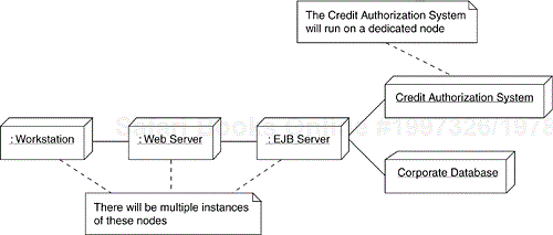
The initial Deployment Model is documented in the Software Architecture Document.
The Design Model is a key artifact that is used to communicate the logical structure of the system, which organizes the analysis and design model elements. In this step we decide on the structure of the Design Model (that is, we de fine the Design Packages that are used to partition the Design Model elements).
Rather than discussing a number of equally valid structures of the Design Model, we discuss a specific structure[2] that we adopted for the Online Auction application. This structure is shown in Figure 7.6.
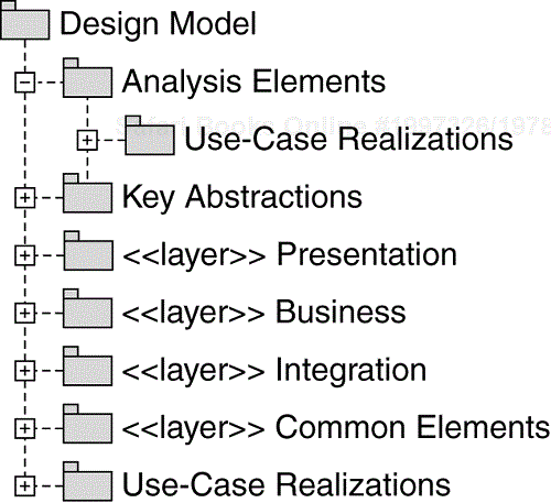
The “Analysis Elements” package represents the “analysis sandbox.” This package is where the analysis elements (Analysis Classes and analysis-level Use-Case Realizations) reside. An analysis-level Use-Case Realization de scribes how a Use Case is performed by a collaboration of Analysis Classes. All analysis-level Use-Case Realizations exist in the “Use-Case Realizations” sub-package of the “Analysis Elements” package. Analysis Classes and analysis-level Use-Case Realizations are used as a basis for design, but are not maintained (as discussed in Chapter 4, Introduction to the J2EE Developer Roadmap, we do not maintain a separate Analysis Model). For more information on how these analysis elements are used in design, see Chapter 8, specifically, the Identify Design Elements activity and the Use-Case Design activity.
The “Key Abstractions” package is where we maintain an analysis-level view of the key abstractions (key business concepts) of the system. For more information on key abstractions and why they are important, see the next step, Identify Key Abstractions.
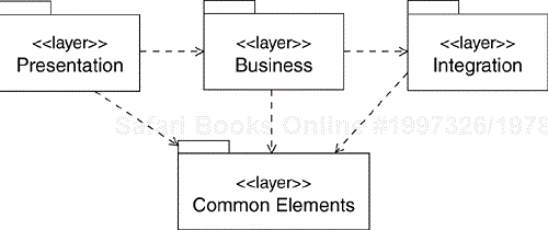
The «layer» packages represent the separate areas of concern within the system, specifically handling interactions with the end user (Presentation layer), performing business functionality (Business layer), and providing access to backend resources, including databases and external systems (Integration layer). There is also a Common Elements layer that contains the design elements that are common across layers. The relationship among these packages is shown in Figure 7.7.
The “Use-Case Realizations” package contains a design-level Use-Case Realization for each Use Case. A design-level Use-Case Realization describes how a Use Case is performed by a collaboration of design elements.
The purpose of this step is to identify the key abstractions of the system and their attributes, as well as any semantic relationships[3] between the key abstractions. Key abstractions are system-wide concepts derived primarily from the requirements artifacts (such as the Vision, Glossary, Supplementary Specification and Use-Case Model), as well as knowledge of the system's business domain. Key abstractions are represented in the UML as classes with the stereotype «entity».
For the Online Auction application, we identified the key abstractions by looking at the Glossary and reading through the use-case descriptions and identifying those terms repeatedly used to describe the functionality of the system. We spent some time understanding what each of the key abstractions meant in the context of our system and its domain. We then identified attributes and relationships between the key abstractions, which helped us to express their overall semantics. The results are shown in Figure 7.8.
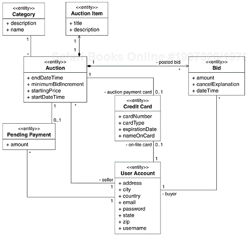
Figure 7.8 captures important semantics of the key abstractions in our application. An Auction consists of a single Auction Item for which there can be any number of Bids posted. Every Auction belongs to a specific Category and there can be any number of Auctions within the same Category. A user (represented by a User Account) can place any number of Bids as a Buyer, or can participate in an Auction as the Seller. A user can optionally have a Credit Card on file that can be used to pay the transaction fee for a closed Auction. If the fee for an Auction cannot be collected using that Credit Card, a Pending Payment is recorded against the User Account for the Auction.
We will use these key abstractions as a starting point when we identify Analysis Classes during the Use-Case Analysis activity. Using this approach, we significantly reduce the possibility that these key concepts will be defined in conflicting ways when we analyze the individual Use Cases.
The key abstractions are placed in the “Key Abstractions” package of the Design Model, and are documented in the Logical View of the Software Architecture Document.
An analysis mechanism is an architectural capability that represents a common solution to a common problem. Mechanisms represent general capabilities of the system that provide functionality that interacts with, or supports, the basic system functionality. Examples of common architectural needs that may be addressed with a mechanism include persistency, inter-process communication, transaction management and security.
In this step, we look at the key services we might need going forward and describe what we think they should do. The Supplementary Specification provides excellent “inspiration” for analysis mechanisms, as mechanisms are often used to address system-wide requirements. J2EE provides support for many of these mechanisms “right out of the box,” and can help us think about what we should be considering for analysis mechanisms. At this point, all we do is identify the mechanism, provide a name and description. We will describe how these mechanisms are designed and implemented in Chapter 8 (specifically in the Identify Design Mechanisms activity).
The analysis mechanisms identified for the Online Auction application are listed in Table 7.1.
We document the mechanism's name and description in the Software Architecture Document.
Table 7.1. Analysis Mechanisms
| Name | Description |
|---|---|
| Authentication | Verifies that the user has the credentials to access the system |
| Authorization | Makes sure that a user requesting specific system services is author- ized to access and use those services |
| Messaging | Sends e-mail messages to the system users |
| Persistency | Stores system state |
| Presentation Request Processing | Handles user requests to the system made over the Web interface |
| System Parameter Management | Handles external parameters |
In this step, we review the initial architecture. This review serves as a “quality gate” that ensures that the proposed architecture supports the system requirements and provides an adequate starting point for analysis and design.
We document any discovered problems in Change Requests. Once the review is complete, we briefly capture the results of the review, including any action items, in a Review Record. A Review Record is a form filled out for each review that provides an auditable record of the review and its conclusions.
The following checkpoints describe things that should be kept in mind when reviewing the initial architecture.
The proposed architecture should be realistic, given the requirements captured in the Use-Case Model and the Supplementary Specification, and the projects risks documented in the Risk List. Someone generally knowledgeable in the problem domain should be able to easily understand it.
The initial structure of each of the models should be defined and should be consistent. The model structures should be consistent with the proposed architecture overview.
Mechanisms should be identified and described in the Software Architecture Document.
The key abstractions should be identified, along with any attributes, operations, and relationships. They should be consistent with the requirements, especially the Glossary entries.
The activities in the previous workflow detail, Define an Initial Architecture, focused on identifying the overall structure of the system, its key abstractions, and its mechanisms. The Analyze Behavior workflow detail concentrates on adding analysis-level system elements that realize the Use Cases to this initial structure. The identified key abstractions are used as a starting point for identifying these analysis elements. Figure 7.9 provides an overview of the activities performed and the artifacts produced in this workflow detail.
In the Analyze Behavior workflow detail, there are two “streams” of activities. In the first stream, the Model the User Experience activity considers how each Use Case is realized in terms of Screens. The result of this activity is the User-Experience Model that has been refined for the current iteration's Use Cases, which is then reviewed in the Review the User Experience activity.
The Use-Case Analysis activity represents the second stream where we consider how each Use Case is realized in terms of Analysis Classes. The result of this activity is the Design Model that has been refined for the current iteration's Use Cases, which is then reviewed in the Review the Analysis activity.
The activities performed in each stream take Use Cases as their primary input and produce appropriate “realizations” of these Use Cases in terms of their respective model elements (Screens and Analysis Classes). We should remember that the nature of these activities is to provide us with an analysis-level perspective of the system, and we should avoid the temptation to design the system at this stage, since this entails additional concerns as discussed in Chapter 8.
In this activity, we populate the User-Experience Model with elements that support the realizations of the Use Cases of the current iteration. Before we describe the process for identifying and modeling these elements, we briefly describe the structure of the User-Experience Model.
In Figure 7.10, we show the structure[6] of the User-Experience Model for the Online Auction application.
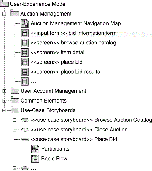
The “Use-Case Storyboards” package contains a Use-Case Storyboard for each Use Case in the Use-Case Model. Use-Case Storyboards describe the Screens the user navigates through while performing the Use Case. You can think of a Use-Case Storyboard as a Use-Case Realization that focuses exclusively on the user-interface elements of the Use Case.
We represent a Use-Case Storyboard as a UML collaboration instance with the stereotype «use-case storyboard». We give the Use-Case Storyboard the same name as the Use Case it realizes. If explicit traceability is desired from the Use-Case Storyboard to its associated Use Case, a realization relationship can be modeled as is shown in Figure 7.11. However, in most cases, using the same name for both the Use Case and the Use-Case Storyboard is probably enough. For more information on traceability, see Chapter 10, Additional Topics.

Each Use-Case Storyboard has a structural view and a dynamic view. The structural view describes the Screens that participate in the Use-Case Sto ryboard and the navigation paths between them. It is represented on a class diagram called “Participants.” The dynamic view describes the flow of Screens that occurs during the execution of the Use Case. It is represented as a set of interaction diagrams with at least one interaction diagram per use-case flow of events. The location of the diagrams representing these views is shown in Figure 7.10. The development of the structural and dynamic views of the Use-Case Storyboards is what we concentrate on in this activity.
In this step we identify the Screens the user will interact with during the execution of the Use Case.
Screens are the major modeling element of the User-Experience Model. We use Screens to represent that with which the user interacts. In a Web application, a Screen is a client-side element that represents everything the application generates for the user in a single client window. A Screen may contain multiple pages of information. For example, it could be a frameset that renders multiple HTML pages.
The following list describes the information we capture for each identified Screen.
Dynamic content. Dynamic content is the content displayed on the Screen that is provided by the business logic at runtime. Static content (for example, overall Screen structure, field names, titles, text, images, and client-side scripts) is not represented in the User-Experience Model since static content is often concerned with “look and feel” and does not affect the contract between the presentation and business aspects of the system (it is constant for each user of the system).
User-supplied content. The content provided by the user via input forms.
User actions. Actions that a user can perform on the Screen. For example, clicking on a button or selecting a menu item.
Before describing how to identify the participating Screens and the above information, we describe the basics of how to represent the User-Experience Model elements in the UML.
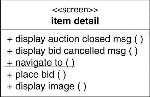
A Screen is modeled as a UML class with the stereotype «screen». The dynamic content of a Screen is modeled as a set of attributes of the Screen class as shown in Figure 7.12. The “item detail” screen is used to display information about an item that is available for auction such as the item title, item description, and the current highest bid that has been placed on the item.

The user-supplied content of a Screen is modeled using a separate User-Experience Model element called an “input form,” which is also modeled as a UML class, but has the stereotype «input form», as shown in Figure 7.13. The attributes of the input form are used to represent the user-supplied content. These input form attributes can be specified with an optional data type indicating the type of input element (such as Text, TextArea, Radio, Checkbox, and Select). We use separate «screen» and «input form» classes because their attributes represent different things. Screen attributes represent dynamic business content provided by the application, whereas input form attributes represent content provided by the user.
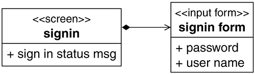
Input forms are always part of a Screen. Input forms never exist outside the context of a Screen and can never be navigated to directly (all navigation is to a Screen). The relationships between Screens and their input forms are modeled as composition relationships from the «screen» class to the contained «input form» class(es). In the example shown in Figure 7.13, the “signin” Screen is dis played when the user requests to sign into the system. It contains an input form (“signin form”) where the user enters their user name and password.
User actions are modeled as operations on the Screen or input form classes. An example of a Screen with user actions is shown in Figure 7.14. In this example, the user can place a bid on the item (“place bid” operation), as well as display the image of the item (“display image” operation), both from the item detail Screen. The “display” and “navigate to” operations represent screen creation/rendering actions that are invoked by the environment (the Web browser), not the user. Screen creation/rendering actions are modeled as static operations on the «screen» or «input form» class (hence the underlined name).
The key input to the process of identifying Screens participating in a Use Case is the use-case specifications developed during requirements, especially the detailed flows of events (see Chapter 6).
The following list describes ideas that we find helpful when identifying Screens:
Identify one central Screen to represent the main Screen with which a particular Actor interacts. The main Screen should be the window that is opened when the user launches the application, and is the place where the user spends a considerable part of his or her “use time.” If such a Screen already exists, reuse it. For example: an application's home Screen.
Look for functions the user will be performing in the system. Identify one Screen for each major system function (possibly one Screen per Use Case). For example, a “browse auction catalog” Screen, or a “place bid” Screen.
Look in the use-case specification for information interesting to the user, information that is manipulated by the system, and information that needs to be visible and managed in the user interface. Some of this information may end up being modeled as dynamic content on the same Screen or on separate Screens. For example, the de scription of the item available for auction is modeled as dynamic content on the “item detail” Screen instead of a separate Screen (see Figure 7.12).
When identifying Screens, try to reuse existing Screens wherever possible to eliminate redundancy, enhance consistency, and reduce the consolidation and reconciliation effort that occurs later amongst the individual Use-Case Storyboards.
To identify user-supplied content (and thus the need for input forms), look for places in the Use Case where the user must supply information to the system.
To identify user actions, examine the Use Case for requests the user makes of the system.
The initial set of Screens we identified for the “Place Bid” Use-Case Storyboard is shown in Figure 7.15. This diagram represents the initial content of the “Participants” diagram shown in Figure 7.10. Additional information (for example, navigation relationships) will be added to this diagram as we perform the remaining steps in this activity (see the Define the Screen Navigation Paths step).

The location of these Screens and the “Participants” diagram in the User-Experience Model is shown in 7.10.
In this step we take a look at the dynamic aspect of the Use-Case Story board—the Screen flows for the Use Case. The Screen flows describe how the use-case flows of events are realized in terms of the Screens identified in the previous step.
For each use-case flow of events, we create a UML interaction diagram (either a sequence diagram or a collaboration diagram) that describes the Screens that are navigated through during the execution of the Use Case. In the Screen flow diagrams, the objects are the Screen instances and the messages are associated with user actions that cause a navigation to occur from one Screen to another. A script can be added to the interaction diagram to describe the Screen flow, if a more detailed description is needed.
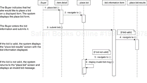
A sequence diagram describing the Screen flow of the “Place Bid” Use Case (basic flow) is shown in Figure 7.16. This diagram represents the content of the “Basic Flow” diagram shown in Figure 7.10. The objects shown on the diagram represent instances of the Screens and input forms identified in the previous step and shown on Figure 7.15. A very important aspect of this dynamic view of the Use-Case Storyboard is that it describes the transitions between the Screens caused by user-system interactions. In our case, all Screen transitions are initiated by some user action.
At this point, we have identified the Screens participating in the Use Case (Figure 7.15), and have modeled the flow between these Screens (Figure 7.16). Now we define the navigation paths that must exist between the participating Screens to support the Screen flows. Navigation paths are the relationships between Screens that define the valid transitions between Screens.
A transition between Screens is modeled as a UML directed association from the source «screen» or «input form» class to the destination «screen» class (the Screen being navigated to)[7]. The name of the navigation association should reflect the reason for the navigation (for example, if a “place bid” user action causes the navigation, the navigation association should be named “place bid”). Not all navigation associations need names, only those that add to the understanding of the diagram.
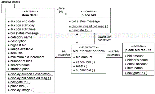
To identify the navigation paths, we examine the Screen flow diagrams. For every message, we define a supporting navigation path between the associated «screen» classes. For example, in Figure 7.16, the “place bid” user action on the “item detail” Screen causes the “place bid” Screen to be displayed. Thus, a navigation association must exist from the “item detail” Screen to the “place bid” Screen.
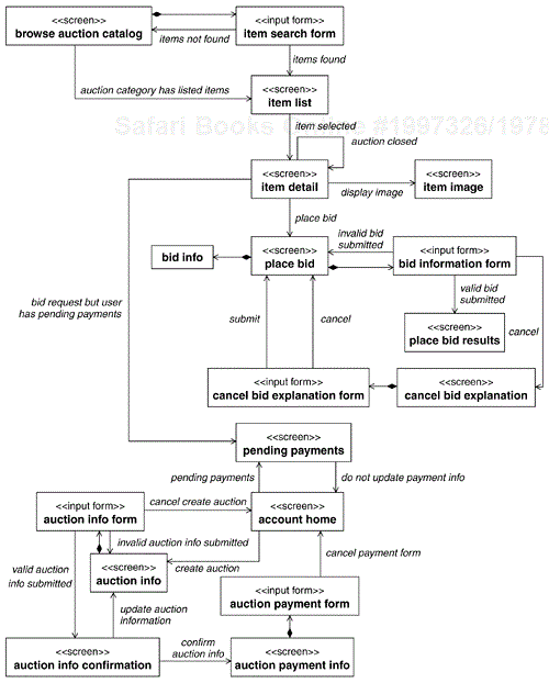
We add the Screen navigation paths to the Use-Case Storyboard “Participants” diagram created in the Identify the Participating Screens step (Figure 7.15). The resulting “Participants” diagram for the “Place Bid” Use Case is shown in Figure 7.17.
Once the user experience for each of the Use Cases in the current iteration has been individually analyzed, we perform the following steps looking at the resulting Use-Case Storyboards together.
At this point we have a Use-Case Storyboard for each Use Case being addressed in the current iteration. In this step we reconcile these individual Use-Case Storyboards and identify a set of Screens with consistent content, user actions, and navigation paths. This reconciliation is important since the analysis of separate Use Cases may have resulted in disparate content and user actions being allocated to the same Screen. Our goal is to produce a User-Experience Model that is consistent across all Use Cases.
The result of this reconciliation is the Navigation Map. The Navigation Map conveys the structure of the User-Experience Model by showing the system's Screens and the valid navigation paths between them. The Navigation Map is essentially the result of combining the participant diagrams of individual Use-Cases Storyboards[9]. For most systems, representing the entire Navigation Map (all of the Screens and their navigation paths) on a single diagram is not practical (the diagram would be too big). Thus, the Navigation Map is usually represented using multiple diagrams.
In the Online Auction application, we represent the Navigation Map using multiple diagrams, one diagram for each logical grouping of Screens. The Screens related to auction management and their navigation paths are shown in Figure 7.18. The User-Experience Model elements shown on this diagram span Use-Case Storyboards. The diagram contains participating Screens from the “Create Auction”, “Browse Auction Catalog”, and “Place Bid” Use-Case Storyboards. The location in the User-Experience Model of the “Auction Management Navigation Map” diagram (Figure 7.18) is shown in Figure 7.10.
Usability requirements are concerned with the system properties that make the system easy to use. System-wide usability requirements are documented in the Supplementary Specification, whereas usability requirements specific to a Use Case are documented in the Special Requirements section of the use-case specification. In any case, the purpose of this step is to make sure that all applicable usability requirements are addressed in the User-Experience Model. Where appropriate, traceability can be established between the applicable usability requirements and the user-experience elements. For more information on traceability, see Chapter 10.
In this step, we review the User-Experience Model. This review serves as a “quality gate” that ensures that the User-Experience Model follows the User-Experience Guidelines and is what the user is expecting. It is critical that the user “sign off” on the User-Experience Model before the design or implementation of the user interface is performed.
Problems discovered in the User-Experience Model or the User-Experience Guidelines are documented in Change Requests. Once the review is complete, the results of the review, including any action items, are captured in a Review Record.
The following checkpoints describe things that should be kept in mind when reviewing the user-experience artifacts.
There should be one Use-Case Storyboard for each Use Case being considered in the current iteration.
The Screen flows of the Use-Case Storyboards should be consistent with the associated use-case flows of events and with any constraintsidentified in the Supplementary Specification.
The Screens and Screen flows should be consistent with the guidelines provided in the User-Experience Guidelines.
For each Use-Case Storyboard, the participating Screens and the Screen flows should be consistent, which means that for every Screen instance on the Screen flow diagrams, the Screen class should appear on the “Participants” diagram, and every message on the Screen flow diagrams should correspond to a navigation path that appears on the “Participants” diagram.
The dynamic content and user actions defined for each Screen should support the Screen flows in which the Screen participates.
The usability requirements should be associated with the appropriate User-Experience Model elements.
The system's stakeholders, especially the end users, should accept the user experience. The user experience should be what the users expect.
In this activity, we populate the Design Model with Analysis Classes and analysis-level Use-Case Realizations that describe the realization of the Use Cases of the current iteration at the analysis level. Before we describe the process for identifying and modeling these elements, we briefly describe the structure of the Design Model.
In Figure 7.19, we show the structure of the analysis elements in the Design Model of the Online Auction application[11].
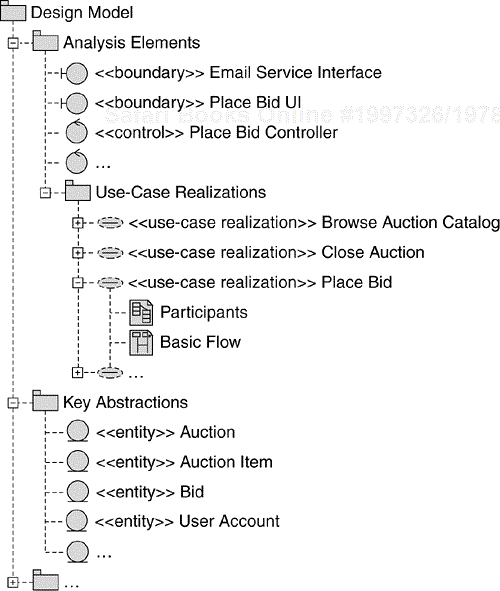
The “Use-Case Realizations” package contains an analysis-level Use-Case Realization for each Use Case in the Use-Case Model. Analysis-level Use-Case Realizations describe how the Use Case is realized in terms of Analysis Classes. Like Analysis Classes that will have design element counterparts, analysis-level Use-Case Realizations will have design-level counterparts that will exist in the Design Model (in the “Use-Case Realizations” package directly within the “Design Model” package shown in Figure 7.6). Thus, Use-Case Realizations provide the link between the requirements as documented in the Use Cases and the software solution that is initially described in terms of Analysis Classes, and then later in terms of design elements (see the Use-Case Design activity in Chapter 8).
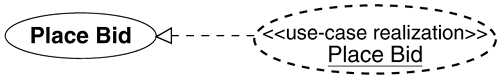
We represent a Use-Case Realization as a UML collaboration instance with the stereotype «use-case realization», and give it the same name as the Use Case it realizes. If explicit traceability is desired from the Use-Case Realization to its associated Use Case, a realization relationship can be modeled from the Use-Case Realization to its associated Use Case, as is shown in Figure 7.20. However, in most cases, using the same name for both the Use Case and the Use-Case Realization is probably enough. For more information on traceability, see Chapter 10.
Each analysis-level Use-Case Realization has a structural view and a dynamic view. The structural view describes the Analysis Classes that participate in the Use-Case Realization and the relationships between them. It is represented on a class diagram called “Participants”. The dynamic view describes the Analysis Class interactions that occur during the execution of the Use Case. It is represented as a set of interaction diagrams with at least one interaction diagram per use-case flow of events. The location of the diagrams representing these views is shown in Figure 7.19. The development of the structural and dynamic views of the analysis-level Use-Case Realizations is what we concentrate on in this activity.
In this step we identify the Analysis Classes that perform the behavior described in a Use Case, together with their attributes, responsibilities and relationships. The three types of Analysis Classes used to represent the system's internal behavior during analysis are summarized in Table 7.2.
Table 7.2. Analysis Class Types
| Analysis Class Type | UML Representation[12] | Description |
|---|---|---|
| Boundary | «boundary» | Boundary classes represent the boundary between the system and its environment. |
| Control | «control» | Control classes represent the control and coordination logic of the system. |
| Entity | «entity» | Entity classes encapsulate the information represented in the system. |
A boundary class is a class used to model the interactions between the system and its surroundings. In general, there is at least one boundary class for each Actor/Use Case pair. A system may have several types of boundary classes, representing interactions with a user, an external system, or a device (such as a printer). A boundary class that represents interactions with a user is a placeholder for the detailed user-experience modeling that is performed in the Model the User Experience activity. In other words, a single boundary class is a convenient abstraction for a set of Screens. The Screens and their navigation paths provide a more detailed representation of the user's interaction with the system than the single boundary class. Consistency between the Analysis Classes and the Screens is discussed later in the step Ensure Consistency with the User-Experience Model.
Control classes encapsulate use-case-specific behavior and handle the main control flows. You can start by identifying one control class per Use Case, and then refine this as more Use-Case Realizations are identified and additional commonality is discovered.
An entity class encapsulates information represented within the system, together with any attributes and associated behavior. Entity classes usually represent persistent system elements. As we saw in the Architectural Analysis activity, the key abstractions identified in the Identify Key Abstractions step were represented as entity classes, and these key abstractions are used as a starting point for identifying the entity classes participating in the Use Case being analyzed.
Figure 7.21 is a sequence diagram that shows typical interactions among the different types of Analysis Classes. Here we see an Actor interacting with a boundary class. The boundary class passes control to a control class that, in turn, coordinates the interactions between two entity classes.
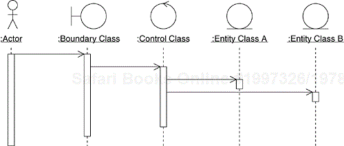
The decoupling of the boundary, control, and entity classes represents the separation of three aspects of the system: interactions with the environment (external interfaces), internal coordination and control flow (business logic) and state management (system information model). This makes the system more tolerant to change. For example, a boundary class decouples the system from its interactions with external elements (such as users, external systems and devices). A control class ensures that use-case-specific behavior is decoupled from entity classes, thus making the entity classes more reusable across Use Cases.
While developing the example Online Auction application, we applied a number of the heuristics described in the preceding paragraphs. Specifically, we defined one boundary class for each Actor/Use Case pair, one control class for each Use Case, and one entity class for system information referenced in the Use Cases. When identifying entity classes, we used the key abstractions identified in the Architectural Analysis activity (see Figure 7.8) as a starting point, as well as the common terms documented in the Glossary.
The Analysis Classes identified for the “Place Bid” Use Case are shown in Figure 7.22. This diagram represents the initial content of the “Participants” class diagram shown in Figure 7.19. Additional information (for example, relationships between Analysis Classes) will be added to this diagram as we perform the remaining steps in this activity (see the Describe the Analysis Classes step).
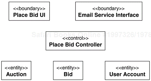
The location of these Analysis Classes and the “Participants” diagram in the Design Model is shown in Figure 7.19.
In this step we model the use-case flows of events in terms of the Analysis Classes that were identified in the previous step[13]. For each use-case flow of events, we create a UML interaction diagram (either a sequence diagram or a collaboration diagram) that shows how the Analysis Classes collaborate to perform the flow of events. In the interaction diagrams, the objects are instances of the Analysis Classes, and the messages represent the “responsibilities” of these Analysis Classes. A script (a textual annotation) can be added to the interaction diagram to describe the flow if a more detailed description is needed.
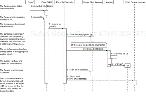
When developing the use-case flows for the Online Auction application, we followed the typical interactions between Analysis Classes shown in Figure 7.21. The sequence diagram for the “Place Bid” Use Case basic flow is shown in Figure 7.23. This “Basic Flow” diagram is placed within the Use-Case Realization, as shown in Figure 7.19.
At this point, we have identified the Analysis Classes participating in the Use Case, and have modeled the flows between them. It is now time to ensure that these classes have the appropriate attributes, responsibilities and relationships required to actually realize that Use Case. To do this, we examine the flow diagrams created in the previous step. These interaction diagrams help us determine the responsibilities and attributes of the various Analysis Classes, as well as help us identify the relationships between the Analysis Classes.
As mentioned earlier, the messages on the Use-Case Realization flow diagrams represent Analysis Class responsibilities. Thus, all of the responsibilities of an Analysis Class can be determined by looking at the incoming messages to instances of that Analysis Class on the flow diagrams. By convention, each Analysis Class responsibility is documented as a UML operation whose name is prefixed with “//”. As responsibilities are assigned to each Analysis Class, it is also worth considering the attributes that the Analysis Class must have in order to fulfill these responsibilities.
The Analysis Class relationships are also determined by looking at the Use-Case Realization flow diagrams. Each message between Analysis Class instances on the diagrams implies some kind of relationship between their respective Analysis Classes. Some of these relationships will represent a simple usage of another object (a UML dependency relationship). However, other relationships may imply a particular structural relationship between the respective classes (a UML association or aggregation relationship). Each of these interactions should be examined with the goal of identifying and documenting the nature of these relationships.
For example, in Figure 7.23, to process the user's request to create a bid, the Place Bid Controller must collaborate with the Buyer's User Account to see if the Buyer has any pending payments, and, if not, collaborate with the Auction to create the bid. Thus, the Place Bid Controller class must have a relationship with the User Account class and with the Auction class, as shown in Figure 7.24.

We add the Analysis Class relationships, responsibilities and attributes to the Use-Case Realization “Participants” diagram created earlier in the Identify the Participating Analysis Classes step (Figure 7.22). The resulting “Participants” diagram for the “Place Bid” Use Case is shown in Figure 7.24.
Once all of the Use Cases in the current iteration have been individually analyzed, we perform the following steps looking at the resulting Use-Case Realizations together.
At this point we have a Use-Case Realization for each Use Case being addressed in the current iteration. In this step we reconcile these individual Use-Case Realizations and identify a set of Analysis Classes with consistent responsibilities, attributes and relationships. This reconciliation is important since the analysis of separate Use Cases may have resulted in disparate respon sibilities being allocated to the same Analysis Class. Our goal is to produce a Design Model that is consistent across all Use Cases.
As discussed earlier, the Design Model and the User-Experience Model describe two different aspects of the system, and these two aspects must remain consistent. Before wrapping up the analysis activities for the current iteration, it is important that we “sync up” the Design Model and the User-Experience Model.
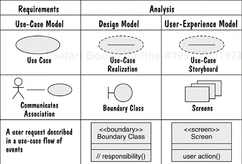
As discussed earlier, boundary classes are used to represent the interactions between the Actors and the system, and Screens are used to represent the user interface. The Screens and their navigation paths provide a user-centric view of the user's interactions with the system, compared with the system's view of those interactions, which is represented by a single boundary class. Thus, there is a relationship between boundary classes representing a user interface and Screens. The relationship between the Use-Case Model, Design Model, and User-Experience Model elements is summarized in Figure 7.25.
We make the following observations regarding these relationships.
A Use Case in the Use-Case Model is realized by a Use-Case Realization in the Design Model, and by a Use-Case Storyboard in the User-Experience Model.
The interactions between an Actor and a Use Case in the Use-Case Model map to a boundary class in the Design Model and a set of Screens in the User-Experience Model.
Every user request in the use-case description maps to a responsibility defined for a boundary class in the Design Model, which maps to a user action defined for a Screen in the User-Experience Model.
If desired, traceability can be explicitly modeled between the boundary Analysis Classes and the Screens using a UML dependency relationship with a «trace» stereotype that is drawn from the boundary class to the Screen. An example of such traceability is shown for the “Place Bid” Use Case in Figure 7.26. However, in many cases, such traceability does not have to be explicitly modeled, but can be derived based on the relationships between the Use-Case Storyboards and the Use-Case Realizations. For example, there is one Use-Case Storyboard and one Use-Case Realization for each Use Case. For a Use Case that has a user interface, there is at least one boundary class representing the user interface in the Use-Case Realization. These boundary class(es) map to the Screens participating in the associated Use-Case Storyboard. For more information on traceability, see Chapter 10.

In this step, a review of the analysis artifacts is performed. This review serves as a “quality gate” that ensures that the analysis artifacts are mature enough to support the subsequent design activities. Problems discovered in the artifacts are documented in Change Requests. Once the review is complete, the results of the review, including any action items, are captured in a Review Record.
The following checkpoints describe things that should be kept in mind when reviewing the analysis artifacts.
There should be one Use-Case Realization for each Use Case being considered in the current iteration.
The Use-Case Realization flow diagrams should be consistent with the associated use-case flows of events.
The allocation of responsibilities across Analysis Classes should be balanced and consistent (one Analysis Class should not be “doing it all”).
For each Use-Case Realization, the participating Analysis Classes and flows should be consistent. This means that for every Analysis Class instance on the flow diagrams, the Analysis Class should appear on the “Participants” diagram, and that every message on the flow diagrams should correspond to a relationship that appears on the “Participants” diagram.
The attributes and operations defined for each Analysis Class should support the flows in which the Analysis Class participates.
The boundary Analysis Classes in the Design Model and the Screens in the User-Experience Model should be consistent with each other.
The flows in the Use-Case Realizations should be consistent with the Screen flows in the Use-Case Storyboards.
The Analysis Classes should provide the dynamic content identified for the Screens.
The Use-Case Realizations should be consistent with the guidelines provided in the Design Guidelines.
At the completion of analysis, we have an analysis-level view of the system elements and their interactions in the Design Model, as well as a description of the users' interactions with the system in the User-Experience Model. In the next chapter, we describe how the results of analysis are used to develop a design that directly supports implementation.
Analysis is a critical part of the overall software development process and, if performed well, will result in a more robust and understandable design, with a clear separation of concerns and a balanced division of responsibility between system elements.
[1] A Reference Architecture is a predefined architectural pattern, or set of patterns, possibly partially or completely instantiated, designed and proven for use in particular business and technical contexts, together with supporting artifacts to enable their use. Often, these artifacts are harvested from previous projects.
[2] For a summary of the model structures we used for the Online Auction application, see Appendix B, Modeling Guidelines.
[3] The key abstraction relationships that exist at this point are those that are immediately obvious from the key abstraction definition.
[4] In this review, only the architecturally significant aspects of the models are reviewed, and that information is captured in the Software Architecture Document. Thus, the individual models are not listed as input artifacts to this activity.
[5] In practice, these steps are performed in parallel (for example, the Screens are identified and described at the same time the Screen flows are modeled). The ability to do this comes with experience. We have chosen to present the modeling of the user experience as a series of “passes” through the Use Case flows; however, the number of “passes” can be minimized as you become more experienced at applying the process.
[6] For a summary of the structures we used for the models of the Online Auction application, see Appendix B, Modeling Guidelines.
[7] Remember, input forms never exist outside the context of a Screen and thus, can never be navigated to directly.
[8] This “Participants” diagram contains user actions and navigation associations that are not modeled in the interaction diagram shown in Figure 7.16 (for example, canceling a bid, placing a bid on an auction that is closed). However, we have included them here for completeness.
[9] In fact, each Use-Case Storyboard “Participants” diagram can be considered a “mini” navigation map whose scope is the associated Use Case instead of the whole system.
[10] In practice, these steps are performed in parallel (for example, the Analysis Classes are identified and described at the same time the use-case flows are modeled). The ability to do this comes with experience. We have chosen to present Use-Case Analysis as a series of “passes” through the Use Case flows; however, you can minimize the number of “passes” as you become more experienced at applying the process.
[11] For a summary of the structures we used for the models of the Online Auction application, see Appendix B, Modeling Guidelines.
[13] We may even identify new Analysis Classes.