This chapter describes the design “half” of the Analysis and Design discipline. Analysis, the subject of the previous chapter, Chapter 7, Analysis, takes the system requirements and produces the initial sketch of the solution.
The objective of design is to take the results of analysis and produce a specification that can be efficiently implemented, which is the subject of the next chapter, Chapter 9, Implementation. The design is considered complete, when it is detailed enough to be implemented and tested.
The key inputs to design are the Design Model and the User-Experience Model. The Design Model captures the following results of analysis:
Key abstractions (modeled as entity Analysis Classes) and the relationships between them, which form the foundation of the description of what information must be stored and managed by the system[1]
Control classes that capture the flow of the system's Use Cases and identify the major “business” responsibilities that must be fulfilled by the system's design elements
Boundary classes that represent the interface between the system and elements that are external to the system
Use-Case Realizations that show how the Analysis Classes (boundary, control, and entity classes) interact in realizing the system's Use Cases.
The User-Experience Model captures the following results of analysis:
Screens and input forms that represent what information the user will see when working with the system, and
Use-Case Storyboards that show the navigation between Screens and represent the interactions between the user and the system, when the system Use Cases are performed.
The objective of design is to take these analysis artifacts and produce a set of design artifacts that can be directly implemented with the J2EE platform technologies. The primary output artifacts of design are Design Subsystems, Framework Components, Design Classes, and design-level Use-Case Realizations, all captured in the Design Model. Design also updates the Deployment Model, refines analysis mechanisms into design mechanisms, and converts an initial sketch of the architecture developed during analysis into its final design form.
As we explained in Chapter 3, An Introduction to the Rational Unified Process, the analysis and design activities vary through the development life cycle as shown in Figure 8.1.
Design activities can start in an iteration of the Inception phase when we may decide, for example, that we will base our solution on a set of existing software elements. These activities then pick up in the early iterations of the Elaboration phase, when we concentrate on designing the major (or as we often call them, architecturally significant) elements of the system. As we move into the iterations of the Construction phase, the design activities taper off and focus on what we could categorize as being peripheral or supporting elements.
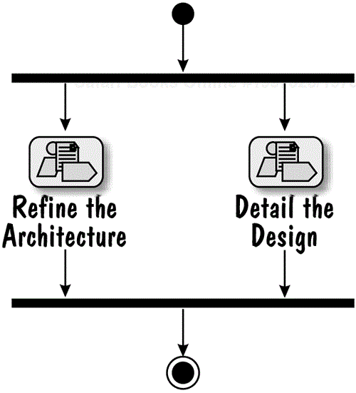
The J2EE Roadmap contains two concurrent workflow details, (1) Refine the Architecture and (2) Detail the Design, that represent the design aspects of the Analysis and Design discipline, and are shown in Figure 8.2.
The activities of the Refine the Architecture workflow detail focus on (1) fine-tuning the architecture that was initially articulated in the Define an Initial Architecture workflow detail of analysis and (2) providing a transition from the analysis to design by identifying the major design elements of the system.
The objective of the Detail the Design workflow detail is to keep on taking the identified design elements and refining them by working out the details of their content, behavior and relationships. As we have mentioned already, the refinement stops when there is enough detail for the design elements to be implemented.
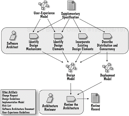
The Refine the Architecture workflow detail contains the activities shown in Figure 8.3.
The objectives of these activities are to:
Identify the design mechanisms of the system (in the Identify Design Mechanisms activity)
Identify major design elements of the system (in the Identify Design Elements activity)
Bring together the user-experience aspects (represented in the User-Experience Model) and the business aspects (represented in the Design Model) of analysis into a single design of the system (in the Identify Design Elements and Identify Design Mechanisms activities)
Identify the opportunity and the impact of incorporating (reusing) existing design (and related implementation) elements (in the Incorporate Existing Design Elements activity)
Consider the impact of concurrency and distribution on the system's architecture (in the Describe Distribution and Concurrency activity)
The resulting software architecture is reviewed for consistency in the Review the Architecture activity. The consistency and integrity of the architecture is maintained throughout the activities of the Detail the Design workflow detail discussed later in this chapter.
The outcome of the activities of this workflow detail is captured in the Design Model, the Software Architecture Document, the Design Guidelines and the Deployment Model.
As you recall from Chapter 7, we use the term “mechanism” broadly to describe a service, an element or a design pattern that can be used repeatedly in our application. We have been using the name of a mechanism and its concise natural-language description as a convenient shorthand for possibly complex behavior or structure. For our Online Auction application, we have identified the mechanisms shown in Table 8.1.
Table 8.1. Analysis Mechanisms
| Name | Description |
|---|---|
| Authentication | Verifies that the user has the credentials to access the system |
| Authorization | Makes sure that a user requesting specific system services is authorized to access and use those services |
| Messaging | Sends e-mail messages to the system users |
| Persistency | Stores system state |
| Presentation Request Processing | Handles user requests to the system made over the Web interface |
| System Parameter Management | Handles external parameters |
During analysis, the names of the mechanisms and their short descriptions were captured in the Software Architecture Document. In this activity, we decide how to realize these mechanisms.
The first step is to examine how a mechanism will be used, and identify the available design and implementation alternatives.
Let's consider two mechanisms from our list–persistency and presentation request processing.
Persistency is a mechanism that is used in two different situations:
To store “user session” data that must persist only throughout the execution of a Use Case or as long as the user is “signed in” to the J2EE application
To store “application” data (states of the business entities managed by the J2EE application) that may persist indefinitely
For both situations, the J2EE platform provides various design and implementation alternatives (or strategies). For short-term (user session) persistency, there are at least two strategies: (1) we can store the data in an HTTP session object that is managed by the Web container or (2) we can store the data in a stateful session EJB managed by the EJB container. For long-term (application data) persistency, we can store the data in a database or in a file. If we decide to use a database, we still have two options: (1) use container-managed persistence (CMP) or (2) use bean-managed persistence (BMP).
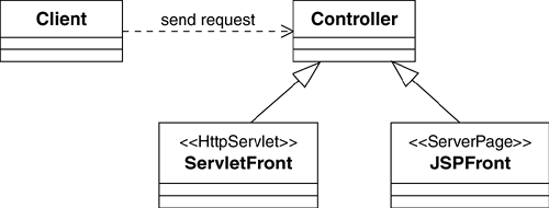
Presentation Request Processing is a mechanism that ensures that we handle the user requests coming to the system over the Web in a consistent way. The Front Controller J2EE design pattern (Alur et al. 2001) provides us with a design alternative, which is shown in Figure 8.4[2].
This design alternative recommends that all user requests come to a single element (the Controller). It is the responsibility of the Controller to determine if a request is legal before it is processed. As shown in Figure 8.4, there are two implementation strategies that we need to consider: (1) implement the controller as a servlet («HttpServlet») or (2) implement the controller as a JSP («ServerPage»).
These two examples illustrate that there are usually different alternatives for how we can design and implement a mechanism. In order to choose between those alternatives, we inventory (make a list of) them. RUP refers to the design alternatives as Design Mechanisms and the implementation alternatives as Implementation Mechanisms. Table 8.2 summarizes some of the alternatives we considered for the Online Auction application.
It is hard to give a general set of rules for selecting a design and an implementation mechanism from those identified in the previous step. Some choices may be obvious, while others may not. Some may be relatively equivalent, while others may have more far-reaching implications. For example, selection of the Front Controller J2EE design pattern to handle Web requests has many implications. One of them illustrates, that design and implementation mechanism choices are not independent. As we briefly discuss in Table 8.3, the choice of how to handle the user's presentation requests in the Web container influences the choice of how to handle user-session persistency. If you are the Software Architect, it is your responsibility to make these selections. Table 8.3 shows the choices we made for our Online Auction application (we only list the mechanisms for which we identified multiple design and implementation alternatives).
Table 8.2. Design and Implementation Mechanisms
| Analysis Mechanism | Design Mechanism | Implementation Mechanism |
|---|---|---|
| Authentication | Based on password and user ID | The application authenticates the user ID and password against those stored with the relevant user account. |
| Authorization | Security role-based authorization Use case-based authorization | J2EE-provided security mechanism. The application verifies that a specific user can perform a use case. |
| Messaging | Mail-based | Java Mail API. |
| Persistency (user session) | Container-managed session state | HTTP session managed by the Web container. Stateful session EJB managed by the EJB container. |
| Persistency (application) | Container-managed persistence (CMP) Bean-managed persistence (BMP) | J2EE-provided mechanism. JDBC API. |
| Presentation Request Processing | Front Controller J2EE design pattern | The controller implemented as a servlet. The controller implemented as a JSP. |
| System Parameter Management | Parameters are stored externally and read by the system | Parameters are stored in an XML file and internalized once when the application starts up. Parameters are stored in a database and are retrieved when needed. |
Table 8.3. Mechanism Choices
| Mechanism | Choice/Justification |
|---|---|
| Authorization | We decided to use a simple combination of the use case and security-based authorization. Upon authentication, the user session is assigned a security role. User requests always pass a use-case name as a parameter identifying the use case that is to be executed. If the use case requires authorization, the application checks a list (defined as a system parameter) to see if the security role is permitted to execute the use case. This approach supports the addition of new use cases without requiring changes to the authentication code. |
| Persistency (user session) | We decided to store the user session state in the HTTP session in the Web container. This decision requires some explanation, as it is an example of how differ- ent design activities influence each other. As we discuss in the Identify Design Elements activity, we have chosen to handle the use-case flow of control in the Web container. Since the system element that controls the use-case flow needs access to the session state, for simplicity and perform- ance reasons, the session state is also stored in the Web container. |
| Persistence (application) | We decided to only use CMP. In general, we believe that BMP should only be used when entities cannot be mapped into a database using the container-provided service. In a more complex application, the choice between BMP and CMP may have to be made at the entity level; however, the information model of our example application is not complicated and CMP is both adequate and convenient. |
| Presentation Request Processing | We decided to adopt the Front Controller J2EE design pattern and implement the controller as a servlet. The main function of the controller is to authorize and dispatch user re- quests. This function is better encoded in a servlet than a JSP. |
| System Parameter Management | We decided to store system parameters in an XML file and internalize them into an in-memory data structure at application startup. The decision was mainly driven by usability concerns; it is much easier to change the content and the structure of an XML file than a database. |
The results of this activity, such as Table 8.3, which documents the choice of mechanisms, should be captured in the Software Architecture Document[3]. Details, such as sample interaction diagrams, usage rules, information about the participants, common parameters, and so on, should be documented in the Design Guidelines.
If there is one activity that has the most impact on the system design, this is it. At the completion of this activity we should have identified the core system design elements.
Design Classes (servlets, JSPs and Java classes), whose structure and use are defined by the Java language, HTML and JavaScript
Framework Components (EJBs), whose structure and use are defined by the EJB container specification
Design Subsystems, which represent collections of related elements that should be designed, implemented and deployed as a unit
Interfaces, to represent abstract declarations of responsibilities provided by a Design Class, Framework Component or Design Subsystem
While performing this activity, keep in mind that the objective is to identify the design elements, not to refine their design. The refinement is performed in the activities of the Detail the Design workflow detail.
We cannot perform this activity without common principles that guide us through the process of deriving the design elements from the analysis elements. These principles should be identified early in the project's life cycle, captured in the Design Guidelines, and continuously refined as the design progresses.
Let's therefore, as an example, begin with an overview of the principles that have guided us through the design of the Online Auction application. These principles, which we believe are general enough to be applicable to a large family of systems, are based on:
The use of J2EE design patterns (Alur et al. 2001) and the implied separation of the different responsibilities of the application
Enterprise component design principles described in (Cheesman and Daniels 2001)
Best practices of developing business components[4] described in (Herzum and Sims 2000)
As we discussed in Chapter 7, we divided the Design Model of our Online Auction application into three layers: Presentation, Business, and Integration.
We organized the Presentation layer following a design refinement of the Presentation Request Processing mechanism discussed earlier. This refinement is based on the Service to Worker J2EE pattern (Alur et al. 2001). The pattern integrates two other patterns, the Front Controller and the Composite View, and adds dispatcher classes, view classes, and helper classes to the front controller class. The structure and participants of the refined mechanism are shown in the class diagram in Figure 8.5.
We summarize the roles of the participants in the following list.
All requests from a user (represented by the Client element) are handled by the FrontController servlet.
The FrontController delegates the processing of a request to a particular UseCaseDispatcher Java class. Each UseCaseDispatcher is responsible for handling all steps of a Use Case and hence understands the use-case flow of events.
A UseCaseDispatcher delegates the tasks of screen building to views that are implemented as JSPs (CompositeViewTemplate and CompositeViewElement). The views are organized by following the Composite View pattern, which we discuss in more detail in the step Identify Design Classes.
Views don't communicate directly with elements in the Business layer—this is the responsibility of each UseCaseDispatcher. If business data needs be displayed to the user, the data is obtained by a UseCaseDispatcher, through the use of a BusinessDelegate helper Java class, and then passed to views that build screens.
We decided to organize the Business layer of the system as a set of Design Subsystems that we stereotype «EnterpriseComponent»s. An enterprise component is similar to a “business component” as described by Peter Herzum and Oliver Sims (Herzum and Sims 2000) and a “component” as described by John Cheesman and John Daniels (Cheesman and Daniels 2001). It is a software implementation of a business concept or business process. It is a collection of related elements that should be a unit of design, implementation and deployment. We represent enterprise components as Design Subsystems for the following reasons.
An enterprise component's elements and the internal collaborations of those elements are completely hidden behind one or more Interfaces.
From the outside, an enterprise component is a single model element that collaborates with other model elements to fulfill its responsibilities. The description of an enterprise component's externally visible Interfaces and dependencies form its specification.
On the inside, an enterprise component is implemented by the design elements that realize the enterprise component's specification.
Well-designed enterprise components have one more important property, which is that each enterprise component should manage a disjoint part of the system's state. This property greatly improves system maintainability and ease of testing.
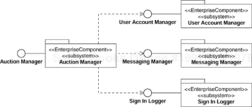
We will discuss shortly how we have identified the enterprise components shown in Figure 8.6. In the meantime, the figure is an example of the external perspective of the Auction Manager enterprise component from our Online Auction application. The specification of the Auction Manager enterprise component states that it provides the Auction Manager Interface and requires the User Account Manager Interface. We can also see that the User Account Manager Interface is provided by the User Account Manager enterprise component.
We decided to organize the internal structure and control access to our enterprise components, following a combination of four Sun J2EE design patterns (Alur et al. 2001): Business Delegate, Service Locator, Session Façade and Value Object. We show the participants of this composite pattern in Figure 8.7. To provide a more complete picture of the patterns used in the Online Auction application, we also included the elements of the presentation request processing mechanism in the figure.
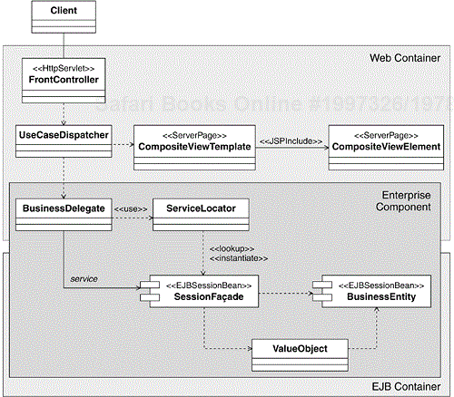
Figure 8.7. An Internal Perspective of an Enterprise Component and Allocation of Its Design Elements to Containers
It is interesting to notice, that although all design elements of an enterprise component belong to the Business layer of the system, some of them (BusinessDelegate and ServiceLocator in Figure 8.7) execute in a Web container, whereas the others execute in an EJB container. Also, from an internal perspective, a business delegate is a client's proxy for the enterprise component. We shall discuss business delegates in more detail shortly.
The design structure in Figure 8.7 implies a number of important design decisions:
The central element of an enterprise component is a façade session EJB (SessionFaçade in the figure). The façade realizes the Interface of the enterprise component, supports container-managed transactions, and prevents direct access to system resources.
Clients access an enterprise component via one or more business delegate(s)[5] (BusinessDelegate in the figure). Business delegates use service locators (ServiceLocator in the figure) to find and instantiate session façades. We use the service locator to hide platform and technology-specific details such as the use of JNDI and object creation.
An enterprise component manages a collection of entity EJBs (BusinessEntity in the figure).
Enterprise components don't pass references to the entity EJBs they manage. They only pass the state of the EJBs using value objects (ValueObject in the figure).
As you can see from looking at Figure 8.7, we use business delegates as the “connection points” between the Presentation and the Business layers of the system. When a use-case dispatcher creates an instance of a business delegate, it is essentially creating a proxy of an instance of an enterprise component.
The design structures of the Presentation and Business layers described above are the architectural foundation of our Online Auction application. Each project needs an architecture that guides us through the steps of the Identify Design Elements activity. If you are the Software Architect, it is your responsibility to define that architecture and to capture the design mechanisms and implied design principles in the Design Guidelines (see previous activity, Identify Design Mechanisms). Before we move to the discussion of the steps of the Identify Design Elements activity, we need to make one more important point about different granularities of design elements. We will be identifying design elements at three levels of granularity described in the following list and shown in Figure 8.8.
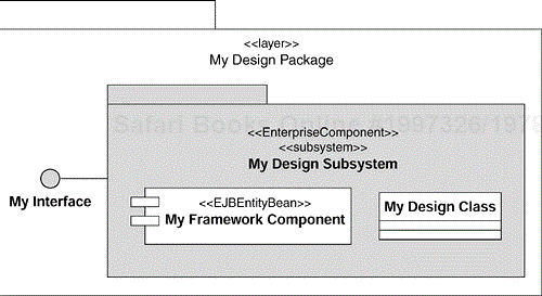
The largest element is a Design Subsystem that exposes one or more Interfaces. We use Design Subsystems to represent enterprise components. A Design Subsystem is represented in UML as a subsystem.
The next smaller element is a Framework Component, which we use to represent EJBs. A Framework Component is represented in UML as a component.
The smallest design element we consider is a Design Class (together with its attributes, operations and relationships), which is used to represent servlets, JSPs, and Java classes. A Design Class is represented in UML as a class.
To manage the design elements, we group them in Design Packages as shown in Figure 8.8. The top-level packages in the Design Model are stereotyped as «layer». We discussed layers in Chapter 7.
We are now ready to discuss the steps of the Identify Design Elements activity and illustrate them with examples. We will start by identifying the largest granularity elements first (the Design Subsystems) because they define the core of the logical structure of the system and they are composed of the smaller granularity elements (the Framework Components and the Design Classes).
Within our architecture, Design Subsystems are used to represent enterprise components. We use enterprise components to encapsulate business behavior as well as access to, and the management of, system data. The best place to start looking for the application's enterprise components is the set of Analysis Classes (control, boundary, and entity classes) that were identified during the Use-Case Analysis activity.
Some general guidelines for identifying enterprise components are as follows.
Divide the entity classes into groups such that members of a group can be managed together by a separate enterprise component.
Look at analysis-level realizations of interrelated Use Cases. In particular, look for and group similar responsibilities of the control Analysis Classes participating in those realizations. There is a good chance that similar (or related) responsibilities should belong to the same enterprise component.
Group related responsibilities that involve the same group of entity classes identified in the first bullet. If an enterprise component is to manage a set of entities, the responsibilities involving manipulating those entities should belong to that component.
Each group of responsibilities that we identify by following the above guidelines becomes a base from which we can derive the Interface of an enterprise component. As we work through the above steps, we should start putting information into the Design Model, as described here.
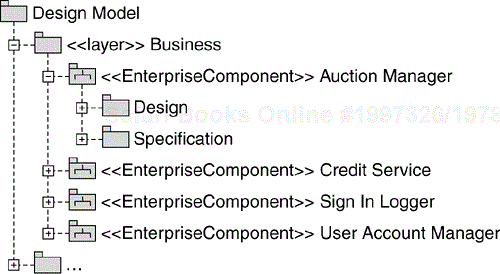
For each group of identified responsibilities, create a subsystem stereotyped as «EnterpriseComponent» in the Business layer of the Design Model.
In each subsystem, create a package named “Design”. This package will contain the design elements that will compose the enterprise component.
In each subsystem, create a package named “Specification”. This package will contain a description of the enterprise component Interface.
Then, create an Interface in the Specification package of each enterprise component that has the same name as the enterprise component.
Finally, capture the identified responsibilities of the enterprise components as operations on their Interfaces.
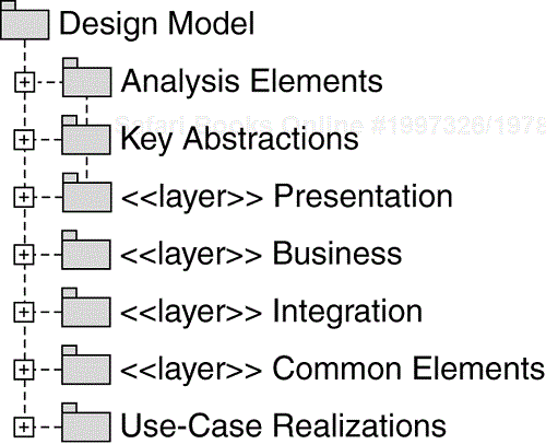
Let's illustrate the process with an example. During the Architectural Analysis activity, we defined the key abstractions of our Online Auction application, and we put them in the “Key Abstractions” package of the Design Model as shown in Figure 8.9. Unlike other Analysis Classes that we don't intend to maintain after they have been used to identify and define the design elements, we will keep the key abstractions as the base of the system's information model.
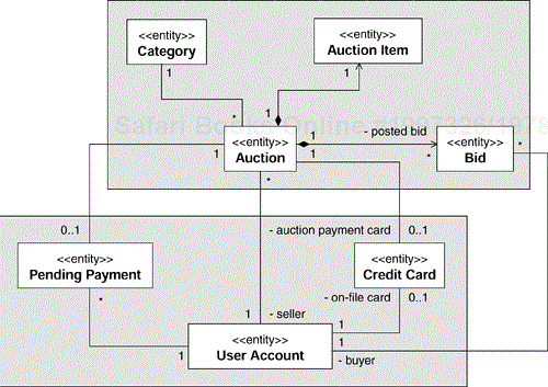
The key abstractions we have identified are shown in Figure 8.10.
We have divided the entities into two groups:
A group that has to do with user account, credit, and payment informa- tion. This group includes User Account, Credit Card, and Pending Payment entities.
A group that has to do with auctions and bidding. This group includes Auction, Auction Item, Bid, and Category entities.
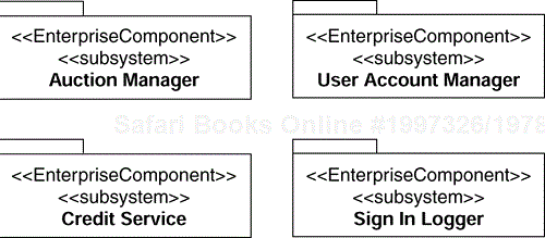
Our initial design assumption is that we will have an enterprise component that manages each group. We name these components User Account Manager and Auction Manager as we show in Figure 8.11. We will discuss the other two components, Credit Service and Sign In Logger, shortly.
We show the resulting organization of the Design Model[7] in Figure 8.12. The newly identified enterprise components reside in the Business layer of the model.
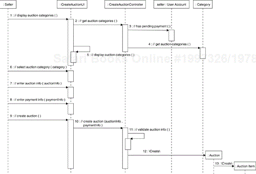
Now we need to look at the analysis Use-Case Realizations to come up with groups of responsibilities, which will become the first approximation of the Interfaces of the enterprise components. Let's consider the Auction Manager enterprise component. This enterprise component will be involved in the realization of the auction-related Use Cases (Create Auction, Browse Auction Catalog, Place Bid and Close Auction). In Figure 8.13 we show a sequence diagram of the Create Auction Use Case basic flow of events. We captured the sequence during analysis.
The place to look for the responsibilities of enterprise components, is the methods of the controller Analysis Classes. The sequence in Figure 8.13 shows two responsibilities that the Auction Manager enterprise component will have to fulfill (see the messages to the CreateAuctionController instance):
Obtain all auction categories so they can be displayed to the user (the //get auction categories message)
Create the auction and its associated auction item information (the //create auction message) which includes validating the auctioninformation
It is important to notice that the CreateAuctionController communicates with the User Account entity to see if the seller has pending payments. Since the entity is not in the group of entities managed by the Auction Manager enterprise component (see Figure 8.10), we assume that the //has pending payment message in Figure 8.13 represents a responsibility of the User Account Manager enterprise component.
After looking at the basic and alternative flows of the Create Auction, Browse Auction Catalog, Place Bid, and Close Auction Use Cases, and also at the requests to the Auction Manager from other Use Cases, we have arrived at the initial set of Auction Manager enterprise component responsibilities shown in Table 8.4. For clarity, we have grouped similar responsibilities.
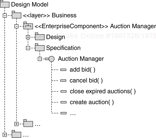
The last step of identifying an enterprise component is placing its initial Interface description in the Design Model. The result is shown in Figure 8.14. We have created an Interface that has the same name as the enterprise component, and that has an operation defined for each responsibility of the enterprise component. These operations are revisited in the Detail the Design workflow detail.
There are two other enterprise components in Figure 8.11. The Credit Service component is an example of a boundary analysis class representing an external system that evolved into an enterprise component during design. This happens if a boundary class handles nontrivial connection logic. For example, elements of our system may issue concurrent requests to an external system, but that system may be able to process them only sequentially. In such a case, it will be the responsibility of such a “boundary” enterprise component to queue the requests, invoke the service sequentially and then return the results to the appropriate clients. The Credit Service component is used by the Auction Manager enterprise component to charge the Seller a transaction fee when his or her auction is closed with a winning bid.
Table 8.4. Responsibilities of the Auction Manager Enterprise Component
| Group | Responsibility |
|---|---|
| Auction-related responsibilities | create auction set auction values close expired auctions get open auction for category get open auctions for user |
| Bid-related responsibilities | add bid cancel bid get highest auction bid get auction bids |
| Auction item-related responsibilities | get item get minimum bid value set item values |
| Auction category-related responsibilities | get auction categories get categories with open auctions |
The Sign In Logger enterprise component, also shown in Figure 8.11, is used by the User Account Manager component during the sign-in process to log who has signed into the system and when they signed in.
The following list gives a few simple and useful checkpoints for evaluating the result of the Identify Design Subsystems and Their Interfaces step.
Enterprise components should have balanced responsibilities. A single enterprise component should not be “doing it all.”
An enterprise component should have consistent responsibilities. When an enterprise component's responsibilities are disjoint, it should be split into two or more enterprise components.
An enterprise component should manage a disjoint section of the system's information model (should be responsible for managing a subset of the system state).
There should not be two enterprise components with identical or very similar responsibilities.
Looking at the above checkpoints and at the Table 8.4, you may be asking if we should have one Auction Manager enterprise component or four smaller components each responsible for one identified group of responsibilities. We have decided to have one component mainly because of its relatively small size.
As we explained earlier when discussing the granularity of the design elements, in our architecture, Framework Components represent EJBs.
Our architecture provides heuristics for identifying entity and session EJBs associated with enterprise components. The heuristics we used are summarized below.
For each enterprise component:
Create a session EJB that will fulfill the role of the component's session façade (SessionFaçade in Figure 8.7).
Create entity EJBs to represent the key abstractions managed by the component. Recall that we used groupings of key abstractions to identify the enterprise components and their responsibilities. Now we simply create entity EJBs to represent those key abstractions. Although we could consider representing each entity class in our key abstractions model as an entity EJB, we should consider grouping multiple entities into a single EJB to increase their granularity (see the example below).
Populate each entity EJB's implementation class and remote (or local) Interface with the attributes identified during analysis and define its primary key class.
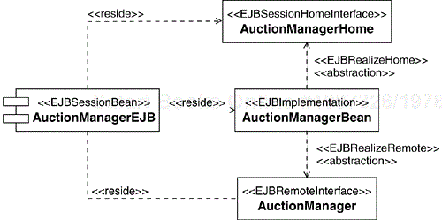
Let's illustrate the process using the Auction Manager enterprise component as an example. For this component, we create a façade session EJB called AuctionManagerEJB. Figure 8.15 shows the UML representation of this EJB. We represent EJBs as UML components with an appropriate stereotype (such as «EJBEntityBean» or «EJBSessionBean»)[8]. Entity and Session EJBs expose both a home and a remote Interface, which we represent as UML classes[9] with the appropriate stereotypes applied. The bean implementation class has the stereotype «EJBImplementation». The «reside» dependency is drawn between the UML component and the classes that comprise the EJB.
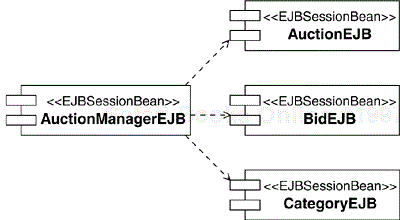
If you go back to Figure 8.10, you will see that we decided that the Auction Manager enterprise component should manage four entities: Auction, Auction Item, Bid, and Category. We could represent each entity as a separate entity EJB, but we know that each Auction always contains one and only one Auction Item. Hence we have decided to put both entities into one entity EJB (AuctionEJB) that will store both auction and auction item information. The EJBs we have identified are shown in Figure 8.16.
Let's also make an assumption that the Auction, Bid and Category entity EJBs will always run in the same container as the associated AuctionManager session EJB. As a result, the EJBs provide local (rather than remote) EJB interfaces, as described in Chapter 2, An Introduction to the Java 2 Platform, Enterprise Edition.
The resulting Design Model structure we use to capture the identified Framework Components is shown in Figure 8.17. As you can see, we place all elements associated with a particular EJB in the same package.
This is the last step of the Identify Design Elements activity. We showed how to identify the Design Subsystems (the enterprise components) and the Framework Components (the EJBs). What is left is to identify Design Classes. As before, our architecture greatly simplifies that task. If you look at Figure 8.7, you can see that there are only a few kinds of Design Classes in our architecture:
A front controller servlet
Use-case dispatcher Java classes
View JSPs
Business delegate Java classes
Service locator Java classes
Value object Java classes
We can defer the discovery of any other classes, such as additional “helpers,” until detailed design and implementation.
Let's start from the Presentation layer. We know that we have only one front controller in the system, so we create a class PresentationRequestController, stereotyped as «HttpServlet». We place it in a “Common Elements” package in the Presentation layer package of the Design Model. Now, for each Use Case we do the following (see Figure 8.7 for reference):
Create a Java class for the use-case dispatcher.
Create a class stereotyped «ServerPage» for each unique Screen in the associated Use-Case Storyboard of the User-Experience Model.
Place these classes in the Presentation layer package of the Design Model. We recommend dividing the Presentation layer package into subpackages to group elements that belong to related sets of Use Cases. In the case of our Online Auction application, we created two such subpackages; one for Auction Management and the other for User Account Management. We placed elements that are not specific to a Use Case in the Common Elements package (as we did for the PresentationRequestController servlet).
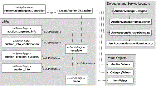
The results of applying the above rules for the Create Auction Use Case are shown in a fragment of the Design Model shown in Figure 8.18.
The CreateAuctionDispatcher class is the use-case dispatcher, and the auction_create_success, auction_info, and auction_info_confirmation server pages are associated with the Screens from the Create Auction Use-Case Storyboard.
We now consider the Design Classes in the Business layer. Following our architectural guidelines we can identify some of the key classes that will be part of the identified enterprise components. For each enterprise component we do the following (see Figure 8.7 as a reference):
Create a Java class for the enterprise component business delegate[10]
Create a Java class for the service locator that provides access to the session façade EJB of the component
For each entity EJB managed by the component:
Create a Java class to pass entity attributes by value (that is, a class that conforms to the Value Object J2EE design pattern).
If the entity EJB represents a composition, such as the Auction and Auction Item, you may need to create a Java class to pass the values of the composition as well as classes to pass the values of its individual parts.
The results of applying the above rules to the Auction Manager enterprise component are shown in a fragment of the Design Model in Figure 8.19. The AuctionManagerDelegate and the AuctionManagerHomeLocator classes are the component's business delegate and service locator classes, respectively. The AuctionValues and ItemValues classes are used to pass the entity EJB values to the clients of the enterprise component.
In Figure 8.20 we show another view of the identified classes. It is a view from the perspective of a particular Use Case and can be thought of as an instantiation of the patterns shown in Figure 8.7. All classes in Figure 8.20 participate in the Create Auction Use Case. We will discuss use-case participants and interactions between them in more detail in the Use Case Design activity of the Detail the Design workflow detail.
At that beginning of describing this activity, we mentioned that we decided to use the Composite View pattern to organize the view classes (see Figure 8.5). We can now explain this in more detail. The essence of the pattern is that use-case dispatchers always call the same JSP (the CompositeView Template in Figure 8.5 and the template JSP in Figure 8.20). This JSP provides the overall look and feel of the site[11] and includes other JSPs such as menus and use-case-specific pages. Some of these view classes are included statically, such as the menu JSP in Figure 8.20 to build the “standard” page elements such as the menus, header, and footer. Others JSPs can be included at runtime, like all other JSPs in Figure 8.20. These view classes build the “dynamic” elements of pages.
This concludes the steps of the Identify Design Elements activity. We have spent a disproportionate amount of time describing this activity, but we believe we have done that for some very good reasons, which we summarize here.
This activity, together with the mechanisms and guidelines provided by the Identify Design Mechanisms activity, forms a “bridge” between analysis and design.
The quality of the results of this activity determines the quality of the system design.
At the conclusion of this activity, we should have identified and described all key design elements of the system and the relationships between them. Any additional design elements should be of a secondary, or supportive, nature and should be discovered during detailed design and implementation. Discovery of major design elements late in the project's life cycle indicates a flaw in requirements, analysis, or the discussed aspects of design.
Before we move on, we would like to make a couple of important points. While performing this activity, it is important to maintain a delicate balance between identifying design elements and refining their design. This activity should focus on identifying the elements. The activities of the Detail the Design workflow detail focus on refining their design.
We would also like to emphasize that, in reality, the steps for identifying the design elements are performed concurrently. There is no rule that enterprise components must be identified before Presentation layer classes are identified. On the other hand, there are obvious sequential dependencies. For example, we cannot identify facade session EJBs until we know what enterprise components we have in the system.
Organizations that build similar systems often have software assets that can be reused during development of a new system. There may also exist assets that can be purchased or obtained from sources such as tools or infrastructure providers, community Web sites, public exchanges, and so on.
An asset is an artifact or a set of artifacts that have been developed with an explicit purpose of being reused on multiple projects. Assets can range from requirements statements through patterns and mechanisms to finished components.
Reuse is a tricky business. We all practice what is referred to as “ad hoc reuse.” We reuse classes that have worked for us before, we reuse design structures and parts of examples we find in books and on the Internet, and so on. Very few of us, however, practice “systematic reuse,” which is the development and reuse of assets that have been systematically designed, built and packaged for use on multiple projects.
As we mentioned, the concept of assets covers a potentially broad spectrum of artifacts. In this activity, we concentrate on the identification of reusable Design Subsystems (enterprise components) and Framework Components (EJBs). We assume that reuse of mechanisms has been considered in the previously discussed Identify Design Mechanisms activity. We also assume that use of large-granularity external subsystems, like the credit service enterprise component in our case, have been captured in the form of boundary classes during analysis and have already evolved into Design Subsystems, Frameworks Components, or Design Classes.
By presenting this activity after the Identify Design Elements activity, we may be giving a wrong impression that these two activities should be performed sequentially. In reality, these two activities are quite interconnected and should be performed concurrently. For example, if one of the non-functional requirements of the system is that it be based on a set of existing assets, then the Incorporate Existing Design Elements activity is performed in the early iterations of the project, possibly as early as in the Inception phase, in order to incorporate those assets.
We start by looking for design elements, such as enterprise components and EJBs, that offer Interfaces similar to the candidate Interfaces identified in the design. We should look for similar responsibilities, attributes, parameters and return values. Even if there is not an exact match, there may be opportunities to make minor changes to the design of the system that will allow the reuse of an identified component. Simple changes include rearranging or adding parameters to an Interface or refactoring the Interface by splitting it into several Interfaces, one or more of which match those of the existing component. When we identify a reuse candidate, we need to consider its non-functional properties, as well as its functionality. For example performance, security or cost of a component may disqualify it from being reused despite an otherwise perfect match of its Interfaces.
In our Online Auction application, the User Account Management enterprise component would be a good candidate for being implemented by an existing reusable component. User account management is a rather common function and there are commercially available components that could be considered as candidates. Were we building a commercial auction system, we would have seriously considered acquiring the User Account Management enterprise component from a third party rather than building it ourselves.
If reuse of an existing Design Subsystem or Framework Component in its entirety is not possible, we may still consider reusing one or more of its parts. This is more ad hoc than systematic reuse, but is a viable option as software round-trip-engineering tools have become quite sophisticated. Some of these tools can reverse-engineer Java classes, JSPs, deployment descriptors and database schemas. They can also generate the implementation from the design elements.
Databases, and the data residing in them, represent an important source of reusable assets. For example, reverse-engineering a database schema is an excellent first step in identifying what information used by the application already resides in existing databases. The set of Design Classes that result from such reengineering can be then mapped into the entity EJBs and/or types identified in the Identify Design Elements activity.
As we decide to incorporate existing elements in our design, we need to account for them in the Design Model. The extent of the model changes may vary. On the one hand we may modify a candidate Interface of a Design Subsystem to allow for reuse of an existing, functionally similar component. This will not result in changes to the overall Design Model structure. On the other hand, we may refactor an identified Design Subsystem into two Design Subsystems, one that will be reused and another that will still have to be developed. This will add a new Design Subsystem to the model structure.
Some systems are inherently distributed in that different physical nodes provide different services, which may give rise to concurrency. The J2EE platform has evolved to support enterprise distributed computing. The commercial implementations of the J2EE technologies not only provide interprocess communication, load balancing, and distributed resource management, but they also hide a lot of the gory details of using those capabilities. Leading implementations provide scalability and load balancing out of the box. This means we don't have to do anything special to a system design to execute it on a cluster of nodes. The same modules are deployed to a load-balancing container that can run on multiple processes and nodes in a fashion that is transparent to the logic of the application.
However, “application concurrency” can also be introduced in systems that are not distributed for scalability and performance reasons. Application concurrency is a “designed-in” separation of the system's logic into concurrent threads of computation. Application concurrency goes hand in hand with application distribution. If a system runs on multiple nodes providing independent computational resources, the nodes can lend themselves to concurrently executing components. Addressing the concerns of application concurrency and distribution is the focus of this activity.
It is not our intention to provide an exhaustive or even thorough coverage of concurrency and distribution in J2EE. However, the steps described below should provide useful guidance on how to address the main concurrency and distribution issues encountered when designing a J2EE application.
In the context of J2EE, the concept of a “node” can be confusing. In RUP, a node represents a processing device, such as a server computer, to which elements can be deployed. However, as described in Chapter 2, we do not deploy elements directly to nodes for two reasons. The first is that we physically deploy J2EE modules, not the elements contained in those modules. The second is that we deploy to a container that executes on a particular node (a server), not to the node directly (containers can be considered “virtual nodes”).
It can be argued that describing the deployment of J2EE modules to containers is of little value because it is obvious that a WAR is deployed to a Web container, an EJB-JAR to an EJB container, and so on. However, there is value in describing the deployment of a system when there are explicit requirements that certain elements of the system reside on a node with specific characteristics (for example, a node that supports a database, or a node supporting a legacy system).
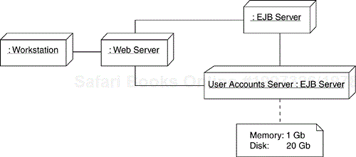
In cases like this, where there is value in articulating the physical distribution of the system, the first step is to show the distributed configuration of the nodes (and, optionally, the system resources allocated to each node[12]) in the Deployment Model. An example of a deployment diagram is shown in Figure 8.21. In this example, which is a refinement of the initial Deployment Model diagram from the Architectural Analysis activity, the database with user accounts and the components that access that data run on a specialized node (EJB server) identified as the “User Accounts Server.”
This step is a complement to the previous step. Having identified the nodes, we now need to decide which elements to deploy on them.
As described in Chapter 2, J2EE elements are packaged within J2EE modules, which are then deployed. Elements that need to run on a specific node must be packaged together in a separate J2EE module, and then that module is deployed only to that node.
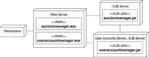
For example, if we know that the elements that access the user accounts database must be deployed to a separate node (the User Accounts Server shown in Figure 8.21), then these elements must be packaged in a separate J2EE module that is then deployed to the User Accounts Server. We illustrate such situation in Figure 8.22, where the useraccountmanager.jar file (which will contain the UserAccountManager EJB) is only deployed to the User Accounts Server node. We discuss J2EE modules in some more detail in Chapter 9.
Application concurrency is a term used to refer to the splitting of application logic into concurrent threads of execution in order to initiate multiple parallel activities. This is usually done for performance reasons. For example, this might allow an application to do useful work while waiting for a response from a slower legacy system. The purpose of this step is to analyze the application and identify opportunities for application concurrency.
The Online Auction application does not present many opportunities for application concurrency, because most of its operations are relatively simple and naturally sequential. However, the Close Auction Use Case presents some interesting possibilities. As first presented in Chapter 6, Requirements, the basic flow of the Close Auction Use Case is detailed in the following list.
The use case starts when the time for an auction to close has been reached.
The auction is marked as closed, so that no more bids are accepted.
The system collects the transaction fee from the Seller's account by submitting a payment request to the Credit Service Bureau.
The system sends an e-mail to the Buyer, notifying the Buyer that he or she is the auction winner.
The system sends an e-mail to the Seller, notifying the Seller that the auction has been closed and that a transaction fee has been debited from his or her account.
The use case ends.
Let's assume that auctions are closed on the hour. In a large auction system, many auctions may have to be closed at the same time. As we see from the Use Case flow, there are quite a number of bookkeeping operations that must be performed on each closed auction. On the other hand, we would like to close auctions instantaneously so we can stop the bidding. We can leverage concurrency to help us with this by following the algorithm described here.
Find the auctions that must be closed.
Mark each of these auctions as closed (by, for example, changing the value of their Status attribute to “closed”). This will make these auctions inaccessible for bidding.
Distribute the account charging and mailing operations on the closed auctions among a set of concurrently executing “bookkeeping” components (we briefly discuss one design strategy in the next step Identify Concurrency Mechanisms).
As we mentioned earlier, the concurrency associated with load balancing is supported by most J2EE platform implementations. However, application concurrency has to be supported by the application logic and hence needs to be designed. The objective of this step is to identify the mechanisms that will support application concurrency.
Application concurrency mechanisms are somewhat limited in the J2EE platform. In general, any Java class can create a new thread of execution. An EJB, however, cannot start, stop, suspend or resume a thread. This restriction is due to the fact that an EJB container must provide a predictable environment in which an EJB executes.
We can, however, make use of message-driven EJBs that can execute concurrently. Following our Close Auction processing example discussed in the previous step, we can create a queue that is processed by a number of concurrently executing message-driven EJBs. In this design the AuctionManager EJB is responsible for populating the queue (using the Java Messaging Service, JMS), and each of the message-driven EJBs is responsible for processing items on the queue by charging the Seller's account and e-mailing both the Buyer and the Seller.
Architectural flaws are known to be the hardest to fix and the most damaging in the long run. Detecting and fixing them early can save a lot of time later in the project. Detecting these flaws is a key objective of this activity.
We strongly advise that someone external to the project participate in the review of the architecture. A good review should examine multiple aspects of the system and include aspects often neglected such as system operations, administration and maintenance.
There are three major areas that the review should concentrate on:
The system artifacts, in particular the Software Architecture Document, the Design Guidelines and the Design Model. The reviewer should concentrate on the mechanisms, logical system structure, key design elements and their interactions, and the quality of the artifacts. The objective is to ensure that the architecture fits the system requirements, that it is not overdone or oversimplified, and that it addresses the recognized development risks. Additional potential design and requirements mismatches include unrealistic requirements or missing requirements.
The nonfunctional properties (or quality attributes) of the system. Architectural quality attributes, such as performance, reliability, ease of modification, security, or safety, are hard to measure. Only a few of them can be objectively measured. Performance is an example of an attribute where measurement is possible. Other attributes are more qualitative or subjective. The reviewer should start by making a list of the important properties, such as performance or security, together with the expected or desired values of these properties (both qualitative and quantitative). Next the reviewer should gather information about how the proposed architecture meets the described nonfunctional requirement. The very exercise of precisely specifying the system attributes and asking questions like “How have you achieved the response time below three seconds?” usually quickly reveals weak points of the architecture.
The exceptional or boundary conditions. The reviewer should start from preparing a list of questions that exemplify those exceptional situations such as “What happens with a user transaction when the user is disconnected from the system in the middle of the transaction?” or “How do you recover from the EJB server failure?” Then the reviewer should ask the Software Architect to walk him or her through scenarios, illustrating how the system architecture addresses these exceptional situations.
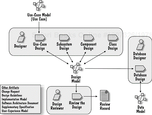
The Detail the Design workflow detail contains the activities shown in the Figure 8.23.
The objective of these activities is to refine the identified design elements by working out the details of their content, behavior and relationships. The refinement of a design stops when the element can be handed off for implementation[13].
The design activities of this workflow detail are organized around the type of design element they focus on.
Subsystem Design focuses on a Design Subsystem (enterprise components).
Component Design focuses on a Framework Component (EJB).
Class Design works on a Design Class (servlet, JSP, or Java class).
Database Design focuses on the Data Model elements (the database schema in particular).
These activities are highly interrelated and are often performed concurrently. For example, we cannot refine the design of an enterprise component without considering the design of the entity EJBs it manages. Similarly, we cannot finish the design of a use-case dispatcher class before we have fully defined the Interfaces of the enterprise components it uses.
The Use-Case Design activity brings all design elements together by analyzing how they collaborate to realize the system Use Cases.
As always, the workflow detail culminates with a review of the produced results.
The activities of this workflow detail don't have an implied sequence. For example, one could ask if Use-Case Design should happen first to make sure that the specifications of the design elements support the Use Cases before they are detailed or if Use-Case Design be done last to make sure that we did not miss anything. In reality, both of these approaches have some validity; however, we will start our discussion from the Use-Case Design activity because it unifies the other activities.
This activity is the design corollary of the Use-Case Analysis activity described in Chapter 7. The main difference is that in this activity we show how design elements, rather than Analysis Classes, collaborate to realize a Use Case. This activity therefore discusses the refinement of the analysis-level Use-Case Realizations created during analysis and results in design-level Use-Case Realizations.
In analysis we developed a Use-Case Realization that shows how Analysis Classes realize the Use Case. We represented the participants in the analysis-level Use-Case Realization on a class diagram. We also represented the realization of each flow of events on an interaction diagram (such as a sequence diagram). For example, the basic flow interaction diagram of the analysis-level Create Auction Use-Case Realization is shown in Figure 8.13.
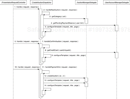
In design, we describe the realization of the Use Case in terms of the design elements identified in the Identify Design Elements activity. For example, Figure 8.20 depicts the participants of the Create Auction Use Case. In Figure 8.24, we describe how some of these participants interact to realize the Use Case functionality.
We have simplified both diagrams for readability without, we hope, obscuring the Use Case description. In the Participants diagram (shown in the model structure in Figure 8.20) we only show business delegates and locators of the enterprise components. As noted earlier, a business delegate provides a convenient representation of an enterprise component in that it exposes the interface to the enterprise component, but completely encapsulates its internals (a business delegate is a “smart proxy” for an enterprise component). Business delegates, therefore, allow us to create greatly simplified interaction diagrams when describing the realization of the flow of events of a Use Case. For example, in the sequence diagram shown in Figure 8.24, we don't describe the details of how the use-case dispatcher obtains an instance of the business delegates using the enterprise component service locator. We only show the use-case dispatcher communicating with the business delegate.
As we work through each analysis-level Use-Case Realization, we refine the design of the participating design elements and, in particular, we fully describe their operations.
The architecture and the mechanisms developed in the Refine the Architecture workflow greatly simplify the development of Use-Case Realizations. Because most of the Use-Case Realizations follow the same set of patterns and use a common set of mechanisms, their structure is similar to the one shown in Figure 8.24 and Figure 8.20.
By now we should have a design-level Use-Case Realization for each Use Case addressed in the current iteration. In this step, we reconcile the individual Use-Case Realizations and unify design elements by identifying:
Opportunities to unify design elements; that is, opportunities to replace a set of elements with overlapping responsibilities with one element that unifies all of them
Opportunities to abstract common behavior using inheritance or delegation between design elements
For example, in the Online Auction application, we recognized that all use-case dispatchers were performing integrity checks on the data input by the user. After closer examination, we decided to develop a generic input field validation mechanism. In order to simplify the code of the use-case dispatchers, we implemented the logic of the mechanism as a method on a DefaultDispatcher class, from which all of the use-case dispatchers inherit.
A Design Subsystem is a part of a system that encapsulates behavior, exposes its services through a set of Interfaces, and packages other model elements. In our architecture, we use Design Subsystems to represent enterprise components, which implement a business concept or a set of business responsibilities and manage a disjoint portion of the system state.
The initial description of an enterprise component includes a candidate Interface, a number of Framework Components (a façade session EJB and a set of entity EJBs), and a number of Design Classes (candidate value objects, a business delegate and a service locator). The detailed design of these design elements must be completed before we can implement the enterprise component (see Chapter 9).
We have identified candidate Interfaces of the enterprise components in the Identify Design Elements activity (see Table 8.4). Now, during detailed design of the enterprise component, these initial candidate Interfaces are refined into concrete Interfaces. The consistency and completeness of these Interfaces is verified in the Use-Case Design activity, where the enterprise component interactions with other system elements are put together and reviewed.
The key property of an enterprise component is that it is fully described by its Interface. In our architecture, the enterprise component's business delegate class realizes this Interface. In most cases, the same Interface is also realized by the session façade of the enterprise component and the business delegate simply exposes the business methods to the client (in this respect, it is a smart proxy of the session façade).
Each enterprise component Interface exposes a view of the system state that can be inspected and/or modified via that Interface. This view is referred to as the interface information model in (Cheesman and Daniels 2001). This information model does not have to be exactly equal to the sum of the entity EJBs managed by the enterprise component. This is because there may be information in the entities never exposed to the enterprise component clients directly. Conversely, the enterprise component may expose computed information that is not directly stored in its entities.
Given the discussion in the Identify Design Elements activity described earlier, we already have an initial draft of the elements of the Design Subsystems representing our enterprise component. We will now concentrate on the refinement of these design elements.
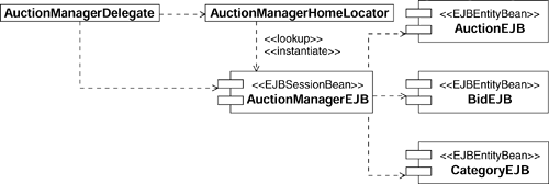
Consider, for example, the Auction Manager enterprise component shown in Figure 8.25. Following the pattern names discussed at the start of this chapter, the AuctionManagerDelegate Java class is the business delegate, the AuctionManagerHomeLocator class is the service locator, the AuctionManagerEJB component is the session façade, and the CategoryEJB, AuctionEJB and BidEJB components are business entities. From an “internal” perspective, we should expect to see these elements used when describing the subsystem's behavior.
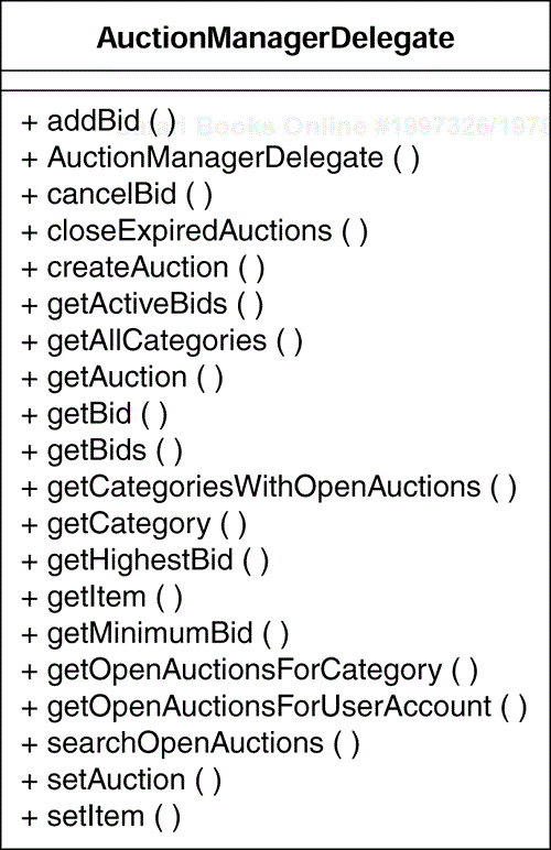
From an “external” perspective, the subsystem behavior is described by its Interface, which is realized in our architecture by the business delegate and the session façade. The operations that a business delegate must support were first identified during the Identify Design Elements activity as the business operations of an enterprise component's Interface. During the Use-Case Design activity these operations were further refined. Because business delegates realize their enterprise component's Interfaces, they can be conveniently used as an enterprise component proxy.
The business delegate of the Auction Manager enterprise component is shown in Figure 8.26.
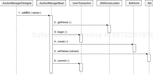
Each business service listed in an enterprise component's Interface is realized by a collaboration of its elements. Descriptions of these collaborations can be represented in the same way as the design element collaborations documented within the Use-Case Realizations in the Use-Case Design activity—as UML collaboration instances. If you choose to model the realization of an enterprise component's operation in terms of the interactions of its elements, define a collaboration instance for the operation, using the operation name as the collaboration instance name, and stereotype the collaboration instance «interface realization». Then define a sequence diagram that describes the collaboration among the subsystem elements when performing the operation. An example is shown in the sequence diagram in Figure 8.27. This diagram represents a collaboration of the elements of the Auction Manager enterprise component realizing the addBid operation. The UserTransaction object represents a transaction context and the two methods begin() and commit() demarcate the transaction boundaries. This object is a low-level helper class that we have included for completeness.
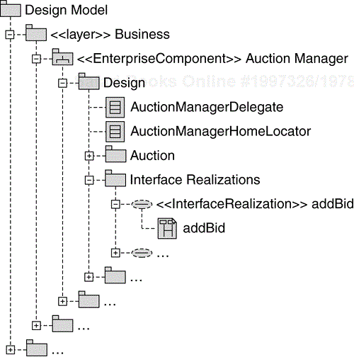
The Interface operation realizations are placed within the “Interface Realizations” subpackage of the enterprise component, as shown in Figure 8.28.
During the Subsystem Design activity, we make sure that all subsystem external dependencies are identified. Dependencies between enterprise components can be represented as dependencies between the Design Subsystems that represent the enterprise components and the Interfaces of the other enterprise components that the enterprise components are dependent on. An example from our Online Auction system is shown in Figure 8.29.
Design Subsystems should only depend on the Interfaces of other Design Subsystems and not on their internals. In the architecture of the Online Auction application, this means that an enterprise component should only depend on the business delegates of the enterprise components it depends on. This approach ensures that a subsystem is treated as a “black box” and, while its internal implementation may change, other components don't see that change as long as its external Interface stays the same.
As we discussed earlier, we use Framework Components to represent EJBs. We identified the EJBs in the Identify Design Elements activity. Then, in the Subsystem Design activity, we distributed the enterprise component responsibilities between its session and entity EJBs. In this activity, we refine the design of those EJBs to the point where they can be implemented.
As described in Chapter 2, an EJB comprises a number of elements. Specifically, all EJBs (with the exception of message-driven EJBs) have a home and remote Interface (or local home and local Interface), and an implementation class. Entity EJBs also have an associated primary key class.
The behavior of an EJB is characterized by the operations on its home and remote Interfaces. The purpose of this step is to specify how the EJB implementation class, and the elements it depends on, realizes these operations. We also need to specify any operations that the EJBs must implement in order to be managed by the container. For example, BMP entity EJBs must implement operations that store and restore their state.
In this step, we should also define the transactional properties of the EJBs.
We have already seen in Figure 8.15 how to model the structure of an EJB in UML. The elements that comprise an EJB are also grouped in a Design Package in the Design Model structure. We show a recommended model structure in Figure 8.17.
In the previous step, by defining the interactions of the EJB implementation classes, we may have identified specific dependencies of the EJB implementation classes on other design elements. In this step, we simply describe and document these dependencies for the team members that will be using and implementing them.
In this activity we refine the design of servlets, JSPs[14], and other Java classes. The objective of the activity is to ensure that the Design Classes provide the required behavior and that sufficient information is provided to unambiguously implement them.
Classes can be assigned a visibility with respect to the Design Package in which they reside. For example, a particular class may be considered “private” to the Design Package in which it resides, if it is only ever used by other elements inside that Design Package. Keep in mind that elements within a Design Subsystem are implicitly private and therefore don't need to be declared as having private visibility. In our architecture, the only public class shown in the enterprise component structure is the business delegate.
The majority of operations on classes are identified during the Use-Case Design, Subsystem Design and Component Design activities. However, we may not have identified all operations. For example, we may need additional operations to support:
Object creation
Object deletion
Object comparison (to test to see if two instances of a class are the same)
Object copy
Interaction with a supporting mechanism (such as garbage collection or “serialization” of an object into a data stream)
The naming conventions of the implementation language should be used when naming operations, return types, and parameters and their types. This naming convention should be described in the Design Guidelines.
We also identify the visibility of each operation as either public (the operation is visible outside of this class), protected (the operation is visible only to the class itself, or to its subclasses), or private (the operation is only visible to the class itself).
Finally, we may also identify operations that apply to the class as a whole, rather than each instance. In the Java programming language, these operations are identified using the “static” keyword. An example of such an operation is one that returns all instances of the class.
At this point, some of the attributes of the major design classes, especially those representing the key abstractions, may already be defined. However, this is where their signatures are refined. Also, during the definition of operations, we may identify additional attributes needed by the class in order to carry out the operations. For each attribute, we define characteristics such as its name, its type, any initial value, and its visibility (in terms of being private, protected, or public).
A class can also move through a number of states that affect the behavior of its operations. It is useful to consider representing these states using one or more attributes.
In this step we describe dependencies, associations and generalizations between classes.
A dependency should be added between two classes when one class needs to “use” the other. Dependencies are transient, existing only for a limited duration, and do not represent a structural relationship between classes. Class A depends on class B for reasons such as those in the following list.
An instance of class B is passed as a parameter in an operation of class A.
An instance of class B is passed as a return value from an operation of class A.
An instance of class B is used in the implementation of one of the operations of class A.
An association is a relationship between two classes that implies that instances of these classes have a structural relationship. We may also choose to refine an association and make it an aggregation relationship. An association between two classes can also be given a number of attributes such as:
Navigability (to show the direction of the association)
Multiplicity (to show how many instances of one class can be associated with one instance of the other class)
Association name
Role name (to name the role of the instances of a class in the association)
Classes may be organized into a generalization hierarchy to reflect common behavior and common structure. A common superclass can be defined, from which subclasses can inherit both behavior and structure.
When we find a generalization for two or more subclasses, we create a superclass to contain the common attributes, associations, aggregations, and operations. We then remove the common structure and behavior from the subclasses.
The entity EJBs are the primary means of realizing persistency in J2EE applications. However, those EJBs must use an underlying persistency technology to store their state. In the majority of cases, it is relational database technology. As shown in the Detail the Design workflow detail diagram in Figure 8.21, the design of the database is the responsibility of the Database Designer, not the Application Designer. However, the entity EJBs cannot be designed in isolation from the database design because these activities may affect each other.
If you remember from our earlier discussion, there are two options for persistency for entity EJBs: container-managed persistence (CMP) and bean-managed persistence (BMP). In this step, we consider each of these two cases.
The EJB container persists CMP entity EJBs in the tables of a relational database. In order to store the state of an entity EJB, the container has to be given a mapping between the EJB and a table, and between the bean attributes and the rows in the table. The Application Designer and the Database Designer have to ensure that these mappings are both type-compatible and semantically correct. They have to ensure that the database types can be properly converted to and from the Java types and that the table columns and entity attributes represent the same information. In the process of defining the table-to-EJB mapping, the design of both the tables and the EJBs may have to be adjusted.
Also, an entity EJB can provide any number of custom finder methods that are exposed on its home Interface. For each such method, there must be a query statement that is executed when the method is called. The finder query statements must be consistent with the schema of the underlying database. The mappings for CMP entity EJBs and the finder query statements are captured in the EJB deployment descriptors that were introduced in Chapter 2.
BMP entity EJBs store and retrieve their state themselves, and hence, they can use any storage mechanism. In practice, however, we most often use a relational database and then use JDBC to access it.
In general, you should use BMP entity EJBs only when the deployment tools cannot map the bean to a database table. This is because BMP entity EJBs are harder to maintain and are coupled to the underlying database schema.
If you are using a BMP entity EJB, you must provide:
Implementations of methods for loading, storing, and removing the EJB that will be called by the container
Implementations for the finder methods and create methods on the home interface that return instances of the primary key class
Because of their tight coupling with the underlying database, BMP entity EJB design cannot be done in isolation from the database design, even more so than the design of CMP entity EJBs.
Most databases support a stored procedure capability. A stored procedure runs within the process space of the database management system, and provides the ability to perform database-related actions on the server without having to transfer data across a network. Stored procedures usually come in two flavors: actual procedures and triggers.
Procedures are executed explicitly by an application and can return values. Triggers are invoked implicitly when some database event occurs (insert a row, update a row, delete a row, and so on), have no parameters (since they are invoked implicitly), and do not provide return values.
Because of their explicit invocation, procedures can only be used by BMP entity EJBs. Triggers, on the other hand, have general applicability. The use of stored procedures should be considered for performance reasons and carefullyexamined with the Database Designer. It is the responsibility of the Database Designer to write them and store them in the database system.
With each successive iteration more and more of the system design is detailed. However, before we proceed to implementation, we should review the detailed design to ensure that it meets the following criteria:
It fulfills the system's requirements.
It is consistent with the design guidelines.
It is detailed enough for implementation.
The review should concentrate on:
The design-level Use-Case Realizations developed in the iteration. Evaluate each Use-Case Realization to make sure that it implements the required system behavior and that the behavior has been distributed to the appropriate design elements.
The design elements detailed in the iteration. Examine the Interfaces of the Design Subsystems and Framework Components to make sure they provide the required services. For the Design Subsystems and Framework Components also make sure that the behavior they expose is realized by the collaboration of their elements.
As always, any defects identified during the review should be documented in Change Requests, and the responsibility for finding a resolution should be assigned to a member of the team.
In this chapter we discussed how to produce a detailed design of a system from the results of analysis that support the requirements. We began by identifying common design mechanisms that provide part of the architectural foundation of the system.
With architectural guidelines in hand, we proceeded to identify the design elements. We classified the elements according to their granularity from enterprise components, to EJBs to classes. We described an approach to identifying the enterprise components and their services using the key abstractions and the analysis-level Use-Case Realizations. Then we proceeded to identify the EJBs and classes, still closely following our architectural guidelines.
After identifying the design elements, we proceeded to refine their design. As in analysis, the Use Cases provided us with the convenient instrument for looking at and refining related sets of design elements to make sure that they collaborate to deliver the required system functionality.
We completed the design activities by refining and documenting the detailed designs of the individual elements.
Although we used our Online Auction application as an example throughout the chapter, we believe that the design process we described and the elements of the architecture we used are applicable to a large family of online enterprise systems.
Before we move on to discussing the implementation of the design, we want to emphasize again the iterative nature of the process we are presenting. The design is produced over a number of iterations. Design may start very early in the Inception phase with the selection of reusable components. It intensifies in the Elaboration phase, when the key system elements are designed, and may even be a part of late iterations of the Construction phase when peripheral system elements are completed.
[1] Key abstractions are also referred to as the Business Type Model or System Information Model.
[2] Throughout this book we are using slightly different class stereotypes than the ones used in (Alur et al. 2001). Our stereotypes are consistent with those in “Java Specification Request 26 UML Profile for EJB” (Java Community Process) and those used in RUP. In those cases where stereotype names are different, the differences are small and should not introduce any ambiguities.
[3] The structure and content of the Software Architecture Document are discussed in Appendix A, Describing a Software Architecture.
[4] Two authors of this book, Peter Eeles and Wojtek Kozaczynski, were members of SSA's DOCA development team where the business component concepts were refined and tested. Peter was the architect of the deployment infrastructure and Wojtek was the chief architect of the team.
[5] There is no guideline that states that an enterprise component should have only one associated business delegate. Usually a component must support a number of Use Cases and hence may have groups of responsibilities that it performs. It is up to the architect to decide if the groups should be “assigned” to multiple business delegates or one business delegate.
[6] This diagram is a slight simplification as the enterprise component Design Subsystem contains subpackages that contain the Framework Components and Design Classes.
[7] See Appendix B, Modeling Conventions for a summary of the model organization guidelines we follow in the book.
[8] The EJB UML representation is defined in “Java Specification Request 26 UML Profile for EJB” (Java Community Process).
[9] A Java interface is not modeled as a UML interface since it is not semantically equivalent. For example, a Java interface can have fields, whereas a UML interface cannot.
[10] As we noted earlier, for more complicated enterprise components we may create multiple business delegates.
[11] This is why sometimes the composite view template JSP is referred to as the “skin” server page of the site.
[12] See the UML note attached to the node in Figure 8.21.
[13] The hand-off should not be interpreted as passing the artifacts to another team or person, because in many cases the same person will do both the design and the implementation.
[14] Although JSPs are not Java classes, they can contain an arbitrary logic and we consider them in this activity.
[15] A Change Request is necessary because the design of the database may result in request for changes to the Design Model.


