
8
Forensic Imaging
One critical task that incident response analysts often must perform is imaging digital evidence. As we discussed in prior chapters, a great deal of evidence related to an incident can be found within log files, memory, and other areas and can be acquired relatively quickly. In some incidents, such as internal malicious activity (for example, fraud, industrial espionage, or data leakage), a more detailed search for evidence may be required. This evidence includes master file table entries, files, and specific user data that is contained on the hard drive of a suspect system. If incident response analysts encounter such circumstances, they will be required to obtain an image of a suspect drive. As with any aspect of digital forensics, obtaining a usable and court-defensible image depends on the appropriate tools, techniques, and documentation being used.
This chapter will explore the fundamental concepts of digital imaging and the preparation and tools that are needed to acquire a forensically sound image of a physical drive or another logical volume. More specifically, we will cover the following topics:
- Understanding forensic imaging
- Tools for imaging
- Preparing a staging drive
- Using write blockers
- Imaging techniques
While this chapter presents some very technical and process-driven material, it is important that responders understand imaging. This process is critical to producing images that can be relied on for root cause analysis (RCA) and potential courtroom use.
Understanding forensic imaging
Imaging a storage drive is a process where details matter. This section provides a solid foundation on forensic imaging, how it is accomplished, the various types of digital imaging processes, and the various proprietary file formats.
Having a solid understanding of the facets of forensic imaging is important for incident response analysts. Understanding the tools, techniques, and procedures involved ensures that evidence is handled properly and that analysts have confidence in the evidence they’ve acquired. In addition, understanding the necessary terminology allows analysts to accurately prepare reports and testify as to their findings if the need arises.
Image versus copy
One of the first concepts that should be understood is the difference between forensic imaging and copying. Copying files from a suspect hard drive or another medium only provides analysts with the actual data associated with that file. Imaging, on the other hand, allows the analyst to capture the entire drive. This includes areas such as slack space, unallocated space, and possibly accessing deleted files. Imaging also maintains metadata on the volume, including file timestamps. This becomes critical if a timeline analysis is conducted to determine when specific files were accessed or deleted.
Often, the terms cloning and imaging are utilized in place of each other. This is a common improper use of terminology in the IT realm. When cloning a drive, a one-to-one copy of the drive is made. This means that the drive can then be inserted into a system and booted. Cloning a drive is often done to make a fully functional backup of a critical drive. While a cloned drive contains all the necessary files, it is cumbersome to work with, especially with forensic tools. As a result, an image file is taken. An image of a drive contains all the necessary files; its configuration permits a detailed examination while utilizing forensic tools.
Logical versus physical volumes
The second concept that needs to be understood is the types of volumes that can be imaged. Volumes can be separated into physical or logical volumes. Physical volumes can be thought of as containing the entirety of a hard drive. This includes any partitions, as well as the master boot record (MBR). When imaging a physical volume, the analyst captures all of this data. In contrast, a logical volume is a part of the overall hard drive. For example, in a hard drive that is divided into the MBR and two partitions, a logical volume would be the D: drive. When imaging a logical volume, the analyst would only capture data contained within the D: drive.
The following diagram illustrates data that is captured while imaging either a physical or logical volume:
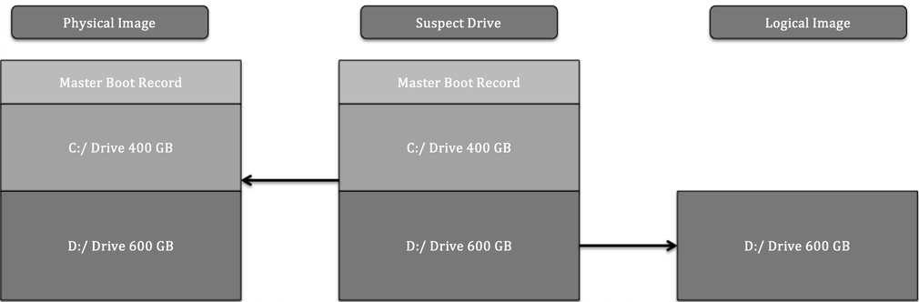
Figure 8.1 – Physical versus logical volumes
The type of incident that is being investigated largely dictates the type of imaging that is conducted. For example, if an analyst can identify a potentially malicious file being executed from the D: drive and is intent on only capturing that data, it might be faster to acquire a logical image of only that volume. Furthermore, a logical acquisition may be necessary in cases where Full Disk Encryption (FDE) is being used. Without the encryption key, logically acquiring files while the system is running is often the only option that’s available.
The one key drawback that a logical image has is that it will not capture unallocated data or data that is not part of the filesystem. Deleted files and other trace evidence will not be part of a logical image. In cases where an activity such as employee misconduct is suspected, the analyst will need to trace as much activity as possible, so a full image of the physical volume will be conducted. Time isn’t a necessary factor here.
In Chapter 5, we discussed the acquisition of evidence such as log files and running memory from a live or powered-up system. In much the same way, incident response analysts have the capability to obtain a logical volume from a running system. This technique is referred to as live imaging. Live imaging may be the best option if a potentially compromised system cannot be taken offline—say, in a high availability (HA) production server—and potential evidence is located within a logical volume.
Dead imaging is performed on a system that has been powered down and the hard drive removed. In this type of imaging, the analyst can capture the entire disk, including all the volumes and the MBR. This may become necessary in incidents where analysts want to ensure that they capture the entirety of the source evidence so that there is no location that hasn’t been examined.
Types of image files
Another aspect of forensic imaging that an analyst should have knowledge of is the types of image files that can be created and leveraged during an investigation. There are several types of image files, some of which are very specialized, but for the purposes of this book, we will focus on the three most common types of evidence files that analysts will most likely create and work with during an incident:
- Raw images: A raw image file contains only the data from the imaged volume. No additional data is provided in this type of image, although some imaging tools, such as FTK Imager, include a separate file with imaging information. Raw image outputs include the .raw, .img, and .dd extensions. Some software, such as the Linux dd command, provides a flexible option when speed and compatibility with forensic tools may be an issue.
- Advanced Forensics File Format (AFF4): AFF4 is an open source format for image files. First proposed in 2009, the format is used to support several tools, such as Google Rapid Response (GRR).
- EnCase evidence files: An EnCase evidence file, or E01 or EX01 file, is a proprietary file format that was developed by OpenText as part of its EnCase forensic tools in 1998. This format was based on the Expert Witness Format (EWF), which was found in ASR Data’s Expert Witness Compression Format. The E01 file contains metadata about the image. The metadata that is contained in both the header and footer captures and stores information about the drive type, operating system, and timestamps. Another key feature of an E01 file is the inclusion of a Cyclical Redundancy Check (CRC). This CRC is a file integrity verification that takes place after every 64 KB of data is written to the image file. The CRC ensures the integrity of the preceding block of data over the entire image file. Finally, an E01 file contains a Message Digest 5 (MD5) hash within the footer of the file. The following diagram illustrates which components of an E01 file are created during the imaging process:

Figure 8.2 – E01 file format
SSD versus HDD
Another key facet of imaging that incident response analysts need to understand is how to image specific storage media—specifically, understanding the difference between a hard disk drive (HDD) and a solid-state drive (SSD). Understanding this difference has become critical, with SSDs being much more common, especially in endpoints such as laptops and desktop computers.
The main difference between the two goes down to the smallest details of how information is stored. Traditional spinning HDDs store information by changing magnetic polarity on actual spinning disks. Therefore, digital forensic and incident response analysts need to be aware of magnetic fields when handling evidence and why dropping an HDD would often prove fatal for the disk.
The one aspect of HDDs that is of interest to digital forensic examiners is how data is handled. The data is written to the disk and stays within the sectors that have been assigned to the data. When a user deletes a file, it is not removed. The data may be complete or partially overwritten, and with proper imaging tools, this data can be located and reconstructed for analysis.
Because of how HDDs work and the potential for reconstruction of data, it is a good practice to create a physical disk image. This involves powering down the system by removing the source of power, not through the operating system shutdown. This preserves the state of the drive now the analyst has accessed it. In those circumstances where this is not possible, a logical image can be taken from a live and powered-up system.
SSDs, on the other hand, hold information based on the state of electrons in cells in the SSD. This type of data storage uses instructions found on the printed circuit board (PCB) that controls how data is handled on the SSD. The first set of instructions is garbage collection. When a user deletes a file, the operating system sends instructions to the chipset indicating that the file is marked for deletion, and the PCB can reset the electrons in that space to neutral, thereby removing the data. This operating system instruction is often referred to as TRIM. For example, entering the fsutil behavior query disabledeletenotify command into Windows’ Command Prompt will produce the following output if the OS is using an SSD:
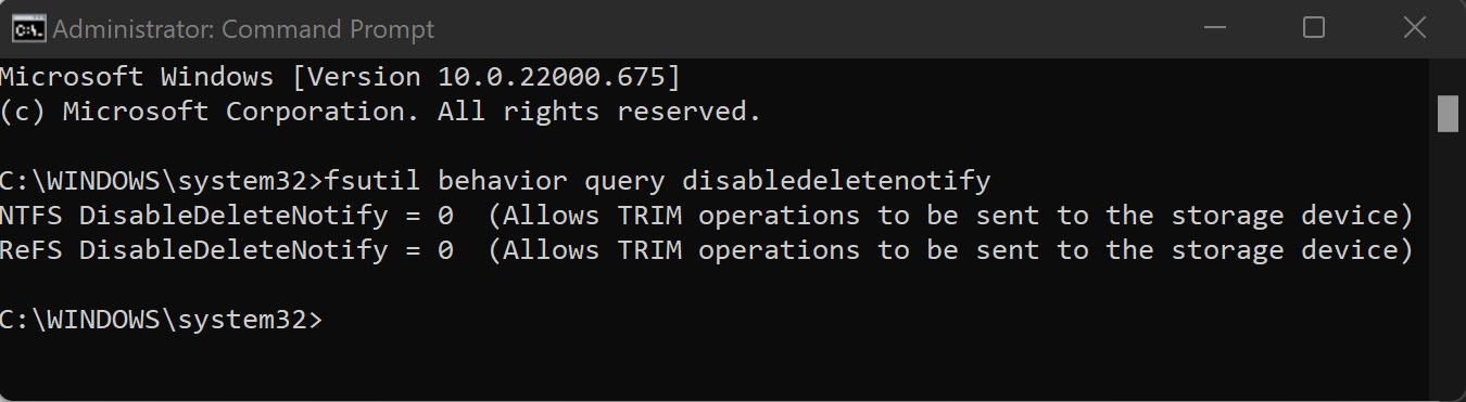
Figure 8.3 – TRIM operations enabled
Another feature of SSD chipsets that is of concern to digital forensic and incident response analysts is wear leveling. The electrons in an SSD have a finite lifespan and cannot be continually turned on and off. If the operating system only uses the first 100 GB of the drive, it may wear that section out, making the drive useless. To prevent this, SSDs make use of wear leveling, where data is continually moved to different locations on the drive, thereby reducing the potential of making the drive unusable.
These two features mean that traditional write blockers that are used to ensure that no changes are made to the disk during imaging do not work, as the PCB manages how data is written and leveled on the SSD. While imaging is possible, the analysts cannot ensure that no changes were made to the disk during the process. To limit these changes, analysts should image an SSD in the condition that they found it. If the system is powered off, remove the drive from the system and image. If the system is on, it has to be imaged live.
Tools for imaging
As with much of the previous material we covered, there are several tools available to a responder for imaging drives. Understanding these tools provides responders with knowledge about which tool to apply to an incident.
While there is no court or legal body that certifies digital forensics imaging tools, there are several methods and associated tools that represent best practices when acquiring disk evidence. Let’s go over these now:
- FTK Imager: FTK Imager is provided as a free software application by Access Data. This GUI-based application allows for the forensically sound acquisition of logical and physical volumes, memory, and other protected files and outputs those images in a variety of formats. In addition, FTK Imager Lite is a self-contained application that can be run on removable media for the acquisition of digital evidence from running systems (this will be covered in detail later in this chapter).
- EnCase Imager: Provided by Guidance Software, EnCase Imager is another forensic application that allows responders to acquire digital evidence from a variety of systems. As with FTK Imager, EnCase Imager can also be run on an external drive for the acquisition of running systems.
- AFF4 Imager: AFF4 Imager is a command-line executable that serves as the basis for tools such as WinPmem. AFF4 Imager can be used to acquire logical and physical disks such as EnCase or FTK Imager. One advantage of AFF4 Imager is that it can be used to carve out files based on time creation, to slit volumes, and to decrease imaging time with compression.
- dd: An old Linux standby that can be used to image drives or volumes. Responders will most likely use the dd command when using Linux-based forensic platforms for evidence acquisition.
- Virtualization tools: With the wide adoption of virtualization, responders are most likely going to have to acquire at least a portion of their evidence from virtual systems. There is an advantage to this, though: the entire system can be offloaded for analysis. Depending on the virtualization software, acquisition can be accomplished by pausing the system and offloading the entire directory containing the system. This can also be accomplished using the snapshot feature of many virtualization software platforms.
The imaging tools you decide to use will depend on the organization, your training and experience, and which other forensic tools are in use. For example, if an organization uses the Forensic Toolkit (FTK) for analysis, it may be best to use FTK Imager as part of the process. With any imaging tool, it is good practice to ensure that the tool functions properly and that responders have been adequately trained in its use.
Once an imaging tool is selected, the next step is to ensure that the other hardware is ready. This includes ensuring that the destination of stored media is correctly prepared.
Preparing a staging drive
Just as important as learning how to handle the evidence drive, having a forensically sound stage drive to which evidence will be imaged is critical. Responders will be walked through how to prepare this item.
Beyond having the necessary hardware and software to perform forensic imaging, it is critical to pre-stage a location to hold the image or evidence file. For incident response teams, the best thing to utilize as an evidence repository is an external USB or FireWire disk drive. This allows a degree of portability as incident responders may have to investigate an incident offsite or at a variety of locations without the benefit of a forensic laboratory.
There are two tasks that need to be performed on evidence drives prior to their use. The first is to ensure that the repository is free of any data. Incident response teams should have a policy and procedure that dictate that an evidence drive be wiped prior to each use. This includes drives that are new in box. This is since a number of manufacturers ship drives with backup software or other data that needs to be removed prior to use.
Wiping further ensures that previously utilized drives are free of any trace data from another incident. This ensures that the evidence collected on a properly wiped drive is not contaminated with unrelated data.
This is easily accomplished through a wiping program. There are several programs, both free and commercial, that can be utilized for this. For example, the Eraser program from Heidi Computers is a freeware wiping utility that can be utilized for both file and volume wiping (Eraser can be downloaded at https://eraser.heidi.ie/).
In the following example, a 2 TB external hard drive will be erased and prepared for use as an evidence drive. The following sequence should be repeated every time a drive is going to be placed into a state that can be utilized for incident investigation:
- Start the Eraser application. In the GUI, click Erase Schedule and then New Task. You should then see a window like this:
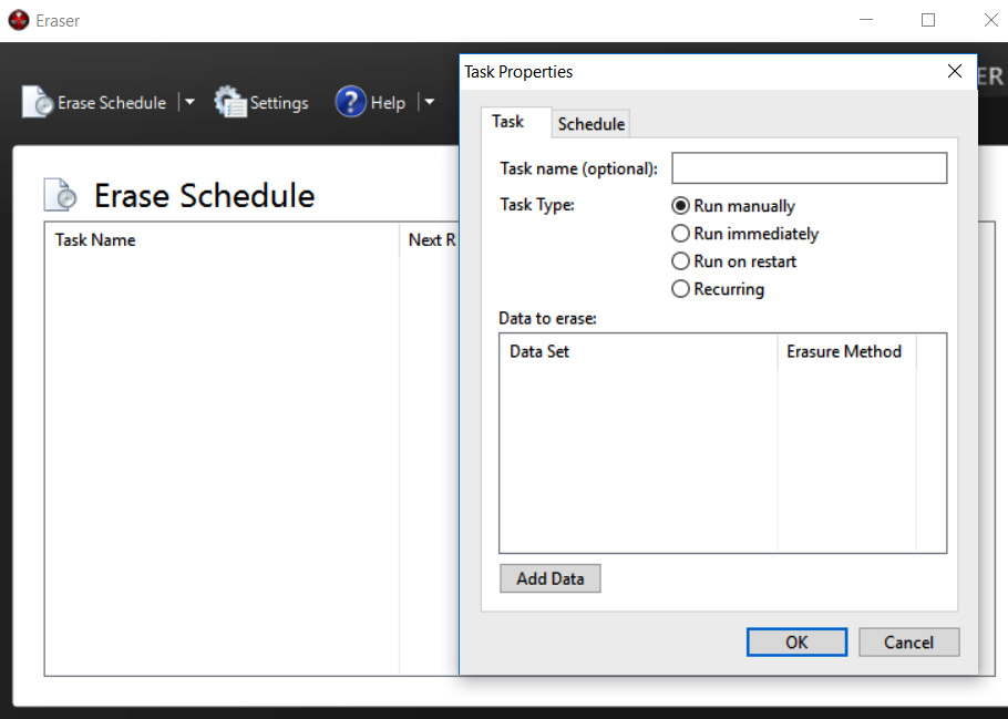
Figure 8.4 – Setting Eraser task
- Now, a task name can be assigned. This is helpful when you wish to properly document the erasure of the evidence drive. Click the Add Data button. This will open another window:
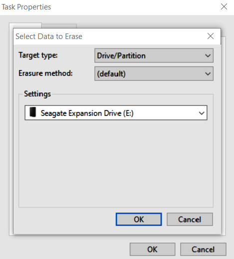
Figure 8.5 – Eraser drive selection
- For Target type, select Drive/Partition. In the Settings area, there will be a drop-down list of partitions and drive letters. Pay very close attention to the drive letters that are assigned to the various drives and ensure that the external drive that requires wiping is selected. In this case, a new Seagate external HDD is being utilized. Finally, select an erasure method. There are several different options for wiping drives. In this case, the US DoD 5220.22-M (8-306./E) (3 Pass) wiping option is selected:
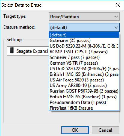
Figure 8.6 – Erasure method selection
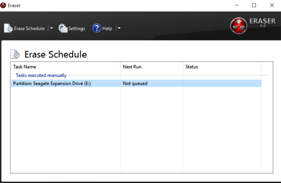
Figure 8.7 – Erase Schedule
- Right-click the Partition: Seagate Expansion Drive (E:) task and click Run Now. This will start the wiping process. As we mentioned previously, ensure that the correct evidence drive is being wiped.
Depending on the size of the drive and the system that is performing the wipe, this process can take hours or even days. Once it's complete, the incident response analyst should capture any information that verifies that the evidence drive has been properly wiped. This is important information to include in a written forensic analysis report as it demonstrates that the incident response analyst took appropriate measures to ensure that all evidence files were free from corruption or commingling with other files on the evidence drive.
It is recommended that incident response analysts have several drives available and that these drives be pre-wiped before any incident. This will allow incident response analysts to immediately utilize a wiped drive instead of having to wipe a drive on-site, which wastes time that would be better spent on incident-related activities.
A second preparation step that can be undertaken is to encrypt the evidence drive. Software such as VeraCrypt or another disk encryption platform can be utilized to encrypt the partition of the evidence drive that contains the evidence files. Incident response analysts dealing with confidential information such as credit cards or medical records should encrypt the evidence drive, regardless of whether it leaves the facility or not.
Two methods can be leveraged to encrypt the evidence drive. The first is to utilize encryption software on the forensic workstation that is utilized in the imaging process. This approach is limited to imaging on drives that have been removed from the system and imaged on dedicated systems that have the encryption software installed. A second option is to include encryption software on the evidence drive. In the previous section, an evidence drive was divided into two partitions. One partition was set aside for evidence files, while the second partition was utilized for tools such as those used for dumping memory files or imaging. In this scenario, the encryption software can be loaded in the tools partition, and the drive can be encrypted during the evidence imaging process. This limits the number of changes that are made to the system under investigation.
Once a drive is prepared, another layer of protection is needed to ensure that no changes are made to the suspect system during the imaging process. To ensure that no changes are made, responders should be familiar with and know how to use write blockers.
Using write blockers
Write blockers are critical components and ensure that evidence is not tainted during the imaging process. In this section, responders will be exposed to physical and software write blockers.
A key tenet of digital forensics is to ensure that no changes are made to digital evidence while processing and examining it. Any change, no matter how slight, has the potential to bring the entire examination into question. There is a distinct possibility that the evidence may even be excluded from legal proceedings if the responder is unable to articulate how they ensured that the evidence was not tainted during the examination. As a result, it is important to understand how write blockers maintain the integrity of digital evidence.
Write blockers come in two different types. The first of these is a software write blocker. This software sits between the operating system and the evidence. These are often part of any digital forensics tools that are used during the examination phase. They ensure that there is read-only access to the evidence file and that, during the examination, no changes have been made to the evidence. For example, the FTK Imager tool, which will be explored extensively in this chapter, ensures that the acquisition of digital evidence is done without any writes to the disk.
Another type of write blocker is a physical or hardware write blocker. As its name indicates, this is a physical piece of hardware that sits between the evidence drive and the system performing the acquisition. Data is allowed to pass from the evidence disk to the analysis system but not the other way around. The use of this device allows responders to clearly demonstrate that no evidence was altered during the acquisition phase.
Which type of write blocker is used is largely dependent on the type of acquisition that is being conducted. Ideally, responders should choose tools and techniques that clearly demonstrate that they took every reasonable precaution to ensure that the evidence has not been altered. Doing so significantly decreases the risk that the evidence will be excluded from any legal proceedings, and also affords the responder the ability to rely on the evidence while making a root cause determination.
With a properly staged drive and write blocker in place, responders are now able to move on and image evidence drives.
Imaging techniques
This section is the main part of this chapter in which we will focus on techniques that are available to responders who are called upon to image an evidence drive.
Once a proper repository has been configured for the image file, the incident response analyst is ready to acquire the necessary evidence. Responders will encounter suspect systems that are either powered on or have been shut down. Based on the state that responders find the suspect system in, they will have to utilize one of the following techniques. In any incident, no matter which technique is utilized, incident responders should be prepared to properly document their actions for any subsequent forensic report.
Dead imaging
Dead imaging is conducted on media that is not powered on and, in the case of hard drives, removed from the potentially compromised system. In terms of evidence preparation, this method is the most comprehensive as it allows the complete preservation and analysis of a physical volume. There are several methods and tools available, both commercial and freeware, that allow proper imaging. In addition to software, incident response analysts will often make use of a hardware write blocker. These devices ensure that no changes are made to the suspect media. As we discussed in Chapter 1, it is critical to be able to demonstrate to a court of law that no changes were made to the original evidence.
One advantage of imaging a hard drive or other digital media in this manner is that the process can be predefined and repeatable. Having a predefined process that is formalized as part of incident response planning and the procedure itself ensures that evidence is handled in a forensically sound manner.
One tool that is extremely useful in dead imaging is FTK Imager. This tool, provided by Access Data, is a forensically sound platform for acquiring a disk image.
Imaging using FTK Imager
The following process uses a hard drive and FTK Imager to produce a forensically sound image for analysis. Rushing or deviating from these steps may create a situation where the responder may not be able to rely on the evidence’s integrity, thereby making potential evidence unreliable:
- The first step is to physically inspect the evidence. Two primary focal points should be inspected. The first is the chain of custody form. Any time that you are taking custody of evidence, you should have access to the form, ensure that all steps are properly documented, and complete the entry with your information.
- Then, you need to inspect the evidence packaging to ensure that no seals have been breached. One quick way to document this is to take a photo of the evidence in the original packaging:
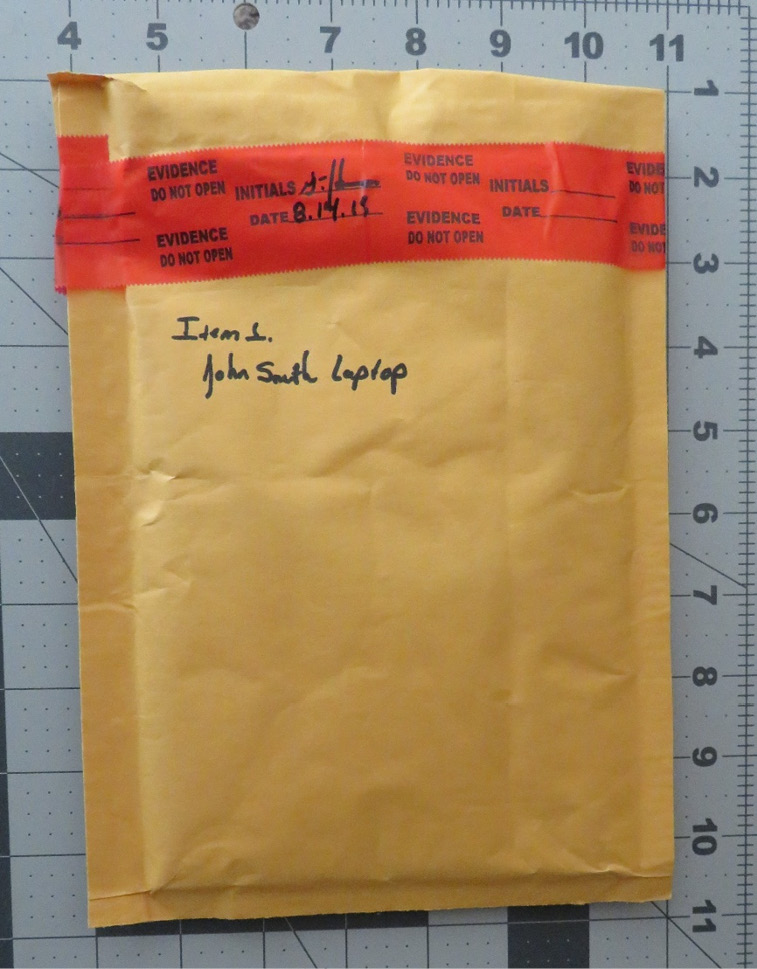
Figure 8.8 – Packaging integrity check
- In the preceding photo, we have captured all the information concerning the piece of evidence and demonstrated that, prior to imaging, the integrity of the evidence has been maintained. After the seal has been broken, you need to take another photo of the contents of the packaging:
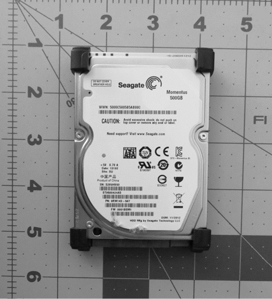
Figure 8.9 – Example disk photo
- Once a photo of the piece of evidence has been taken, you should ensure that it matches the chain of custody form. Errors can occur in an incident, and this is one way to ensure that mistakes in the chain of custody are corrected as early as possible. By confirming the chain of custody, any mix-ups can be rectified. The next step is to configure the physical write blocker. In this case, a Tableau TK35u USB 3.0 Forensic IDE/SATA Bridge Kit is utilized as a physical write blocker. The suspect drive is attached via the included SATA drive adapter and a FireWire connection is made to the imaging laptop. When utilizing a physical write blocker, ensure that the device indicates proper functioning, as demonstrated here:
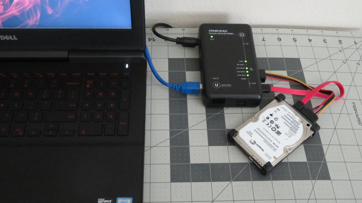
Figure 8.10 – Physical write blocker setup
With the physical write blocker in place, the suspect drive is now ready for imaging. In this example, the FTK Imager freeware application will be used. FTK Imager requires administrator privileges to run. Open the executable; the following screen will appear:
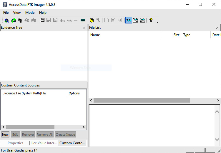
Figure 8.11 – FTK Imager main menu
- Click on File and then Create Disk Image. This will open a window where you can select the media source. In this case, select Physical Drive so that the entire drive, including the MBR, will be captured for further analysis. Then, click Next:
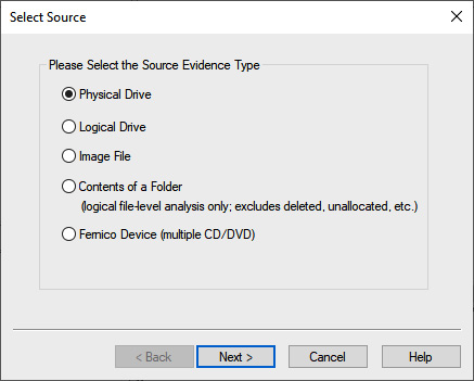
Figure 8.12 – FTK Imager source selection
- The next window allows the analyst to select which drive will be imaged. Incident response analysts should pay close attention to ensure that they are imaging the correct device since all devices that are visible to the operating system are listed. Here, you need to pay attention to the storage space of the drives to differentiate between the suspect and image drives. In this case, four separate drives are listed. Two are drives contained within the imaging laptop. Another drive is the destination drive. In this case, the third drive, labeled \.PHYSICALDRIVE2, is the correct suspect drive. Highlight this drive and click Finish:
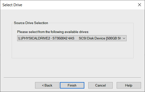
Figure 8.13 – Suspect drive selection
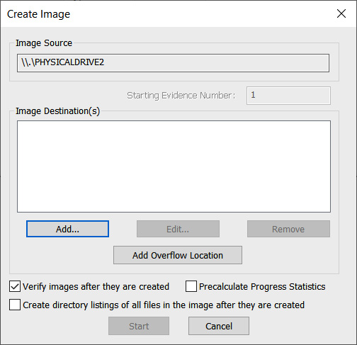
Figure 8.14 – FTK Imager Create Image window
- At this point, choose the type of image file you want to create. Four options are available. In this case, E01 needs to be selected. Click Next >:
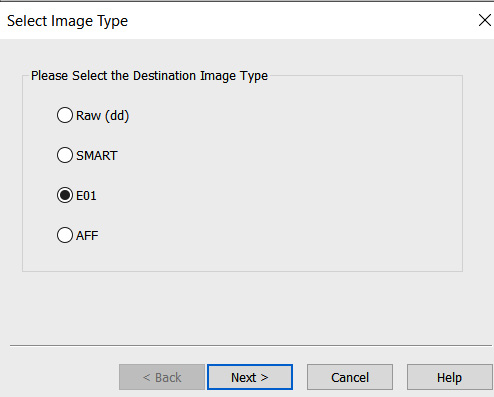
Figure 8.15 – FTK Imager Select Image Type window
- In the next window, enter information specific to the image. We will discuss reporting in Chapter 13. For now, the analyst should complete the fields with as much detail as possible since this information will be included in the forensic report. Once the fields have been filled in, click Next >:
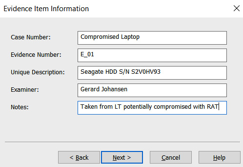
Figure 8.16 – FTK Imager Evidence Item Information window
- In the next window, verify that the image destination and filenames are correct. In addition to this, you’ll be able to set the image fragmentation size and compression. The fragmentation size can be set to 0 since this is where the entire disk image will be contained within a single file. For now, the defaults will be utilized since mounting a disk image that is fragmented is not an issue. Once the information you’ve entered has been verified as correct, click Finish:
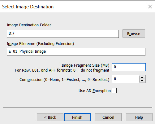
Figure 8.17 – FTK Imager Select Image Destination window
- Now, the Create Image window will open. This is the final stage and is where the analyst can cancel the creation of the image file. There are also two options that the analyst should enable, depending on the use case. The first of these involves FTK Imager verifying the image after it’s been created. In this feature, FTK Imager will verify that no changes have been made and that the image file is complete and without errors. Second, FTK Imager can create a list of all files on the image. This may be handy for the analyst in the event that a specific file(s) has evidentiary value. The analyst will be able to determine whether the file is on this system. This can save time if several drives have to be examined. Once all the settings have been verified, click Start:
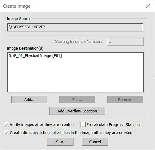
Figure 8.18 – FTK Imager Create Image window
- FTK Imager will then begin the process of imaging the drive. This can take several hours or even days, depending on the size of the drive being imaged, the available processing speed of the imaging system, and the type of connection (FireWire, USB, and so on) to the imaging system. While this is happening, the following window will appear:
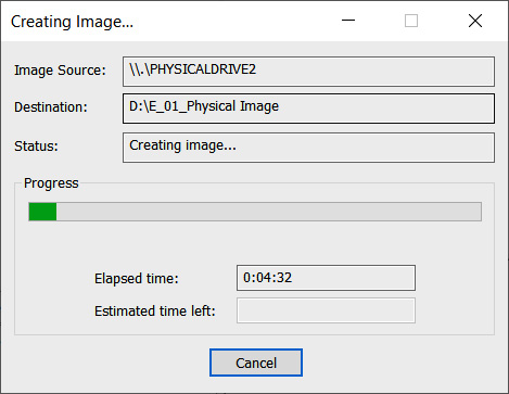
Figure 8.19 – FTK Imager Creating Image window
- Once FTK Imager has completed the imaging process, a window will open. In this window, FTK Imager will provide the incident response analyst with detailed information. Something that should be of concern to analysts is the hashes that have been computed for both the drive and the image. In this case, both the MD5 and Secure Hash Algorithm 1 (SHA1) hashes match, indicating that the imaging process captured the drive properly and that no changes have been made to the evidence that was taken from the suspect drive. It’s good practice to include this information as part of the forensic report:
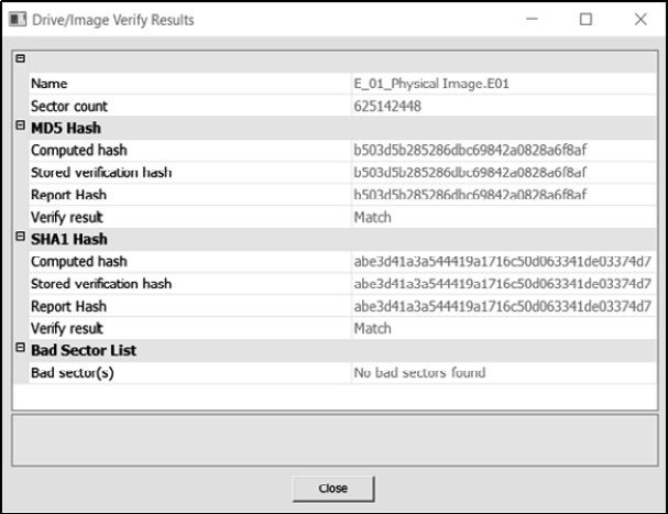
Figure 8.20 – FTK Imager result verification
- Navigate to the evidence drive. Here, the entire image can be located. Depending on how FTK has been configured regarding fragment size, there may be several files or a single evidence file. In addition to the evidence files, FTK Imager provides a full list of all files on the hard drive.
- Finally, FTK Imager provides a text file with detailed information concerning the imaging process. This information should be captured and included with any subsequent forensic reporting. At this point, the imaging process has been completed and the evidence drive needs to be returned to secure storage.
Dead imaging provides the most forensically sound acquisition; however, there may be times when responders will have to image a system that is powered on. This would necessitate the responder to perform live imaging of a suspect system.
Live imaging
In live imaging, the system is running, and the analyst uses a USB storage drive to house the imaging program and the storage area. One simple technique is to simply copy the FTK Imager directory installed on an imaging workstation to a USB and execute it from there on the target system. Before that, though, the analyst should perform a few checks on the system.
Exterro FTK Imager guidance
FTK Imager can easily be configured to run from a USB device. It is recommended that analysts have at least one or two of these handy. For detailed information on how to configure a USB device, consult the Exterro website: https://exterro.freshdesk.com/support/solutions/articles/69000765662-run-ftk-imager-from-a-flash-drive-imager-lite.
Pre-imaging checks
Introduced over a decade ago, Microsoft BitLocker is the native FDE solution used on Windows OS systems. In addition to BitLocker, there are a host of FDE products. These solutions make it difficult for incident response analysts to conduct an analysis of a system. A handy tool to determine if a system is using BitLocker is Magnet Forensics’ Encrypted Disk Detector tool, available at https://www.magnetforensics.com/resources/encrypted-disk-detector/.
Simply download the tool and run it via the command line. For example, the following screenshot shows that the target system is running BitLocker:
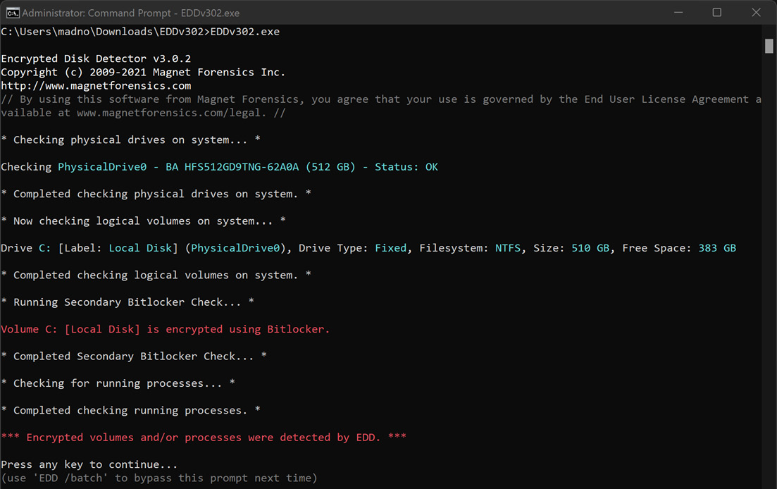
Figure 8.21 – Encrypted Disk Detector
An additional check that should be performed is determining if the system has an HDD or SSD and if TRIM is enabled. Refer to the previous section on SSDs for the specific command that can be run.
Virtual systems
Responders will often encounter virtual servers and even workstations as part of an investigation. Virtualized systems can be acquired by simply exporting a paused virtual machine (VM) to a removable drive. In other instances, responders can make use of the snapshot feature of a virtual system. This creates a separate file that can be analyzed at the date and time a snapshot is taken. In either case, responders should make sure that the drive has been sanitized properly and that the proper documentation has been addressed.
To acquire a VM, simply pause the system and then move the entire directory to the external media. (In some instances, this can even be accomplished remotely.) In Windows virtual platforms such as VMware, several files make up the virtual image:
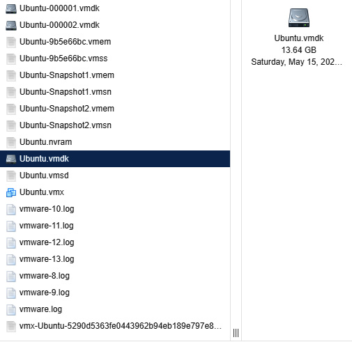
Figure 8.22 – ESXi VM files
Let us look at some of the files:
- .vmdk: This is the virtual disk image file. This is the logical volume where the virtual operating system and files reside. Obtaining these files is much like imaging the C: drive on a physical system.
- .vmem: The .vmem file is the virtual memory file. This is the storage area for the virtual RAM or physical memory. This file can be exported and combined with an additional file for analysis using the methods that will be discussed in Chapter 10.
- .vmss: The VMware suspended state file saves the running configuration of a suspended VM. This includes process and network connection data. This file is combined with the .vmem file to provide the system memory.
- .vmsn: This is the virtual snapshot state file. This file contains the state of the system when the snapshots were taken.
Incident responders can use these files in several ways. First, the .vmdk file can be mounted the same way as an image file can in various digital forensics software platforms. These will be discussed in Chapter 9. Second, the .vmsn file can be used to reconstruct the system by simply copying the file and working with the facsimile. From here, responders can look at the behavior of the system or extract evidence without impacting the original .vmsn file.
Finally, the running memory that is captured through the .vmem and .vmss files can be analyzed in much the same way you would analyze other memory captures. To obtain the proper forensic data, the two files must be combined. This can be done by utilizing the vmss2core.exe tool, which is included as part of the VMware suite of tools. To combine these files, the following command syntax needs to be used:
C:VirtualToolsvmss2core.exe -W "InfectedServer.vmss" "InfectedServer.vmem"
The preceding command will produce a memory dump in the directory containing the two files.
Although virtualization is common in large enterprises, it should not represent a significant challenge. In some ways, the ability to simply pause a system and extract all the necessary files makes extracting the necessary evidence faster.
Thus far, the focus has been on Windows tools for imaging. Another option available to incident responders is the use of Linux imaging tools. There are a variety of tools that provide write-blocking and imaging capabilities that are often open source.
Linux imaging
Chapter 3 provided an overview of various forensic tools that are available to the incident response analyst. Some of these tools include Linux distributions that can be leveraged during an incident for various digital forensics tasks. The following example will demonstrate how a Linux distribution with forensics applications can be deployed to capture a forensically sound image of a potentially compromised computer.
The combination of a Linux distribution and a bootable USB device is an option you can use to conduct forensic imaging of potentially compromised systems. Incident response analysts may find themselves in a situation where multiple systems need to be imaged and the analysts have only one write blocker. A great deal of time will be wasted if the analyst must image each one of these systems in sequence. In this situation, the analyst can avoid this by creating a bootable USB drive for each system and imaging each one at the same time. All that the analyst needs are an evidence drive and a bootable USB drive for each source of evidence. Utilizing this technique will allow the analyst to image each system at the same time, saving time that is better spent on other activities.
In this scenario, the Computer Aided INvestigative Environment Live (CAINE) Linux distribution will be utilized to image the hard drive from a potentially compromised system. First, the system is powered off and the bootable USB device containing the CAINE OS is installed. The suspect system is then powered on. Incident response analysts should be aware of how to change the boot order of a system to ensure that it boots to the USB device. Analysts should also be prepared to immediately power down the system if it attempts to boot into the native OS and not the USB device. Let’s get started:
- Ensure that the system with the suspect drive is powered off. Insert the forensic OS drive into one of the available USB ports. Now, power on the computer and access the BIOS. This is usually a combination of the function (fn) key and the F2, F8, or F12 key. If the system starts the host operating system shut down the system and try again. It is a good practice to find out how to access the BIOS for the system before starting the process.
- Once you boot into the forensic OS, insert the evidence drive into another available USB port. Open the terminal and type the following command:
caine@caine:~$sudo fdisk -l
The fdisk -l command lists all partitions that are visible to the CAINE OS. The output will look like this:
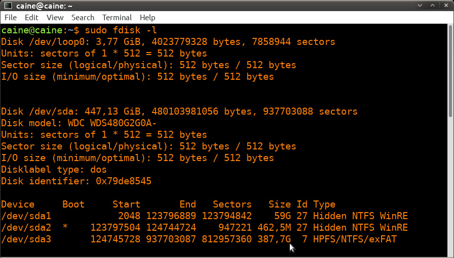
Figure 8.23 – fdisk output data
In the preceding screenshot, the first disk indicated is SDA, with 447.13 GB of storage. Further down, the SDA disk is divided into three separate partitions. The partition labeled SDA2 is the boot partition. With the SDA3 partition, it has a size of 387.7 GB, as shown by the cursor arrow. This is the data storage area where the bulk of the digital evidence will be located. It is the SDA disk that will be imaged.
Scrolling down through the output, the evidence and CAINE OS drive are also visible:
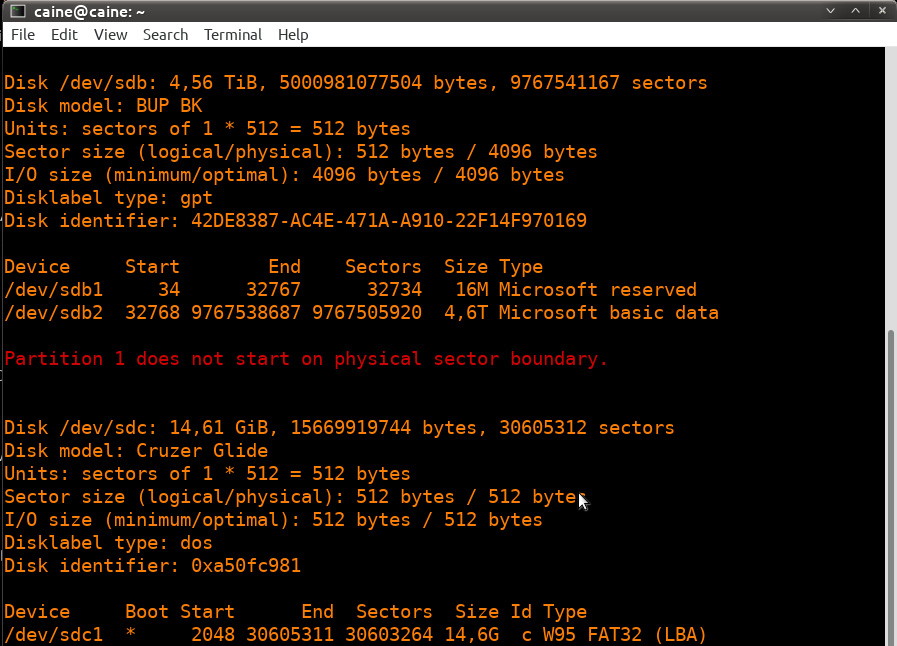
Figure 8.24 – fdisk output data
In the preceding screenshots, there are three separate disks, each with its own partitions. The disk labeled /dev/sdc is the USB drive that contains the CAINE OS that the system has been booted from. The /dev/sdb disk is the evidence drive that the system will be imaged to. Finally, the target system is labeled as /dev/sda.
- After identifying the proper target drive of the system, we want to confirm that the imaging process will not change the data. The CAINE OS has a built-in software write blocker. On the desktop, you will find Block on/off, which is the title of the actual path to the software write blockers. This opens the software write blocker that will be utilized. While examining the list of devices, you will see that the only one that is writable is SDB, which we previously identified as the evidence drive. The other drives are set to read-only. This assures the incident response analysts that the imaging process will not alter the target drive (it is a good idea for analysts to take a screenshot of such information for subsequent reporting):
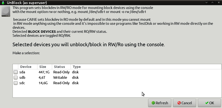
Figure 8.25 – UnBlock device selection
- After verifying that the evidence drive is in place and that the target system has been set to read-only, configure the evidence drive so that it is mounted properly. Create a directory called Disk_Images or a similar name as a repository for this and any subsequent disk images using the following command:
caine@caine:~$ sudo mkdir /mnt/Disk_Images
- Next, mount the SDB disk on the mount directory that was created in the last step with the following command. Make note that in this case, it is the larger disk partition of the evidence drive:
caine@caine:~$sudo mount /dev/sdb2 /mnt/Disk_Images
Now, the evidence drive has been mounted on the mount point that was created.
- Next, change the directory to the evidence drive by using the following command:
caine@caine:~$ cd /mnt/Disk_Images
- Make a directory for the system’s specific image file. In this case, the directory will contain the incident number Incident2022-034, as the directory. It is a good idea to make this directory tie indirectly with the incident in some fashion. The following command will create the proper directory:
caine@caine:~$ mkdir Incident2022-034
- Change to the directory created in step 7 by executing the following command:
caine@caine :/ mnt /Disk_Images$ cd Incident2022-034
- Now that you’re in the proper directory, all you need to do is image the suspect drive. There are several tools available for doing this. In this example, the Dc3dd tool will be used. This tool was developed by the Department of Defense Cyber Crime Center (DC3) forensic specialist Jesse Kornblum. This application has additional features that aren’t found in the dd Linux imaging application. These include error reporting and multiple hashing algorithms that can be leveraged on the fly. To start the imaging process, enter the following command:
caine@caine:/mnt/Disk_Images/Incident2022-034$ dc3dd if=dev/sda of=ACMELaptop056.img hash=md5 log=ACMELaptop56.txt
The preceding command contains dc3dd. Start by imaging the disk at sda to the evidence drive and output the image file with the name ACMELaptop056.
The command also has Dc3dd hash the image file with the MD5 algorithm. Finally, an ACMELaptop56.txt log file is created that can be utilized for reporting purposes. Running the command produces the following output:
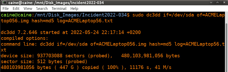
Figure 8.26 – dc3dd command and output
- Depending on the size of the drive, this process can take hours. During this time, the analyst can keep track of any progress that is made. Upon completion, the application will produce some output indicating how many sectors were utilized for input and how many sectors were used as an output to the image file. Ideally, these should be the same. Finally, an MD5 hash of the image file is calculated and utilized as a part of the output:
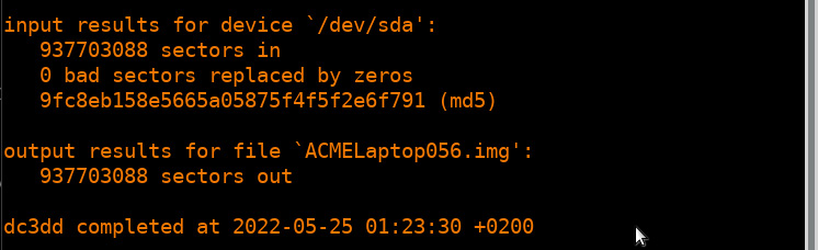
Figure 8.27 – Dc3dd imaging completion
- Examining the evidence drive from a Windows system reveals the image and log file that were created with Dc3dd:
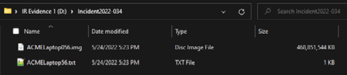
Figure 8.28 – Dc3dd output files
- Examining the log file reveals the following information, all of which should be incorporated into any subsequent reporting:
dc3dd 7.2.646 started at 2022-05-24 22:17:14 +0200
compiled options:
command line: dc3dd if=/dev/sda of=ACMELaptop056.img hash=md5 log=ACMELaptop56.txt
device size: 937703088 sectors (probed), 480,103,981,056 bytes
sector size: 512 bytes (probed)
480103981056 bytes ( 447 G ) copied ( 100% ), 11176,1 s, 41 M/s
input results for device `/dev/sda':
937703088 sectors in
0 bad sectors replaced by zeros
9fc8eb158e5665a05875f4f5f2e6f791 (md5)
output results for file `ACMELaptop056.img':
937703088 sectors out
dc3dd completed at 2022-05-25 01:23:30 +0200
Linux is a viable option when it comes to acquiring disk evidence. One significant advantage it has is that it is easy to scale. In the event that multiple systems have to be acquired, responders can use several USB storage drives and Linux USB devices and acquire them in parallel, rather than waiting for software to become available. CAINE is an excellent option for this as the included write blocker also affords a measure of evidence integrity in the process.
Imaging is a critical process for responders to understand. The incident will often dictate which technique should be used. In any incident, though, responders should ensure that the process is conducted in a sound manner as the subsequent investigation will often rely on data acquired from these systems.
Summary
Not every incident will dictate the need to obtain an image from a potentially compromised hard drive or another volume. Regardless, incident response analysts should be familiar with, and able to perform, this function when called upon. The evidence that’s found on a hard drive may be critical to determining a sequence of events or to obtaining actual files that can aid in determining the root cause of an incident. This is the central reason why responders need to understand the fundamentals of imaging and the tools and processes involved, how to create a stage drive, how to use write blockers, and how to execute any of the imaging techniques we mentioned in this chapter. As with any process that’s performed in a forensic discipline, imaging should be conducted in a systematic manner in which all the steps are followed and properly documented. This will ensure that any evidence that’s obtained will be sound and admissible in a courtroom.
In the next chapter, we will discuss examining network-based evidence in relation to the network activity that is associated with an incident.
Questions
- What are the two types of write blockers? (Select two)
- Hardware
- Digital
- Software
- Court-approved
- Responders should ensure that any storage drive that’s used for imaging is properly sanitized before each use.
- True
- False
- What type of imaging is used to acquire the entire physical volume of a drive?
- Dead imaging
- Live imaging
- Remote imaging
- Hardware imaging
- Which imaging application is found only on Linux systems?
- FTK Imager
- EnCase Imager
- AFF4
- dd
Further reading
Refer to the following resources for more information about the topics covered in this chapter:
- FTK Imager Guide: https://d1kpmuwb7gvu1i.cloudfront.net/Imager/4_7_1/FTKImager_UserGuide.pdf
- NIST Computer Forensic Tools & Techniques Catalog: https://toolcatalog.nist.gov/search/index.php?ff_id=1
- An Overview of Disk Imaging Tool in Computer Forensics: https://www.sans.org/reading-room/whitepapers/incident/overview-disk-imaging-tool-computer-forensics-643