There is no substitute for the comfort supplied by the utterly taken-for-granted relationship. | ||
| --Iris Murdoch | ||
Topics Covered in This Chapter
Types of Relationships
Identifying Existing Relationships
Establishing Each Relationship
Establishing Relationship Characteristics
Relationship-Level Integrity
CASE STUDY
Summary
As you learned in Chapter 3, a relationship is a connection between a pair of tables. A relationship exists when the tables are connected by a Primary key and a Foreign key, or are linked together by a linking table; the manner in which the tables are connected depends on the type of relationship that exists between them.
A relationship is a crucial part of the database because
it establishes a connection between a pair of tables that are logically related to each other in some form or manner. The logical relationship exists between the data contained in the tables. For example, a logical relationship exists between the data in a Customers table and the data in an Orders table. Because a customer places an order for a specific piece of merchandise, a record in the Customers table (representing the customer) is related to a record in the Orders table (representing a particular order).
it helps to further refine table structures and minimize redundant data. These benefits come about as a result of the manner in which the tables are connected. The process used to establish the relationship modifies the table structures in a manner that makes them more efficient.
it is the mechanism that allows data from multiple tables to be drawn together simultaneously. In Chapter 12 you'll learn that fields from related tables can be combined into a View, which allows you to view (and, in some cases, modify) the data as if it were in a single table.
Relationship-level integrity is established when a relationship is properly defined. Establishing relationship-level integrity guarantees that the relationships are reliable and sound. And, as you know, relationship-level integrity is a component of overall data integrity.
In order to take advantage of the many benefits provided by a relational database, you must make certain that you establish each relationship carefully and properly. Failure to do so can make working with multiple tables at the same time difficult, and it can also make inserting, updating, and deleting records in related tables difficult. These types of problems are discussed later as the design process unfolds.
Before you begin to establish relationships between tables in the database, you must learn what types of relationships can exist between a pair of tables. Two tables that are related to each other have a specific type of relationship. Knowing how to properly identify each type of relationship is invaluable for designing a successful database.
As you learned in Chapter 3, there are three possible types of relationships that can exist between a pair of tables: one-to-one, one-to-many, and many-to-many.
Note
A "generic" example of each type of relationship follows. It's a good idea to learn how to visualize a relationship generically first—that way you can learn to identify more clearly the type of relationship that exists between a pair of tables. It also causes you to be more objective when you are determining a relationship between a pair of tables.
Each discussion also includes an example of how the relationship is diagrammed. Any special instructions pertaining to the diagramming process are included in the discussion. Symbols used in the diagrams will be explained as necessary. This method of presentation allows you to see how the symbols are used in the context of the diagram and keeps you from having to memorize them all at once.
The first symbols you will use to diagram table relationships are shown in Figure 10-1.
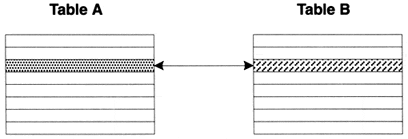
A pair of tables are defined as bearing a one-to-one relationship if a single record in the first table is related to one and only one record in the second table, and a single record in the second table is related to one and only one record in the first table. Figure 10-2 shows a generic example of a one-to-one relationship.
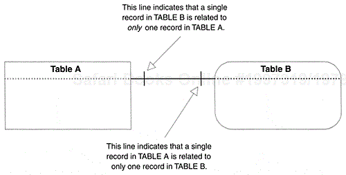
In Figure 10-2, a single record in Table A is related to only one record in Table B, and a single record in Table B is related to only one record in Table A. A one-to-one relationship usually (but not always) involves a subset table. For the sake of example, assume that Table B is the subset table. Figure 10-3 shows how to diagram a one-to-one relationship.
In a relationship diagram, the type of relationship is indicated by the type of line drawn between the tables. Later in this chapter, you'll learn how to indicate the characteristics of the relationship on the diagram as well.
A one-to-many relationship is defined as one in which a single record in the first table can be related to one or more records in the second table, but a single record in the second table can be related to only one record in the first table. Two diagrams are needed to illustrate this type of relationship.
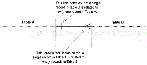
Say you're working with two tables, TABLE A and TABLE B. A one-to-many relationship exists between these tables because a single record in TABLE A can be related to one or more (but not necessarily all) records in TABLE B, and a single record in the Table B can be related to only one record in TABLE A.
This is the most common relationship found between a pair of tables, and it is the easiest to identify. Figure 10-6 shows how to diagram a one-to-many relationship.
A many-to-many relationship exists between a pair of tables if a single record in the first table can be related to one or more records in the second table, and a single record in the second table can be related to one or more records in the first table.
Assume once again that you're working with Table A and Table B. A many-to-many relationship exists between these tables because a single record in Table A can be related to one or more records (but not necessarily all) in Table B, and a single record in Table B can be related to one or more (but not necessarily all) records in Table A.
Figure 10-9 shows how to diagram a many-to-many relationship.
Before you can use the data from the tables involved in a many-to-many relationship you must resolve a few problems. If the relationship is not properly established,
one of the tables involved in the relationship will contain a large amount of redundant data. . You would have to introduce duplicate fields into one of the tables (which, as you know, results in producing redundant data) to establish this relationship, unless you know the proper procedure.
both tables will contain some amount of duplicate data because of the redundancies. . If you introduce duplicate fields into one of the tables, you get duplicate data in both tables.
it will be difficult to insert, update, and delete data in the participating tables. . When you introduce duplicate fields, the same data (in the duplicate fields) has to be maintained in both tables, rather than in one table.
In order to illustrate these problems, consider the table structures in Figure 10-10. There is a many-to-many relationship between the Students table and the Classes table—one student can attend many classes, and one class can be associated with many students.
Currently there is no actual connection between the two tables. Unless you know how to properly establish a many-to-many relationship, you would probably be inclined to add the Class ID, Class Name, and Instructor ID fields from the Classes table to the Students table in order to identify the classes in which a student is currently enrolled. But you will see the problems that arise from such modifications if you "load" the revised Students table with sample data. Figure 10-11 shows the "amalgamated" version of this table loaded with sample data.
The problems with an improperly established many-to-many relationship are well-illustrated in Figure 10-11:
There are unnecessary duplicate fields. . It is very likely that the Class Name and Instructor ID fields are not appropriate in the Students table—the Class ID field identifies the class sufficiently, and it can be used effectively to identify the classes a student is taking.
There is a large amount of redundant data. . Even if the Class Name and Instructor ID fields are removed from the Students table, the presence of the Class ID field still produces a lot of redundant data.
It is difficult to insert a new record. . If someone tries to enter a record in the Students table for a new class (instead of entering it in the Classes table) without also entering student data, the fields pertaining to the student would be Null—including the Primary key of the Students table. As you know, this would automatically violate the Elements of a Primary key; a Primary key cannot be Null.
It is difficult to modify the value of a duplicate field. . It would be difficult to modify a value in the Class Name field for two reasons: you have to be sure to make the modification in both tables, and you have to scan the values of the Class Name field carefully in order to make certain that you make the modification to all the appropriate values. It's very common for values in a field such as this to be entered in several ways, thus making any modification to the values more difficult. For example, note the difficulty you would have if it were necessary to modify the name of the "Advanced Music Theory" class or the "Introduction to Political Science" class.
It is difficult to delete a record. . This is especially true if the only data about a new class has been recorded in the particular student record you want to delete. Note the record for Gregory Piercy, for example. If Greg decides not to attend any classes this year and you delete his record, you will lose the data for the "Intro. to Database Design" class. That might not create a serious problem—unless someone neglected to enter the data about this class into the Classes table as well. Once you deleted Greg's record, that would mean you'd have to reenter all of the data for the class in the Classes table.
Fortunately, you will not have to worry about these problems: you're going to learn the proper way to establish a many-to-many relationship.
Reminder
Before you begin to work through the examples in the remainder of the chapter, now is a good time to remember a principle I presented in the introduction: "Focus on the concept or technique and its intended results, not on the example used to illustrate it." There are, without a doubt, any number of ways that the tables in these examples (and in the case study as well) can be related, depending on each table's role within a given database. The manner in which the examples are used here is not important; what is important is that you learn the proper techniques to identify and establish relationships between tables. Once you learn the techniques, you can identify and establish relationships for any pair of tables within any context you may encounter.
Establishing relationships always involves a three-step procedure: identifying the relationships that currently exist between the tables in the database, establishing each relationship in the appropriate manner, and then setting the proper characteristics for each relationship. When the relationships are in place, the tables are ready to be incorporated into Views. You'll learn how to define and use a View later, in Chapter 12.
When you were composing the table descriptions earlier in the database design process (back in Chapter 7, to be exact), you assembled a representative group of users and management to help you with that task. These people were also designated to represent the organization to help with decision making for the remainder of the database design process. At this stage you'll arrange for further meetings with this group to help you identify table relationships.
These people can provide valuable input because they can be expected to have a good perspective of how various subjects (or tables) are related. Although their perceptions of the manner in which these -subjects are related may not always be complete or accurate, their contributions will still be useful in identifying most of the relationships. Relationships that are harder to identify can usually be clarified by "loading" given tables with some sample data; the sample data commonly reveals the type of relationship two tables should have.
In the first step of the procedure, you'll identify the relationships that currently exist between the tables. Begin this step by taking a particular table—you can choose a table at random because you'll repeat this process for every table anyway—and determine whether it has a relationship with any of the remaining tables. For example, assume you're working with these tables:
| BUILDINGS | ROOMS |
| CLASSES | STAFF |
| FACULTY | STUDENTS |
Say you've decided to start with the CLASSES table. Make up a two-column list, writing "Classes" in the first column and writing the names of the remaining tables in the second column, as shown in Figure 10-12.
Now determine whether the CLASSES table bears a relationship with any of the other tables in the list by using the process of elimination. You're only looking for direct relationships; There must be a specific connection between tables participating in a direct relationship. Tables that are indirectly related will be implicitly connected through a third table. (You don't have to worry about indirect relationships yet.)
Eliminate a pair of tables on the list by asking the participants questions about the records in each table. You want to determine the relationship between a single record in one table to one or more records in the other table, and vice versa. (Remember that each record represents a single instance of the subject represented by the table.) There are two types of questions you can ask:
Associative. . General in nature, this type of question can be generically stated as follows: "Can a single record in (name of first table) be associated with one or more records in (name of second table)?" For the example in Figure 10-12, you might use an associative question such as
"Can a single record in Classes be associated with one or more records in Buildings?"
Contextual. . This type of question contrasts a single instance of the subject represented by the first table against multiple instances of the subject represented by the second table. There are two categories within this type of question: ownership oriented and action oriented.
Ownership-oriented questions are characterized by the use of words or phrases such as "owns," "has," "is part of," and "contains." (An example of this type of question is "Can a single order contain one or more products?") Action-oriented questions use action verbs such as "make," "visit," "place," "teach," and "attend." (An example of this type of question is "Does a single flight instructor teach one or more types of classes?")
Use the type of question you believe to be the most appropriate for the pair of tables you're working with. After you've chosen the type of question you want to use, pose the question twice—once from the perspective of the first table, and then again from the perspective of the second table. The answers to both of these questions will identify the type of relationship that exists between the tables.
Continuing with the example, assume that this is your first question:
"Is a single class held in one or more buildings?"
The answer to this question will reveal the type of relationship that exists between these tables from the perspective of the Classes table. If the answer is
"A single class is held in only one building."
then a one-to-one relationship exists between these tables. If the answer is
"A single class may be held in more than one building."
then there exists a one-to-many relationship between the two tables.
Assume you are told that a single class is held in only one building. You now follow up with this question:
"Is a single building used to conduct one or more classes?"
The answer to this question reveals the type of relationship from the perspective of the Buildings table. If the answer is yes, then a one-to-many relationship exists between these tables; if no, it's a one-to-one relationship.
Often relationships will differ from one perspective to the other. When both a one-to-one and a one-to-many relationship are identified for a particular pair of tables, the one-to-many becomes the "official" relationship for these tables, because it accurately represents the relationship from both perspectives.
Now diagram the relationship as shown in Figure 10-13 and cross out this pair of tables on the list.
Although you began asking about relationships from the perspective of the Classes table, the relationship you discovered is diagrammed from the perspective of the Buildings table. Always diagram one-to-many relationships from left to right—your diagrams will be consistent, and they'll be easier to read in the long run. Also note that each table's Primary key has been added to the diagram. From now on, make certain that each time you diagram a table you include its Primary key. (As you'll see in the following step, the Primary key is useful when you are establishing relationships.)
Continue this procedure of identifying relationships for each pair of tables on the list. Keep in mind that some pairs of tables will have a direct relationship; others will not. You want to identify only direct relationships. After you've crossed out each pair of tables on the list, select another table, create a new list, and repeat this process. When you've finished identifying all the appropriate relationships, move on to the next step.
This step involves defining a connection between the tables for each relationship. The manner in which you define the connection is determined by the type of relationship that exists between the tables.
One-to-one and one-to-many relationships are established by using a Primary key and a Foreign key to connect the tables within the relationship. You'll learn the definition of a Foreign key in just a moment.
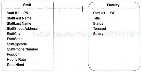
In this type of relationship, one of the tables is referred to as the "main" table and assumes a dominant role in the relationship; the other table is referred to as the "subordinate" table and assumes a -subordinate role in the relationship. In some instances, you can arbitrarily decide what role each table is to play within the relationship. In the case where one of the tables is a subset table, the subset table is usually assigned the subordinate role. But there are instances in which a subset table can assume the dominant role within the relationship. As you can see, this type of one-to-one relationship exists between the Staff and Faculty tables shown in Figure 10-14.
You establish a one-to-one relationship by taking a copy of the Primary key from the main table and inserting it into the subordinate table, where it becomes a Foreign key. The name "Foreign key" comes from the fact that the subordinate table has its own Primary key, and since the field being added is the Primary key of a different table, it is "foreign" to the subordinate table. As long as you can visualize this process generically, you'll be able to establish a one-to-one relationship properly for any pair of tables involved in this type of relationship.
As you can see in Figure 10-14, the Primary key of the main table (Staff) already exists in the subordinate table (Faculty). That is because Faculty is already a properly defined subset table. (You learned how to define a subset table properly in Chapter 7, and you established its Primary key in Chapter 8.)
Next consider the one-to-one relationship between the two tables shown in Figure 10-15.
In this example, Managers is a subset table of Employees, but it has a direct relationship to Departments. A single manager is associated with only one department, and a single department is associated with only one manager; Managers is the main table, and Departments is the subordinate table. (This is a good example of an instance in which a subset table is in the dominant position within a relationship.) To establish the relationship between these tables, take a copy of the Primary key from the main table (Mangers) and insert it into the subordinate table (Departments). Then identify the new Foreign key (Employee ID) by placing the letters "FK" next to its name. The result of these steps is shown in Figure 10-16.
Note that the relationship diagram now shows both the Primary key and the Foreign key, and that each end of the connecting line points specifically to them, making it easier to identify the relationship and the fields used to establish the connection.
The technique used to establish a one-to-many relationship is similar to the one used to establish a one-to-one relationship. In this case, you take a copy of the Primary key from the table on the "one" side of the relationship and insert it into the table on the "many" side, where that field becomes a Foreign key. For example, consider the one-to-many relationship between the Buildings table and the Rooms table shown in Figure 10-17.
In this example, a single building can contain one or more rooms, but a single room is contained within only one building. You establish this relationship by taking a copy of the Primary key from the table on the "One" side (Buildings) and inserting it into the table on the "Many" side (Rooms), where it becomes a Foreign key. Now diagram the relationship, making the proper adjustments as you did with the diagram for the one-to-one relationship. Your diagram should look like the one shown in Figure 10-18.
When you diagram a one-to-many relationship, make certain that the connection point on the "One" side points to the Primary key, and that the connection point on the "Many" side points to the Foreign key. (Note that the middle line of the "crow's-foot" is the significant connection point—it should point directly to the Foreign key.) Setting up your diagram this way makes it easier to identify the relationship and the fields used to establish the connection.
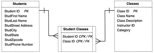
A many-to-many relationship is established using a linking table. You create the linking table by taking a copy of the Primary key from each table involved in the relationship and using those Primary keys to create the new linking table. Next you give the linking table a meaningful name, one that represents the nature of the relationship between the two tables. Then add the linking table to the final table list and make the proper entries for "Table Type" and "Table Description." Figure 10-19 shows a diagram of a many-to-many relationship that has been established for the Students and Classes tables. (Note the new diagram symbol used to represent a linking table.)
There are several points to note about the results of creating this linking table:
The many-to-many relationship has been dissolved. . There is no longer a direct relationship between the Students and Classes tables. It has been replaced by two direct one-to-many relationships: one between Students and Student Classes and another between Classes and Student Classes. In the first relationship, a single record in Students can be associated with one or more records in Student Classes, but a single record in Student Classes table can be associated with only one record in Students. In the second relationship, a single record in the Classes table can be associated with one or more records in Student Classes table, but a single record in Student Classes can be associated with only one record in Classes.
The Student Classes linking table is assigned a Composite Primary key, composed of two fields: . Student ID and Class ID. Except in rare instances, a linking table always contains a Composite Primary key.
The Student Classes linking table contains two Foreign keys. . Each of the two fields in the linking table is a copy of a Primary key from another table. Therefore, each is a Foreign key by definition and is treated as such individually. It is only when the fields are treated as a unit that they are referred to as the Composite Primary key of the table.
The linking table helps to keep redundant data to an absolute minimum. . There is no superfluous data in this table at all. In fact, the main advantage of this table structure is that it allows you to enter as few or as many classes for a single student as is necessary. Later in the database design process, you'll learn how to create Views to draw the data from these tables together in order to present it as meaningful information.
The name of the linking table reflects the purpose of the relationship it helps establish. . The data stored in the Student Classes table represents a student and the classes in which he or she is enrolled.
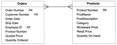
As you work with many-to-many relationships, there will be instances in which you will need to add fields to the linking table in order to reduce data redundancy and further refine the table structures. For example, consider the many-to-many relationship between the Orders and Products tables shown in Figure 10-20.
As you can see, this relationship is improperly established—the fields Product Number, Quoted Price, and Quantity Ordered were inserted into the Orders table in order to associate various products with a particular order. But the presence of these fields in the Orders table produces a large amount of redundant data, as shown in Figure 10-21.
There is so much redundant data largely because only one Product Number can be entered into each record. Therefore, if a customer orders eight items, eight records will have to be entered in this table for this one order—one record for every item the customer orders. You can completely avoid this problem by properly establishing the relationship between the Orders and products tables with a linking table. Figure 10-22 shows a diagram of this relationship as it should be established.

Figure 10-21. The problematic Orders table, which results from an improperly established many-to-many relationship.

Figure 10-22. A properly established many-to-many relationship between the Orders and Products tables.
Although this arrangement eliminates the redundant data, there is still one minor problem: Quoted Price and Quantity Ordered are no longer appropriate in the Orders table. First and foremost, their values are not directly determined by the Primary key of the Orders table. Second, they bear no relationship to any of the remaining fields in the table. They do, however, relate to a particular Product Number that appears within a given order. Therefore, the Quoted Price and Quantity Ordered fields should be removed from the ORDERS table and placed in the ORDER DETAILS linking table. Figure 10-23 shows the revised diagram of this relationship.
Whenever you establish many-to-many relationships between tables, check each table within the relationship to determine whether there are any fields that should be transferred to the linking table. When in doubt, load all the tables with sample data; you should be able to see immediately which fields should be transferred to the linking table.
With all these techniques in mind, establish each of the relationships you identified in the previous step. Make certain you create a diagram for each relationship—you'll add new information to each diagram as the design process further unfolds.
Once you've established the relationships between tables, review all of the table structures. As you established each relationship, you made modifications to the existing table structures and created several new table structures. (Remember the linking tables?) Therefore, you want to make certain that each table conforms to the Elements of the Ideal Table:
It represents a single subject, which can be an object or event.
It has a Primary key.
It does not contain multipart fields.
It does not contain multivalued fields.
It does not contain calculated fields.
It does not contain unnecessary duplicate fields.
It contains only an absolute minimum amount of redundant data.
If you determine that a table is not in conformance with the Elements of the Ideal Table, identify the problem and make the necessary modifications. Then take the table through the appropriate stages of the database design process until you reach the stage we're at now. As long as you've been following proper procedures thus far, you shouldn't encounter any problems with the tables.
As you've seen, a Primary key from one particular table becomes a Foreign key in another table when that field is used to establish a relationship between those two tables. A Foreign key must conform to a set of elements, just as all the other keys you've worked with so far.
It has the same name as the Primary key from which it was copied. . This rule should be adhered to unless there is an absolutely compelling reason not to do so. (Such a reason is shown in the example under "Alias" in Chapter 9.)
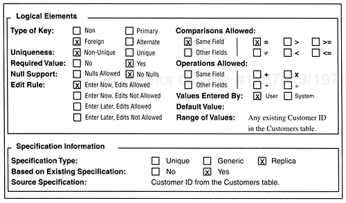
It uses a replica of the Field Specifications for the Primary key from which it was copied. . This is in accordance with the sixth element of the Elements of the Ideal Field, as you learned in Chapter 7. There are, however, a few settings in the Logical Elements category of the Field Specifications that will be slightly different for the Foreign key than for its parent Primary key. Figure 10-24 shows the Logical Elements for an Employee ID field used as a Primary key in the Employees table, and Figure 10-25 shows the Logical Elements for the same Employee ID field when it is used as a Foreign key in the Orders table.

Figure 10-24. The Logical Elements category for the Employee Id field when it is being used as a Primary key in the Employees table.
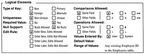
Figure 10-25. The Logical Elements category for the Employee Id field when it is being used as a Foreign key in the Orders table.
As you can see in Figure 10-25, three minor changes have been made to these elements. The Type of Key setting is indicated as "Foreign" because the Employee ID field is being used as a Foreign key in this instance. The Uniqueness setting is designated as "Non-Unique" because you want to be able to associate a single employee with many orders; if you marked this as "Unique," you'd only be able to enter an employee into the Orders table one time, which would greatly limit his or her sales potential! The Edit Rule setting is designated as "Enter Now, Edits Allowed" because there will be times when the wrong employee is credited for an order and you'll need to be able to change the value to reflect the correct employee for the order.
The setting in the Specification Information category of the field specification is also different for a Foreign key as compared with that of the Primary key from which it was created. Figure 10-26 shows the Specification Information for the Employee ID field used as a Foreign key in the Orders table.

Figure 10-26. Specification Information for the Employee Id field when it is being used as a Foreign key in the Orders table.
A Foreign key uses a replica field specification because its specification is based on an existing Primary key's unique specification. Make certain you include the name of the Primary key's parent table in the Source Specification item, as shown in Figure 10-26. This makes it easy to compare the -Primary key's specifications and the Foreign key's specifications as the need arises.
It draws its values from the Primary key to which it refers. . A Foreign key's range of values is limited to existing values of the Primary key to which it refers. For example, you cannot enter an invalid Employee ID into the Orders table. Any Employee ID you enter into the Orders table must first exist as an Employee ID in the Employees table. This ensures consistency in the values of both fields in both tables.
Review the Foreign keys in each table to make certain that they conform to the Elements of a Foreign key. If they are not in accordance with these elements, make the appropriate modifications. But if you've followed proper procedure up to this point, it should be a rare instance when you would have to make any changes.
The final step in this procedure is to establish the characteristics of each relationship. These characteristics indicate what will occur when a record is deleted, the type of participation each table bears within the relationship, and to what degree each table participates in the relationship.
Now you must establish a deletion rule for the relationship. This rule defines what will happen if a user places a request to delete a record in the main table of a one-to-one relationship or in the "one" side of a one-to-many relationship. Defining a deletion rule for a relationship helps to guard against "orphaned" records, which are records that exist in a subordinate table of a one-to-one relationship but have no related records in a main table, or records that exist in the "many" side of a one-to-many relationship that have no related records in the "one" side.
Two options are available for the deletion rule:
Restrict. . The requested record cannot be deleted if there are related records in the subordinate table of a one-to-one relationship or the "many" side of a one-to-many relationship. Related records must be deleted before the requested record can be deleted.
Cascade. . The requested record will be deleted as well as all related records in the subordinate table of a one-to-one relationship or the "many" side of a one-to-many relationship.
Use a restrict deletion rule as a matter of course; use a cascade deletion rule very judiciously. The best way to determine whether a cascade deletion rule is appropriate for a set of related tables is to study the relationship diagram for those tables. Consider the diagram shown in Figure 10-27.
Select a pair of related tables and pose the following question:
"If a record in [name of main or `one' table] is deleted, should related records in [name of subordinate or `many' table] be deleted as well?"
Here the question is framed so that you can understand the premise behind it. When you pose this question against a particular pair of tables, such as the Customers and Orders tables, just "fill in the blanks." The question now becomes:
"If a record in the Customers table is deleted, should related records in the Orders table be deleted as well?"
If the answer to this question is no, you must use a restrict deletion rule for this relationship; otherwise, the cascade deletion rule is appropriate. The answer to this question greatly depends on how the data is being used within the database. If you cannot easily provide an answer, make note of the relationship and continue with the next table relationship. You'll revisit these relationships when you establish Business Rules for the database later in Chapter 11.
After you've identified the type of deletion rule you want to use for a relationship, add it to the relationship diagram. Restrict deletion rules are indicated by an "(R)" and cascade deletion rules by a "(C)." Place the designation under the connection line of the main table or the table on the "one" side of the relationship as shown in Figure 10-28.
You probably noticed that the deletion rule only applies to a record in the main table or the "one" side of the relationship. There is no need to worry about deleting records in the subordinate table or the "many" side of the relationship because there can be no adverse affects as a result of doing so.
Each table participates within a relationship in a particular manner. A table's type of participation determines whether a record must exist in that table before a record can be entered into the other table. There are two types of participation:
Mandatory. . There must be at least one record in this table before you can enter any records into the other table.
Optional. . There is no requirement for any records to exist in this table before you can enter any records into the other table.
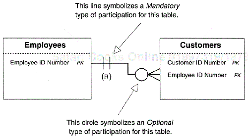
The type of participation for most tables is usually determined later when you're defining Business Rules. However, it's common to establish the type of participation for tables in relationships where the type of participation for each table is obvious, is a result of common sense, or is in accordance with some particular set of standards. Consider the one-to-many relationship between the Employees and Customers tables shown in Figure 10-29.
Say that in this instance, a particular employee must be assigned to each customer. This employee acts as the customer's "account representative" and takes care of all transactions and communications between the organization and that customer. Although each customer must be associated with a particular employee, not every employee is required to be associated with even a single customer. Remember that many of the people represented in the Employees table perform some other function within the organization and may never come into contact with a customer at all.
This scenario does not describe or define any special circumstances; it is the way the organization conducts its business. Therefore, you can infer that
the type of participation for the Employees table should be designated as "Mandatory." . The Employees table must have at least one record because each customer is required to be associated with a particular employee.
the type of participation for the Customers table should be designated as "Optional." . It is unnecessary for any records to exist in the Customers table before you can enter an employee into the Employees table.
Once you've determined the type of participation for each table within the relationship, modify the relationship diagram to reflect this new information. A mandatory type of participation is symbolized by a vertical line; an optional type of relationship is symbolized by a circle. Figure 10-30 shows the relationship diagram for the Employees and Customers tables and illustrates the use of these two symbols.
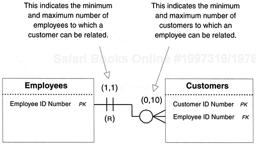
Now you must determine the degree to which each table will participate within the relationship. This is a simple matter of identifying the total number of records in one table that can be related to a single record in the other table. The factors used in determining the degree of participation—obvious circumstances, common sense, or conformance to some set of standards—are the same as those used to determine the type of participation. Therefore you will identify the degree of participation for some tables now and leave the remaining tables to be revisited when you define Business Rules for the database.
The degree of participation is symbolized by two numbers, separated by a comma, and enclosed in parentheses, such as "(1,8)." The numbers in this symbol represent the lower and upper boundaries, respectively, of the total number of records in one table that can be related to a single record in the other table. In this instance, a single record in one table can be related to a minimum of one record and a maximum of eight records in the other table.
When you add this symbol to a relationship diagram, place it over the connection line of the appropriate table. Figure 10-31 illustrates the proper use of this symbol within a relationship diagram. This particular diagram indicates the degree of participation for the relationship between the Employees and Customers tables.
In this example, the diagram indicates that a customer must be related to at least one employee, but no more than one. It also indicates that an employee is not required to be associated with a customer. On the other hand, an employee cannot be associated with more than ten customers.
Figure 10-32 shows an example of an unlimited degree of participation, which is represented by the letter N inside the parenthesis. In this instance, a customer can exist within the Customers table without being associated with an order in the Orders table. On the other hand, a particular customer can be associated with an unlimited number of records in the Orders table. You certainly wouldn't want to limit the amount of purchases a customer can place.
Now that you know how to define the characteristics of a relationship, execute this step for every relationship you've established thus far. As you identify these characteristics, revise the diagram for each relationship to reflect the new information.
The very last order of business is to verify the relationships. This is a relatively easy task that can be performed using the following checklist:
Make sure that each relationship between a pair of tables has been properly identified.
Make certain that each relationship has been properly established.
Make certain that each Foreign key is in conformance to the Elements of a Foreign key.
Make sure that the proper deletion rule has been established for each relationship.
Make certain that the proper type of participation has been identified for each table within the relationship.
Make certain that the appropriate degree of participation has been established for each table within the relationship.
If all the relationships check out and everyone agrees to this assessment, you can be confident that the relationships are sound and are ready to be used to create Views.
Relationship-level integrity is a direct result of properly establishing a table relationship and defining its characteristics in the proper manner. In establishing relationship-level integrity, you have
made certain that the connection between two tables in a relationship is sound. . You have accomplished this by using a Primary key and a Foreign key to establish a one-to-one and one-to-many relationship, and a linking table to establish a many-to-many relationship.
ensured your ability to insert new records into each table in a meaningful manner. . You have made this possible by properly identifying the type of participation for each table within the relationship.
ensured your ability to delete an existing record without creating adverse affects. . This is guaranteed by the deletion rule defined for the relationship.
established a meaningful limit to the number of records that can be interrelated within the relationship. . You have made this possible by properly identifying the degree of participation for each table within the relationship.
As you know, relationship-level integrity is the third component of overall data integrity. (The first is table-level integrity and the second is field-level integrity.) In the next chapter, you'll establish the final component of overall data integrity by learning how to establish Business Rules for the database.
It's now time to identify the relationships that exist for the tables that appear on the final table list for Mike's Bikes. Your assistant, Zachary, is working on this part of the design process. The tables Zachary is working with are
| Customers | Products |
| Employees | Vendors |
| Invoices |
The first order of business is to identify the relationships that currently exist between the tables. Because there are few tables in this database, Zachary elects to meet with only Mike; Zachary figures that Mike should be familiar enough with the tables to help him identify the relationships.
Zachary and Mike have easily determined that the following tables bear a one-to-many relationship:
Customers and Invoices. . A single customer can be associated with one or more invoices, but a single invoice is associated with only one customer.
Employees and Invoices. . A single employee can be associated with one or more invoices, but a single invoice is associated with only one employee.
They've also determined that these two tables have a many-to-many relationship:
Invoices and Products. . A single invoice can be associated with one or more products, and a single product can be associated with one or more invoices.
Zachary diagrams the relationships and then sets them aside for the moment. He's not quite sure about a particular relationship, so he discusses it with Mike.
| Zachary: | I wanted to ask you about the relationship between the Products and Vendors tables. Can a single product be associated with one or more vendors? |
| Mike: | Yes, in a manner of speaking. What I mean is, a single type of product—such as a bike lock—can be associated with one or more vendors. However, each lock is given its own product number and treated as a distinct item, regardless of the vendor who supplies it. Now, if the true meaning of your question is `Can a single record in the Products table be associated with one or more records in the Vendors table?' then the answer is no because each record in the Products table contains a reference to only one vendor in the Vendors table. |
| Zachary: | I thought as much. In that case, there's a one-to-many relationship between the Vendors and Products tables. I automatically figured that a single vendor could be associated with many products in the Products table. |
Zachary now diagrams the one-to-many relationship between the Vendors and Products tables and continues with the next step. He establishes the one-to-many relationships by taking a copy of the Primary key from the "one" side of the relationship and inserting it into the "many" side as a Foreign key, and then he revises the relationship diagrams accordingly. One of the diagrams is shown in Figure 10-33.
Zachary then establishes the many-to-many relationship between the Invoices and Products tables by creating a new linking table called Invoice Products, with the Composite Primary key made up of the Invoice Number and Product Number keys. The relationship diagram for these tables is shown in Figure 10-34.
Now Zachary reviews each table structure to ensure that it conforms to the Elements of the Ideal Table; fortunately, all the table structures are sound. Next he refines the Foreign keys in each table by making certain that each one conforms to the Elements of a Foreign key. He then modifies the Logical Elements and Specification Information categories of each Foreign key's Field Specifications sheet as warranted. The modifications he has made for one of the Foreign keys is shown in Figure 10-35.
Next Zachary establishes the appropriate relationship characteristics for each table in a relationship. He defines a deletion rule for each relationship and then identifies both the type of participation and the degree of participation for each table within the relationship. Zachary finishes this step by adding this new information to the relationship diagram. One of the finished diagrams is shown in Figure 10-36.
Finally, Zachary reviews and verifies all of the table relationships with Mike. He checks each relationship against his final checklist and marks it as "Completed."
We opened this chapter with a discussion of the three types of relationships that can exist between a particular pair of tables—one-to-one, one-to-many, and many-to-many. You now know that the one-to-many is the most common relationship that occurs between a pair of tables, and that the many-to-many relationship gives rise to problems that must be resolved.
Next we discussed how to identify the relationships that exist between tables in a database. We looked at the types of questions that can be used to help accomplish this task: associative and contextual.
The chapter continued with a discussion of how relationships are established. You learned that one-to-one and one-to-many relationships are established by using Primary keys and Foreign keys, and that many-to-many relationships are established using linking tables. You also learned that you must review all of the table structures to ensure that they still conform to the Elements of the Ideal Table. Foreign keys must be refined as well, and you must make certain that they are in accordance with the Elements of a Foreign key.
We then discussed relationship characteristics. You now know how to define a deletion rule for the relationship, and that the two settings for a deletion rule are Restrict and Cascade. Next you learned how to identify the type of participation and degree of participation for each table within a relationship. As you now know, a table's type of participation can be set at either Mandatory or Optional. You also know that the degree of participation gauges the total number of records in one table that can be associated with a single record in the other table. Finally, you learned that you must verify the relationships with users and management, and that you can use a checklist to accomplish this task.
The chapter closed with a look at relationship-level integrity. You learned that this type of integrity is established by properly defining a relationship and its characteristics. Once relationships are properly established, they are ready to be used in Views.


