

Creating Particle Simulations
Particle simulations are a mainstay of visual effects work and are generated within 3D and compositing programs. Particle simulations are able to recreate a wide range of fluid, semi-fluid, vaporous, combustive, and shattered-surface substances and events. For example, particle simulations are used to create water, mud, sparks, fire, smoke, dust, explosions, and debris (Figure 6.1).
This chapter includes the following critical information:
• Review of built-in particle plug-ins
• Creating dust puffs, sparks, smoke, and water with particle effects
• Review of third-party plug-ins and an introduction to Trapcode Particular

FIG 6.1 Raindrops, puddles, and ripples are added to a shot using particle and blur effects, as well as masking and 3D layers.
Whether particles are simulated in After Effects or a 3D program such as Autodesk Maya, the basic workflow is generally the same. The steps include:
1. An emitter is created and positioned. The emitter generates n number of particles per second. The emitter may be an omnidirectional point, have a geometric volume, or may take the form of a plane or piece of geometry.
2. The particles, at their moment of birth, are given various attributes, such as size (measured as a radius), initial velocity, initial direction, and so on.
3. Optionally, forces are added to simulate the physical world and alter the particle movement. Most often, gravity is applied, but other forces (also called fields) may be added to simulate natural events such as turbulence or wind. If no forces are applied, the simulation acts as if the particles are in a vacuum.
4. Optionally, particles are made to “die” off within a certain number of seconds, frames, or randomly within a time range. Some particle systems allow for particle collisions with boundaries or with geometry. The collisions may cause particle death or the spawning of additional sub-particles.
5. Particles are rendered with a chosen shading quality and lighting. Particles can emulate a wide range of materials, including vaporous smoke, cohesive liquids, embers, and so on.
3D programs such as Autodesk Maya, Autodesk 3ds Max, and Side Effects Houdini can create incredibly complex particle simulations. Therefore, particle simulations are often delivered to visual effects compositors as completed renders. Nevertheless, the renders often need additional adjustment to make them usable. In fact, the renders may appear crude or incomplete until effects are applied within After Effects or similar programs. For example, particle renders may require additional blur effects or color grading.
Using Built-In Particle Effects
After Effects includes several particle simulation effects. These include Particle Playground, CC Particle World, and CC Particle Systems II. (CC stands for the software developer, Cycore Effects.) Although the effects are not as advanced as some third-party particle plug-ins, they are often suitable for simple phenomena, such as dust puffs, smoke, and sparks. The following sections and tutorials demonstrate the use of these plug-ins.
Additional Cycore Effects plug-ins are designed for specific simulations that require a particle-like motion. These include CC Drizzle, CC Bubbles, CC Snowfall, and CC Rainfall. You can find these in the Effect > Simulation menu. CC Drizzle and CC Rainfall are demonstrated as part of the tutorial at the end of this chapter.
Creating Dust Puffs with Particle Playground
A common visual effect element is a dust puff. Such puffs are often used to indicate an object’s connection with the ground, wall, or some other surface. The object may be a piece of falling debris or the foot of a character. If the character comes in the form of green screen footage or a 3D render, the puffs help strengthen the connection of the character to the ground. You can also add dust puffs to live-action footage to accentuate the footsteps. For example, an included example uses the Particle Playground effect to add dust to a close-up of an actor’s feet. The main steps needed to create the puffs follow:
1. A solid layer the same size as the composition is placed on top of the layer outline. The layer color is not important as the particle effect eventually replaces the solid. The live-action shot is placed at the bottom of the layer outline.
2. The Particle Playground effect is added to the solid. (Choose Effect > Simulation > Particle Playground.)
3. The effect’s emitter is placed below a foot at the point that the foot touches the ground. With this example, the right foot steps down on frame 19. The emitter location is set by the Position property in the Cannon section. The Cannon section also holds properties for critical qualities like size, velocity, direction, and particle numbers (Figure 6.2).
4. The particles are scaled up with the Particle Radius property so they overlap. To make a short puff, the Particles Per Second property is animated off to on to off over a short period of time. For example, the property is keyed to change from 0 to 5000 to 0 over a period of 6 frames.
5. The Barrel Radius property is increased to create the particles over the width of the foot. The Velocity value is increased to create greater particle speed. The Direction Random Spread and Velocity Random Spread are increased to create greater variety in the particle motion.
6. By default, the particles drift upwards, which works for a footstep. You can change the particle direction by altering the Direction property. You can also strengthen gravity by raising the Force value in the Gravity section. By default, the built-in gravity pulls the particles downwards.

7. The particle color is changed to brown through the Color property (in the Cannon section). By default, the particles are square and live forever. Hence, additional effects and adjustments are needed to make the particles more dust-like.
8. To remove the squarish nature of the particles, a blur effect is added. For example, a Fast Blur with Bluriness set to 100 blends and softens the particle mass (Figure 6.3).
9. The solid layer’s Opacity is keyed to change from 0 percent to 10 percent. The particles are “killed off” by setting a later keyframe back to 0 percent. With a low Opacity value, the particles appear like a thin, undulating dust. You can alter the Opacity animation to create thinner or thicker dust (Figure 6.4).
In general, dust puff effects can remain subtle. As long as the particle color matches the ground material or general scene lighting and the particles take on believable motion (i.e., puffing, drifting, or wafting), a simple particle simulation is all that is necessary. You can add complexity to the simulation by adding multiple iterations of the particle effect and giving each iteration a unique emitter location and property values. An example project file is saved as particle_playground.aep in the ProjectFilesaeFilesChapter6 directory.

FIG 6.3 The particles are made brown and blurred with the Fast Blur effect. The live action is temporarily hidden.

FIG 6.4 Left to right: Particles layered over the live-action footage with 0 percent, 30 percent, and 10 percent Opacity.
Creating Sparks with CC Particle Systems II
Sparks are another visual effect element that is commonly used. Sparks may be added to explosions, electrical short circuits, collisions between metal and other surfaces, or futuristic gun blasts. The following steps detail the creation of generic sparks with the CC Particle Systems II effect.
1. A new solid layer is created and placed on top of the layer outline. The layer color is not important as the particle effect eventually replaces the solid.
2. The CC Particle Systems II effect is added to the solid. (Choose Effect > Simulation > CC Particle Systems II.)
3. The default simulation creates a burst of particles, which fall downwards. You can see this by playing back the timeline. To reduce the number of particles, the Birth Rate property is reduced (Figure 6.5). You can also turn the particle emitter off by keyframing the value at 0. With this example, the Birth Rate is animated, changing from 0 to 1.0 to 0 over a span of 4 frames. Birth Rate is kept below 1.0 to create a small number of particles.

FIG 6.5 Adjusted Particle Systems II properties.
4. You can time the particle burst so that it corresponds to a particular event in the live-action footage by animating the Birth Rate property. As an alternative, you can create the particle simulation in its own composition and nest the result within a different composition that carries the live-action footage. This allows you to “slide” the nested particles back and forth on the timeline to line the particle birth with a particular event.
5. You can place the emitter in a different position by altering the Position X and Y values in the Producer section. With this example, the emitter is left in its default position. To enlarge the area in which the particles are born, the Radius X and Y values are increased.
6. By default, the particle burst is omnidirectional. However, the particles quickly fall due to gravity. You can alter the basic forces through the Physics section. For this example, the Gravity property is reduced to 0.5.
7. By default, any particle that is born lives forever. To force them to “die” within 12 frames (half a second at 24 fps), Longevity (Sec) is set to 0.5.
8. Particle Systems II supports different particle types. To create a more three-dimensional look to the sparks, the Particle Type menu, in the Particle section, is set to Shaded Sphere. To reduce the particle size, Birth Size is set to 0.05 and Death Size to 0.07. With these settings, the particles shrink over their lifetime. If you change the particle type, you may need to adjust the Birth Rate values.
9. By default, the particle Birth Color is yellow and Death Color is red. This is suitable for sparks, although you are free to change the color swatches.
10. To make the particles more spark-like, a Glow effect is added (Effect > Stylize > Glow). Glow Threshold is set to 0 percent, Glow Radius is set to 15, and Glow Intensity is set to 3. The Glow Colors menu is changed to A & B Colors; Color A is set to orange, and Color B is set to dark red. This produces a glowy halo around each spark (Figure 6.6).
11. You can add motion blur to particle simulations in After Effects. Hence, motion blur is activated for the solid layer and the entire composition.

FIG 6.6 The final spark simulation. The Glow effect and motion blur add realism to the particles.
When the solid layer is placed over a live-action footage layer, you can set the solid layer’s blending mode menu to Screen. The Screen mode ensures that only the bright areas of particles appear over lower layers. An example project file is saved as particle_systems.aep in the ProjectFilesaeFilesChapter6 directory.
Creating Smoke with CC Particle World
You can create smoke with particle effects in After Effects. So long as the smoke does not require a rounded, three-dimensional quality, a simple particle simulation will suffice. (If a more volumetric smoke is required, a simulation created in a 3D program or a more advanced plug-in, such as Trapcode Particular, will create a better result.) The following tutorial demonstrates the creation of simple smoke.
CC Particle World mini-tutorial
You can follow these steps to create rising smoke with CC Particle World:
1. Create a new project. Import the ProjectFilesPlatesParticlesFactory.##.png image sequence. Interpret the sequence as 30 fps by RMB-clicking the sequence name, choosing Interpret Footage > Main, and setting Assume This Frame Rate to 30.
2. LMB-drag the sequence to the timeline to create a new composition. The sequence features an aerial shot of a factory. Several of the smokestacks produce a brownish smoke. However, in the foreground, the shorter smokestack does not (see Figure 6.11 at the end of this tutorial). We’ll add smoke to this stack.
3. Create a new solid layer (Layer > New > Solid Layer). Make the solid the same size as the composition. The solid color does not matter. The solid layer is placed automatically at the top of the layer outline.
4. With the solid layer selected, choose Effect > Simulation > CC Particle World. The solid color is replaced with a spherical emitter (called a producer), a shower of particles, a reference grid, and an axis control cube at the top left.
5. To more easily see the emitter and axis cube, temporarily turn off the particles by setting the effect’s Birth Rate property to 0. While on the first frame of the timeline, LMB-drag the axis reference cube. This rotates the effect’s built-in camera view of the emitter. Roughly orient the emitter and grid so that the camera is looking down on the emitter. You can move the emitter left/right and up/down by LMB-dragging the emitter in the Composition view. Continue to adjust the axis cube and emitter position until the emitter is slightly lower than the top of the foreground smokestack (Figure 6.7)
6. Expand the Particle World sections in the Effect Controls panel. Set Birth Rate to 25 and Longevity (Sec) to 6. Note that the emitter position is stored by the Position X, Y, and Z values in the Producer section. Set Radius X, Y, and Z to 0.025. Radius determines the width of the emitter.

FIG 6.7 The particles are temporarily hidden to show the emitter (producer) sphere, reference grid, and axis cube. The axis cube is adjusted so that the effect camera looks down on the emitter and grid.
7. In the Physics section, change the Animation menu to Cone Axis. This generates a widening column of particles as opposed to the default explosive pattern. Change Velocity to 0.4 and Resistance to 5. This betters matches the speed of the particles to the smoke that exists in the image sequence. Reduce Gravity to 0.1 so the particles do not fall back to the bottom of the frame. Play back the timeline to see the simulation. Stop at a middle frame. Interactively adjust the Gravity Vector X, Y, and Z values. This points the gravity vector in a different direction to bias the direction the particles are moving. Leave Gravity Vector X, Y, and Z set to –0.2, –1.0, –0.2. Play back. This makes particles flow in a slight right-to-left and upward direction.
8. In the Particle section, change Particle Type to Faded Sphere. This converts the particle simulation into a soft-edge mass. Change Birth Size to 0.2 and Death Size to 0.6. Reduce Max Opacity to 3 percent to give the particles a semitransparent look that matches the smoke in the footage. Slight changes to Max Opacity cause significant differences in the final look of the particles. Change the Birth Color to tan and Death Color to brown. You can use the eyedropper to sample the smoke in the image sequence. To better see the particles with low Opacity, temporarily hide the image sequence layer.
9. In the Extras section, change the Depth Cue Type menu to Fade. This affects the way the particles are combined from the view of the camera. The Fade setting fades the particles based on distance so that the particle mass is less opaque (Figure 6.8).
10. Unhide the image sequence and play back. At this point, the particle smoke location does not correspond with the smokestack opening. You can animate the emitter’s Position X, Y, and Z to match the emitter location to the smokestack opening. However, this leads to sudden “bends” in the flow of smoke. As such, it’s better to motion track the footage and apply the motion tracking data to the solid layer. With the factory layer selected, choose Animation > Track Motion. In the Layer view, position Track Point 1 so it sits over a detail of the smokestack opening. Analyze to produce a motion track for the entire timeline. Click the Edit Target button in the Tracker panel and choose the solid layer. Click the Apply button in the Tracker panel. The solid layer gains position animation. To better line up the smoke with the stack, adjust the solid layer’s Anchor Point values. You can temporarily raise the Max Opacity of the particle effect to better see where the particles are born (Figure 6.9). If necessary, you can also adjust the solid layer’s Scale. For example, set Scale to 100 percent, 125 percent to stretch the particles vertically and prevent the solid layer edge from becoming visible in the frame. (For more information on motion tracking, see Chapter 4.)

FIG 6.8 The particle mass, as seen on frame 50 with the image sequence hidden.
11. Despite the addition of motion tracking, the particles may continue to overlap the top of the smokestack. To prevent this, you can add a mask that either cuts off the bottom of the particles or creates a “patch” that covers up the bottom of the particles. With this project, a patch creates a cleaner result. To create a patch, copy the image sequence layer with Edit > Duplicate and place the copy on top of the layer outline. With the Pen tool, draw a mask on the new top layer that occludes the particles that are lower than the smokestack (Figure 6.10). Return the Max Opacity of the particles back to 3 percent to see an accurate result. Animate the mask shape over time to follow the smokestack.

FIG 6.9 The solid layer, which carries the particles, is motion tracked. The red motion path is visible. The Max Opacity of the particles is temporarily set to 50 percent.
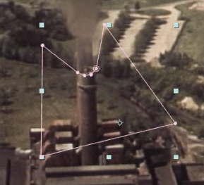
FIG 6.10 A mask is drawn to create a patch, which covers up any particles lower than the smokestack opening.
Although the particles are subtle and somewhat hard to see on a single frame, the playback reveals an undulating mass that looks like rising smoke (Figure 6.11). A finished version of this project is saved as mini_particle_world.aep in the ProjectFilesaeFilesChapter6 directory. The image sequence is taken from “The Power to Serve,” an industrial film from the Prelinger Archives, made available via a Creative Commons Public Domain license. For more information, visit www.archive.org/details/prelinger.

FIG 6.11 Top: The footage without particles. Bottom: The footage with the final particle simulation.
There are many third-party plug-in effects that create particle simulations within After Effects. Here’s a partial overview of those available at the time of this writing.
Trapcode Particular supports simulations with millions of particles and offers the ability to move a camera through the particle simulations, create long-exposure particle trails, and add natural lighting and shading that emulates a wide range of natural phenomenon. This plug-in is discussed further in “An Introduction to Trapcode Particular” later in the chapter.
Element 3D supports particle/geometry arrays, whereby you can distribute 3D geometry across a particle simulation. (Visit www.videocopilot.net.)
This plug-in provides a large set of ready-made particle emitters that simulate a wide range of natural phenomena, including water, fire, smoke, explosions, and so on. (Visit www.wondertouch.com.)
Plexus 2 integrates the particle simulations with After Effects cameras and lights and offers algorithms to build organic particle-based structures. (Visit www.rowbyte.com.)
Phenomena provides particle simulation tools to create such effects as fire, bubbles, rain, snow, electrical arcs, muzzle flashes, sparks, and so on. (Visit www.digieffects.com.)
Newton 2 supports complex, physics-based simulations with a wide range of dynamic forces and body types. As opposed to working within a 3D environment, Newton 2 converts After Effects 2D layers into dynamic bodies. (Visit motionboutique.com.)
An Introduction to Trapcode Particular
The Red Giant Trapcode Particular plug-in shares some of the basic functionality of the standard particle plug-ins that come with After Effects. The Trapcode Particular effect generates particles with emitters and dynamic simulations. You can choose different styles of particles and alter qualities such as size, velocity, and shading. However, Particular offers a much larger set of properties that you can adjust. In addition, Trapcode Particular offers sub-particle generation, where each initial particle generates additional particles based on specific events. Sub-particles are ideal for creating light streaks or smoke trails. Trapcode Particular also provides built-in motion blur and depth-of-field rendering properties.
When you install Trapcode Particular, it includes a large number of animation presets. To apply a preset, add a solid layer to your current composition, go to the first frame of the timeline, select the new solid layer, go to the Effects & Presets panel (along the right side of the program window), and double-click a preset name. For example, double-click Animation Presets > Trapcode Particular Ffx > Trapcode HD Presets > t2_explodeoutdark_hd. The Particular effect is added to the layer with its properties altered (Figure 6.12). You are free to change any of the property values or change any of the keyframe animation. In fact, starting with a preset can save a significant amount of time when setting up a complex simulation. Although many of the presets are designed for motion graphics tasks, many others are suitable for visual effects work. These include explosions, fireworks, smoke trails, flames, snow, star fields, and welding sparks (the presets carry these descriptions as part of the preset names).

FIG 6.12 Portion of Trapcode Particular properties as set by the t2_explodeoutdark_hd preset.
Like other particle effects, Trapcode Particular renders the particles to a 2D layer. However, Particular offers various means to make the particles appear three-dimensional. These are briefly discussed here.
You can move and rotate a 3D camera around the particle mass. The perspective shifts appropriately. The layer carrying the particles does not have to be a 3D layer. (For more information on 3D cameras, lights, and layers, see Chapter 5.) By default, the particles render with depth of field, as per the camera settings. By default, the particles exhibit motion blur if motion blur is activated for the composition.
You can set the Emitter Type menu, in the Emitter section, to Box or Sphere. This generates particles within a volume area. The size of the emitter is set by Emitter Size X, Y, Z. Regardless of the emitter type, you can also set the Direction property to determine the particle’s initial direction. For example, if you set Direction to the default Uniform, the emitters kick out particles in an omnidirectional fashion. If you set the Direction menu to Directional, the particles flow in the direction determined by the X, Y, Z Rotation properties. When compared to built-in particle effects, such as Particle Systems II, Trapcode creates a more convincing sense that particles are receding in depth along the Z-axis, even if no 3D camera is present in the composition.

FIG 6.13 The Cloudlet particle type with Shadowlets activated creates puffy smoke trails.
Particular provides several different particle types. Sphere, Cloudlet, and Streaklet types support edge feathering. These are ideal for creating smoke, explosions, and other soft-edged phenomena (Figure 6.13). You can set the type though the Particle Type menu, found in the Particle section. The Feather is set by the property with the Feather suffix.
By default, Particular particles are flat-shaded with a color set by the Color property in the Particle section. However, you can activate self-shadowing and create a sense of three-dimensionality by changing the Particle Type to Cloudlet or Streaklet and setting the Shadowlet For Main menu, in the Shading section, to On.
Initially, Particular particles are self-illuminated. However, you can light the particles with After Effects lights. To do so, change the Shading menu, in the Shading section, to On and create at least one light through the Layer > New > Light menu. The result is similar to lighting 3D layers. By default, the self-shadows ignore the light position. However, if you change the Placement menu to Project, the self-shadows are based on the actual light position or direction in XYZ. You can find the Placement property in the Shading > Shadowlet Settings subsection. You must add the Shadow prefix to the light layer name for the Project option to take effect.
You can force particles to shift to specific colors as they age by setting the Set Color menu to Over Life and altering the Color Over Life ramp graph (Figuer 6.14). (Note that the particle death color is at the ramp left while the particle birth color is at the ramp right.) By default, particles become less opaque over their life. However, you’re free to alter the Opacity Over Life ramp graph to make the particles more or less opaque. Particle lifespan is set by the Life [Sec] property. All of these properties are found in the Particle section.

FIG 6.14 Two simulations using different Color Over Life ramps.
If you set the Particle Type menu to a type with a Sprite or Textured suffix, you can map a layer to each particle. The layer is selected through the Layer menu, found in the Particle > Texture subsection. Sprite particles are flat, rectangular, and always face the camera. Sprites are able to read layer opacity. Textured particles are similar to sprites but are allowed to rotate.
The Aux System section is designed to create sub-particles as the primary particles move through the scene. If the Emit menu is set to Continuously, you can create steaks and trails. You can choose a sub-particle type through the Life > Type menu. The sub-particles carry their own size, color, opacity, and feather properties in this section.
For additional information on the Trapcode Particular effects, visit www.redgiant.com.
Chapter Tutorial: Creating Particle Rain
While real-world rain can be difficult to shoot in, particle rain is fairly easy to add to a shot as part of the post process. You can use almost any particle system within After Effects to create streaked raindrops. However, Cycore Effects provides two effects specifically for this task: CC Rainfall and CC Drizzle. That said, the effects may not be realistic when used as is. Hence, you can combine the effects with 3D layers, blur effects, and masking to create more complex results. To add rain to a shot, follow these steps:
1. Create a new project. Import Chair.##.png from the ProjectFilesPlatesParticlesChair directory. Make sure the frame rate is interpreted as 24 fps. LMB-drag the sequence to the timeline to create a new composition. Play back. The sequence features a short, high-angle shot of an actress. Although After Effects work has already been applied to the shot in a previous project, we can add an additional rain effect.
2. Create a new solid layer. Make the solid the same resolution as the composition. Set the solid color to black. The solid is placed automatically on top of the layer outline. With the new layer selected, choose Effect > Simulation > CC Rainfall. Vertical, gray streaks are added to the frame with each representing a raindrop blurred by a camera exposure. In the Effect Controls panel, deselect the Composite With Original check box. The rain is placed over the lower layers and the black areas are ignored. Play back. The rain is pre-animated.
3. Change the solid layer’s blending mode menu to Screen. This brightens the drops slightly. Change Drops to 500 and Size to 10 to alter the rain density and apparent closeness to camera. Change Speed to 20,000 to speed up the drop falls. Change Scene Depth to 20,000 to create a greater variety of drop widths and thus create the illusion that the drops are spread out in depth away from the camera.
4. Convert the layer into a 3D layer. Set the layer’s X Rotation to 45. This “tips” the layer towards the camera. Scale the layer to 400 percent to create the illusion that the drops are close to the camera lens (Figure 6.15). (For more information on 3D layers and the 3D environment, see Chapter 5.)

FIG 6.15 The CC Rainfall effect creates streaked raindrops in the foreground. The drops are oriented to the camera by rotating the 3D layer along the X-axis. The layer is scaled up to 400 percent.
5. To soften the drops, select the 3D layer and choose Effect > Blur & Sharpen > Directional Blur. Set the Blur Length to 50.
6. Rename the 3D layer FGRain. You can rename a layer by RMB-clicking the layer name in the layer outline and choosing Rename from the menu. Select the 3D layer and choose Edit > Duplicate. Rename the new layer MidRain. Interactively move the layer backwards along the Z-axis so it serves as a mid-ground layer of raindrops. Open MidRain’s CC Rainfall effect in the Effect Controls panel (all effects are copied when you choose Edit > Duplicate). Set Drops to 5000 and Size to 5 to make a denser field of thinner drops. Set the layer’s Rotation X to 35. Change the Scale to 200 percent. Reduce the effect’s Opacity, in the Transform section, to 50 percent.
7. Select the MidRain layer and choose Edit > Duplicate. Rename the new layer BGRain. Open BGRain’s CC Rainfall effect in the Effect Controls panel. Set Drops to 2500 and Size to 2 to make a semi-dense field of even thinner drops. Interactively move the layer backwards along the Z-axis so it serves as a background layer of raindrops (Figure 6.16). Set the layer’s Rotation X to 25. Change the Scale to 150 percent. Set the layer’s Opacity to 25 percent. Play back.
8. Although the raindrops are now more complex, there is no interaction with the ground. You can create a set of fake puddles with reflections with masking. To do so, duplicate the image sequence layer. Rename the new layer Reflection. Unlink the Scale property for Reflection and change the values to 100, –100. This mirrors the layer in the Y up/down direction. Move the Reflection layer downwards (a Position Y of roughly 1060). Draw a series of masks with the Pen tool to create puddle-like shapes (Figure 6.17). With the Reflection layer selected, choose Effect > Blur & Sharpen > Directional Blur. Set the Blur Length to 25. This vertically streaks the puddle areas, creating the illusion of a reflection. (For more information on masking, see Chapter 3.)

FIG 6.16 Two additional copies of the rain layer are created and moved backwards in Z. Each 3D layer has unique Scale, X Rotation, and CC Rainfall values, creating a more complex, layered rain effect.

FIG 6.17 A series of puddles are created by masking a copy of the image sequence layer. A Directional Blur effect streaks the areas inside the puddle masks.
9. To create motion within the puddle areas, as if the pooled water is hit by raindrops, choose Effect > Distort > Turbulent Displace. Turbulent Displace distorts a layer by moving pixels based on the intensity of a built-in fractal noise. Set the effect’s Amount property to 50 and Size to 10. To animate the distortion, go to the first frame of the timeline and click the Time icon beside Evolution. Go to the last frame of the timeline and change Evolution to 3 revolutions. Play back. The puddles undulate.
10. To further strengthen the interaction of the raindrops with the ground, you can apply the CC Drizzle effect, which creates a series of circular ripple patterns. To do so, create a new solid layer. Set the solid resolution to 4000×4000. Set the solid color to mid-gray. Name the solid Ripples. Choose Effect > Simulation > CC Drizzle. White, circular ripples are added to the gray solid (Figure 6.18). To remove the gray color, go to the effect in the Effect Controls panel. Expand the Shading section and set Ambient to 0. Set the Ripple layer’s blending mode menu to Screen. Reduce the layer’s Opacity to 33 percent to make the ripples barely visible.

FIG 6.18 Circular ripples are added with the CC Drizzle effect. The ripples are tilted back by converting the solid layer to a 3D layer. The ripples are limited to specific areas by masking.
11. Set the CC Drizzle effect’s Drip Rate to 100 and Longevity (Sec) to 0.5. This increases the number of ripples while making them disappear quicker. Convert the Ripple layer to a 3D layer. Change the layer’s X Rotation to –50. This leans the layer back to roughly match the ground in the image sequence. Using the Pen tool, draw one or more masks to limit the ripples to areas on the ground while keeping them off vertical objects or parts of the scene that should otherwise be dry. Play back. Ripples randomly appear, helping to make the shot look wet from rain (see Figure 6.1 at the beginning of this chapter).
A finished project is included as particle_rain.aep in the ProjectFilesaeFilesChapter6 directory.