
Chapter 2
Installing and Configuring Servers
COMPTIA SERVER+ EXAM OBJECTIVES COVERED IN THIS CHAPTER:
- ✓ 2.1 Install and configure server operating systems.
- Determine server role/purpose.
- Update firmware.
- BIOS/UEFI configuration (boot order).
- Disk preparation (RAID setup, partitioning, formatting, file system type [ext 2, 3, 4, NTFS, FAT32, ReiserFS, UFS, VMFS, ZFS, Swap]).
- Configure host name.
- Local account setup.
- Connect to network.
- Join domain/directory.
- Address security concerns (Patching, OS hardening, Compliance to company procedures/standards).
- Enable services.
- Install features/roles/applications/drivers.
- Performance baseline (server optimization, swap or pagefile optimization).
- Unattended/remote installations (deploying images and cloning, scripted installs (PXE boot, TFTP).
- ✓ 2.3 Given a scenario, use access and control methods to administer a server.
- Local hardware administration (KVM, serial, virtual administration console).
- Network-based hardware administration (KVM over IP, ILO, iDRAC).
- Network-based operating system administration (RDP, SSH, VNC, command line/shell).
- ✓ 2.6 Explain the purpose and operation of virtualization components.
- Hosts and guests.
- Management interface for virtual machines.
- Hypervisor (Type I, Type II, Hybrid).
- Hardware compatibility list (BIOS/UEFI compatibility and support, CPU compatibility support, AMD-V/Intel VT).
- Resource allocation between Guest and Host (CPU, storage, memory, network connectivity [Direct Access (Bridging) vs. NAT, Virtual NICs, Virtual switches] Video).
 A server will be of no use unless it has an operating system (OS) that can be used to access and control the hardware you learned about in Chapter 1, “Server Hardware.” The OS is a prerequisite to installing any software that runs on the server as well, because in modern systems, applications are not allowed to directly access the hardware and must have an underlying OS to function as a liaison between the hardware and the applications. As you may already know, this is a good thing because it prevents any single application that hangs from hanging up the entire system. In this chapter, we’ll look at installing operating systems and some of the preinstallation tasks that are required, as well as securing access to the server for the purpose of managing it. Finally, since in today’s networks you’ll probably encounter virtualized servers, we’ll explore the basics of visualization components.
Installing and Configuring Server Operating Systems
You’ve probably installed an operating system before if you are reading this book. If you have, then you know that the entire process goes much more smoothly when it has been planned correctly and all information required has been gathered ahead of time and all preinstallation tasks have been completed successfully. What you may not know is that when it comes to servers, the stakes are higher because of the significant role they play in the network.
In this section, we’ll discuss factors in common with those that are taken into account with workstations as well as factors that are unique to servers. We’ll also talk about various ways to perform the installation and tasks that should follow the successful installation. Finally, we’ll discuss some methods you can use to optimize the performance of the server when it’s up and running.
Determining the Server Role/Purpose
One of the first items to consider before starting an installation is the role that the server is going to play in the network. The answer to this question will impact several items. Some server roles require more memory than others, and some place more of a premium on fast disk access or multiple CPUs. In Chapter 3, “Server Maintenance,” you will learn more about the major roles that servers can play in the network. For now just keep in mind that the server’s role will drive some of the hardware decisions that you make.
The role of the server will also have an impact on the operating system you install and the services you will enable and configure. It may also impact the amount and type of redundancy you provide for the role the server is playing. For example, if the server will be either a domain controller or a DNS server, you will almost certainly want to have multiple servers for these roles because the loss of these functions in the network is devastating. The bottom line is that you should have a clear understanding of all the roles the server will be playing before the installation begins.
Updating Firmware
The server hardware on which you will install the operating system already has some basic instructions installed by the manufacturer called firmware, just as a workstation will. This firmware, stored in nonvolatile memory of some sort or on a chip, will be dated as soon as the server leaves the factory where the firmware was installed. If vendors waited until all bugs had been discovered in this firmware, the servers would never ship, so it’s understandable that over time, problems are discovered and updates are issued that correct these issues.
It’s also true that in some cases these updates don’t correct problems—they add functionality or features. As you probably already know, in many cases where you add a new CPU to a system, a firmware update is required for the system to support the new CPU. Another example might be that the firmware update adds support for hardware virtualization.
Regardless of whether you are trying to ensure all issues or bugs have been corrected or you want to ensure all the latest features are available, you should always check for and install any firmware updates that may be available. The place to check for this is the manufacturer’s website. Not only will they have the latest update, they also typically have utilities for updating the firmware.
BIOS/UEFI Configuration
For years workstations and servers have relied on the BIOS as the firmware controlling the boot process. Limitations imposed by the traditional BIOS and the need for better security that could not be provided by the BIOS led to the development of the Unified Extensible Firmware Interface (UEFI) as the new standard. UEFI specifications define an interface in which the implementation of UEFI performs the equivalent of the BIOS by initiating the platform and loading the operating system. Some of the enhancements this new interface provides are as follows:
- Protects the preboot process from bootkit attacks
- Resumes from hibernation faster and starts faster
- Supports drives larger than 2.2 TB
- Supports 64-bit firmware drivers, which can be used to access more than 17.2 GB of memory during startup
- Supports both BIOS and UEFI
Although there are a number of things you can do with either the BIOS or the UEFI interface, the one that relates directly to installing an operating system is setting the boot order.
Boot Order
In either the BIOS setup or by using the UEFI, you can influence the order of the devices where the system will search for boot files. The most common source of boot files is the hard drive, but the files can also be located on DVDs, USB drives, and external drives, or they can be accessed from network locations as well as by using a PXE boot. The system will execute the first boot files (or any executable files) that it encounters in this search. When installing the operating system, you want the system, when booted, to look first in the location where the installation files are located.
If the system already has an operating system, this becomes even more important. This is because normally the first place the system looks is the hard drive. If this order is unaltered, the system will continue to boot to the old operating system, even though you may have the installation DVD in the DVD drive or the installation files located on a USB drive.
This means you must be familiar with entering the BIOS or UEFI and changing this boot order. It also means that when you have completed the installation you need to change it back so that it boots to the operating system you just installed.
Many new servers allow you to use either UEFI or BIOS settings to manage the boot process. In the following exercises, based on a Dell PowerEdge server, you will enter both systems. In either system you can set the boot mode, which tells the server which system to use to manage the boot process.
In the first exercise, you will use the traditional BIOS; in the second you will use the UEFI.
This exercise demonstrates the process on a Dell PowerEdge. Your system may be different. Consult your documentation.
Disk Preparation
Before you can install the operating system, prepare the disk on which you’ll install it. This process includes some required tasks such as formatting the drive and creating a partition in which to install the system, and, if you are implementing RAID, the setup of the RAID array.
Once you have installed multiple drives in the server or purchased a server with multiple drives already present, you are ready to set up the drive in the desired RAID configuration. First let’s review the three major types of RAID.
RAID Types
RAID stands for Redundant Array of Independent Disks. It’s a way of combining the storage power of more than one hard disk for a special purpose such as increased performance or fault tolerance. RAID can be done with SCSI drives, but it is more often done with Serial Attached SCSI (SAS) drives. Several types of RAID are covered in the following sections. Due to the methods used to provide fault tolerance, the total amount of usable space in the array will vary, as discussed in each section.
RAID 0
RAID 0 is also known as disk striping. This is a form of RAID that doesn’t provide fault tolerance. Data is written across multiple drives, so one drive can be reading or writing while the next drive’s read/write head is moving. This makes for faster data access. However, if any one of the drives fails, all content is lost. In RAID 0, since there is no fault tolerance, the usable space in the drive is equal to the total space on all the drives. So if the two drives in an array have 250 GB each of space, 500 GB will be the available drive space.
RAID 1
RAID 1 is also known as disk mirroring. This is a method of producing fault tolerance by writing all data simultaneously to two separate drives. If one drive fails, the other drive contains all the data and may also be used as a source of that data. However, disk mirroring doesn’t help access speed, and the cost is double that of a single drive. Since RAID 1 repeats the data on two drives, only one half of the total drive space is available for data. So if two 250 GB drives are used in the array, 250 GB will be the available drive space.
RAID 5
RAID 5 combines the benefits of both RAID 0 and RAID 1 and is also known as striping with parity. It uses a parity block distributed across all the drives in the array, in addition to striping the data across them. That way, if one drive fails, the parity information can be used to recover what was on the failed drive. A minimum of three drives is required. RAID 5 uses 1/n (n = the number of drives in the array) for parity information (for example, one third of the space in a three-drive array), and only 1 – (1/n) is available for data. So if three 250 GB drives are used in the array (for a total of 750 GB), 500 GB will be the available drive space.
RAID Setup
The management of hardware RAID is usually done through a utility that you select to access during the boot process, as you would if you were selecting to enter setup. An example of this is the PowerEdge Expandable RAID Controller BIOS Configuration Utility. When you boot the server, you press Ctrl+M to launch this utility. From a high level you will use the utility and the arrow keys to do the following:
- Select Configure ➢ View/Add Configuration on the initial screen, as shown in Figure 2.1.
- On the next screen (Figure 2.2), drives that are already online will show as ONLINE and any that have just been added will be shown with a status of READY. For any drives that still show as READY, select the drive and press the spacebar, which will change the status from READY to ONLINE. When you have selected the drives that will be in the array, they will be blinking. Press Enter to confirm that these drives will be members of this array.
- Press F10 to display the Array configuration screen (Figure 2.3).
- The array number that was assigned for the new disk drives from the previous step is displayed here. Press the spacebar to display the Span-1 message just below where the array number appears. Press F10 and you are now ready to select the RAID level, as shown in Figure 2.4.
- Select the RAID level, keeping in mind the number of drives required for each type. Finally, select the size of the array.
- Save the configuration and reboot the system.

Figure 2.1 View/Add Configuration

Figure 2.2 Confirming the drive additions

Figure 2.3 Array configuration screen

Figure 2.4 Selecting the RAID level
Partitioning
When all of the volumes have been configured as you would like them, you must create a partition on one of the volumes to contain the operating system. This can be done during the installation of the operating system using the GUI provided with the installation utility. For example, during the installation of Windows Server 2012 R2 (see Figure 2.5), you can create a partition of the desired size. Be mindful of the space required for the operating system and include some additional space.

Figure 2.5 Creating a partition
Formatting
Once the partition has been created, it must be formatted with a filesystem. The filesystem choices will be driven by the operating system. Windows, for example, will require using either FAT or NTFS. Other systems, such as Unix and Linux, will use other filesystems. We’ll look at filesystems in a bit. You can format the partition during the installation. Using the Windows Server 2012 R2 example, you’d choose the Format option shown in Figure 2.5. Similar options are provided during the installation of many forms of Linux and Unix as well.
Filesystem Type
There are many different filesystems you may encounter. In the following sections, we’ll take a brief survey of these filesystem types and see where and when they are used.
ext2, ext3, and ext4
ext2, ext3, and ext4 are Linux filesystems. As you would expect, each version is more capable than the previous one. Although ext4 has the advantages listed here, it should be noted that it is not compatible with Windows. (You can, however, obtain third-party programs that will allow Windows to read ext4.) The following are the strengths of ext4:
- It supports individual file sizes up to 16 TB.
- The overall maximum ext4 filesystem size is 1 EB (exabyte). (1 EB = 1024 PB [petabyte]. 1 PB = 1024 TB [terabyte]).
- The directory can contain 64,000 subdirectories as opposed to 32,000 in ext3.
- You can mount an existing ext3 filesystem as an ext4 filesystem (without having to upgrade it).
- The performance and reliability of the filesystem is improved compared to ext3.
- In ext4, you also have the option of turning off the journaling feature. Journaling is a process where the filesystem records its intention to record a change before the change is made. Although this approach is beneficial when the system crashes before the change is committed, it does take resources.
NTFS
Introduced along with Windows NT (and available on all Windows Server and client operating systems), NTFS (NT Filesystem) is a much more advanced filesystem in almost every way than all versions of the FAT filesystem. It includes such features as individual file security and compression, RAID support, and support for extremely large file and partition sizes and disk transaction monitoring. It is the filesystem of choice for high-performance computing. Only when the volume is very small will FAT be more efficient than NTFS.
FAT32
FAT (File Allocation Table) is an acronym for the file on a filesystem used to keep track of where files are. It’s also the name given to this type of filesystem, introduced in 1981. The largest FAT disk partition that could be created was approximately 2 GB for FAT16. FAT32 was introduced along with Windows 95 OEM Service Release 2 and supported partitions up to 16 MB. As disk sizes grew, so did the need to be able to format a partition larger than 2 GB. FAT32 was based more on Virtual File Allocation Table (VFAT) than on FAT16. VFAT was the filesystem developed for Windows 95 that allowed for filenames longer than 8 characters. It allowed for 32-bit cluster addressing, which in turn provided for a maximum partition size of 2 terabytes (2048 GB). It also included smaller cluster sizes to avoid wasted space (which we discuss later). FAT32 support is included in current Windows server versions.
ReiserFS
ReiserFS is a filesystem support by Linux that provides journaling and was the default system in Novell’s SUSE Linux Enterprise until 2006, when ext3 was adopted. It is the default filesystem on many other Linux distributions as well. It was introduced in version 2.4.1 of the Linux kernel and is now maintained by volunteers as an open source project. It supports volumes of 16 TB (each terabyte, or TB, is 1024 GB) with a maximum file size of 1 EB. (Each exabyte, or EB, is 1 billion GB). Filenames when used with Linux can be up to 255 characters.
UFS
The Unix filesystem (UFS) is used by Unix and other Unix-like operating systems. Although Linux includes a UFS implementation for binary compatibility at the read level with other versions of Unix, it does not fully support writing to UFS. In Mac OS X, it was available as an alternative to Apple’s proprietary filesystem. It has a maximum volume size of 8 ZB (each zettabyte, or ZB, is a trillion GB) and a maximum file size of 8 ZB. It allows any files sizes up to 255 bytes.
VMFS
The VMware filesystem (VMFS) is used by the VMware virtualization suite, vSphere. There are four versions of VMFS, corresponding with ESX Server product releases. Although NFS can also be used with VMware, it has some unique features that make it perfect for virtualization. It was developed to store virtual machine disk images, including snapshots. It allows for multiple servers to access the filesystem at the same time. Volumes can be expanded by spanning multiple VMFS volumes together. The maximum virtual disk size of VMFS is 64 TB, whereas each file can have a maximum size of 62 TB. It also supports long filenames.
ZFS
The Zettabyte filesystem (ZFS) is one developed by Sun Microsystems, but it is also an open source project. It is supported on many other operating systems, such as some versions of BSD (BSD, or Berkeley Software Distribution, is a version of Unix). At one point, Apple appeared to be interested in this filesystem but has since dropped that project. ZFS has a focus on integrity of data, which distinguishes it from some of the other filesystems that focus more on performance. ZFS allows for volumes up to 256 ZB and a maximum file size of 16 EB. It also supports filenames up to 255 characters.
Swap
Today’s operating systems support the use of swap files. These are files located on the hard drive that are utilized temporarily to hold items moved from memory when there is a shortage of memory required for a particular function. The running programs believe that their information is still in RAM, but the OS has moved the data to the hard drive. When the application needs the information again, it is swapped back into RAM so that the processor can use it. Providing adequate space for this file is a key disk management issue. Every operating system seems to have its own recommendations as to the optimum size of this file, but in all cases the swap file should be on a different drive than the operating system if possible.
Configuring Hostnames
One of the first things you’ll want to configure on a server is its hostname. This is typically done during the installation of the operating system. Although you can change the hostname later if desired, doing so could cause issues for users who have drives mapped using the old name. When you’re naming servers, it is helpful to arrive at a naming convention that implies where the server is located and perhaps a code for the role the server is playing. Clearly identifying the role of the server could be a security risk. Your naming convention doesn’t have to follow any standard suggestion you may find in books; it’s important only that it serve these purposes and make sense to you and others working in the network. It is also important that the naming convention is followed by everyone when they are naming servers.
Some examples of server characteristics that have been used as a part of a naming convention are
- The environment in which the server operates (examples: dev for development, prd for production)
- The role of the server (examples: sql for database server, dns for name server)
- The location of the server (examples: atl for Atlanta, dal for Dallas)
Combining these, for example, might result in this name for a production SQL server located in Atlanta:
- sql01-prd-atl
Local Account Setup
To manage the server, you will need a local account created on the server. A local administrator account is typically created during the process of installing the operating system, but that account will have complete access to everything (called root access in some systems), which may be more control than you want technicians to have.
Security best practices recommend that technicians use standard user accounts unless they need to do something that requires administrator access. They can then execute that task using admin credentials. In Windows, this is called running the task as administrator (you right-click the icon or app and select Run As Administrator from the context menu), as shown in Figure 2.6. The menu option has a shield next to it, and if you’re at the command line, you preface the command with runas. This executes the function in an admin security context and ends that context when the process is over. Figure 2.7 shows the use of runas at the command line. Notepad opened after the execution of the command a prompt for credentials which were then provided.

Figure 2.6 Running an application as administrator

Figure 2.7 Using runas
Later, if you join the server to the domain, the domain administrator account will be added to the local administrators group, giving domain administrators full rights to the server. Keep in mind that the same recommendation to use an administrator account only when required applies to those in the domain administrators group as well.
Connecting to the Network
When the server is up and running, you will need to connect it to the network. This obviously includes connecting a cable to it and then connecting to a switch, but it also includes the following steps:
- Assigning an IP address, subnet mask, and (usually) default gateway. Although typically we want servers to keep the same IP address, this can be accomplished through a reservation if we want the server to participate in DHCP, which is a desirable thing. DHCP will be covered in detail in Chapter 8, “Networking.”
- Assigning the server a DNS server address and allowing the server to register its IP address with the DNS server. Setting the server to DHCP to receive this from DHCP will allow the server to update with no manual intervention if the address of the DNS server changes.
- In some cases (an email server, for example), creating a DNS record manually.
Joining a Domain/Directory
Enterprise networks join servers, workstations, and other devices in security associations called domains or realms. These associations are made possible through the use of directory services such as Active Directory. Such associations are what make the concept of single sign-on possible. This means that any user can log into the network using any device that is a domain member and receive all their assigned rights and privileges by using a single logon.
You can join the server to the domain during the installation in some cases, but most administrators do this after the successful installation of the operating system. Figure 2.8 shows an example of how this is done in Windows Server 2012 R2. To navigate to System Properties in Windows Server 2012 R2, open Control Panel and select the System icon (using icon view); then select Advanced System Settings from the menu on the left side of the page. This opens the System Properties dialog box. Select the Computer Name tab and click Change to access the Computer Name/Domain Changes dialog box.

Figure 2.8 Joining the server to the domain
Addressing Security Concerns
After the server is securely joined to the domain, the next issue to address is security. No server should be connected to the network, especially the Internet, until the system has had all security patches installed and antivirus software has been installed and updated. Beyond that, there are several other security considerations that we will also cover in the following sections.
Patching
Just as the driver files that comes with every operating system is dated the moment that the installation DVD leaves the factory, so is the security posture of the operating system. As soon as possible after the installation, you need to apply all operating system patches and service packs. Some operating systems, such as the Windows and Linux systems, offer the ability to download and apply these updates during the installation.
OS Hardening
The next thing that should be done is harden the operating system. The goal of hardening an operating system is to reduce the attack surface. This involves disabling all services that are not used and turning off any features that are not required. The theory behind this is that all services, applications, and features have well-known vulnerabilities that hackers can leverage to compromise the machine. Although keeping up with security patches mitigates this, disabling any unnecessary services just makes sense. An additional benefit is better server performance since it must no longer allocate resources for that service.
Finally, any application not in use should be uninstalled and any ports that are unneeded should be closed. Any user accounts that may exist that are not needed should be deleted and any built-in accounts should have the default passwords changed.
Complying with Company Procedures/Standards
While applying all firmware and operating system patches is a starting baseline for securing the new server, your company’s standards and procedures may require that you go further. It may be that upon review of these documents you may find that there are additional actions that you must take. For example, it could be that according to policy certain server roles require that the network service the server provides (SQL or Project Management Server, for example) be configured to run under the security context of a user account rather than under the context of the system account (a very common safeguard). The bottom line is that no new server should be released to the network until it conforms to all security policies and procedures.
Enabling Services
If you paid attention during the section on operating system hardening (let’s hope you did!), you will remember that no unnecessary services should be enabled. At the same time, all required services should be enabled. At one point the security paradigm in place on Windows servers assigned the responsibility for managing the security of services to the administrator. What that meant was all services were enabled by default and it was the responsibility of the administrator to disable what was not required.
That approach led to services being left enabled mistakenly, which also led to systems being hacked through unsecured services. Now Microsoft has taken a different approach and many services are not enabled, which means you will need to enable all services you require while leaving disabled any you don’t need.
In other operating systems, this same principle should be followed. Their security with regard to services may vary. Exercise 2.3 takes a look at disabling a service in Windows Server.
To disable a service in Linux, you must identify its process ID (PID) first; the PID will be how you specify the service when you execute the kill command. To identify the PID of the service, you must know the name of the service. For example, to disable FTP you must execute a command that displays all open ports along with the name of the service and the PID. Let’s tie these things together in Exercise 2.4.
Installing Features, Roles, Applications, and Drivers
The role the server will play in the network will dictate what features and roles need to be installed or enabled. With regard to Windows, the same security paradigm that’s applied to services has been applied to what are called features and roles in Microsoft. For example, if the server will be a DNS server, then you must install that role and the related features required to perform that role. This is done in Server Manager, as shown in Figure 2.9, where the FTP role has been added. To navigate to the Add Roles And Features Wizard, open Server Manager and select Manage ➢ Add Roles And Features.

Figure 2.9 Adding a role in Server Manager
Performance Baseline
When all applications have been installed and proper services enabled, you need to create what is called a performance baseline. This is a snapshot of the performance of key resources in the server such as the CPU, memory, disk, and network card. This snapshot should be taken during a period of normal activity.
You can use third-party monitoring tools, or you can rely on some that are built into the system, such as the Performance Monitor tool in Windows Server 2012 R2. The Performance Monitor tool can be used to take these snapshots over a period of time as well, so you get a feel for the rise and fall of the workload on the server. In this way, you can better understand the times of day when a higher workload is normal. You may also want to take advantage of tools such as System Center Operations Manager, which allows you to easily do this for a number of servers from a single console. Figure 2.10 shows the seven-day Memory Pages Per Second report for a Windows Server 2012 Datacenter computer.
To navigate to the Performance Monitor in Windows Server 2012 R2, open Server Manager and select Tools ➢ Performance Monitor.

Figure 2.10 Seven-day Memory Pages Per Second report
Save the performance baseline as a reference point for future readings. It is impossible to know when something abnormal is happening unless you know what normal is. That is the function of this baseline. It also helps anticipate a rise in workload over time, so you can take steps to add resources before an issue arises.
Server Optimization
The term server optimization refers to the proper allocation of resources to servers so that the resources are neither under- nor overutilized. In the past, this would be accomplished by examining the role of each server, attempting to anticipate the workload and then installing resources (CPU, NIC, memory, disk) to as closely as possible match the needs of the server. Invariably, no matter how much care is taken, resources still tended to be over- and underutilized. It is simply impossible to know the future.
Today, virtualization of servers is making this task much easier. Servers deployed as virtual machines can be dynamically assigned resources in real time as the need arises. Then these resources can be dynamically reallocated and deployed elsewhere when the workload of the server drops. Virtualization will be covered later in this chapter in the section “Purpose and Operation of Virtualization Components.”
Swap or Pagefile Optimization
Earlier in this chapter you were introduced to the concept of the swap file, or the pagefile as it is sometimes called. Optimizing this file amounts to determining the proper amount of disk space to allocate for this function. Although it is not easy to pin down some vendors on a specific recommendation, you should always start with whatever guidelines the vendor may provide. Best practices have evolved over time.
With regard to Windows servers, here are some best practices:
- Set the pagefile at 1.5 times the RAM.
- Servers hosting databases or resource-hungry applications should have the pagefile set at 3 times the RAM.
- Split the pagefile on two different drives, preferably on two different disks.
- For Windows 2008, Windows Server 2008 R2, and Windows Server 2012 R2, the C drive should have a 6 GB pagefile.
In Linux, there is a parameter called swappiness that controls how aggressively the system swaps to disk. It ranges from 0 to 100, and when swappiness=0 it tells the kernel to avoid swapping processes out of physical memory for as long as possible. When swappiness=100 it tells the kernel to aggressively swap processes out of physical memory and move them to swap cache. You may want to experiment with this setting if you find the system is swapping frequently (which hurts performance).
Regardless of the operating system, if the server is frequently swapping to the swap or pagefile, that means the server needs more physical memory. Moving data back and forth from memory to disk and having to retrieve something from disk that should have been in memory hurts performance.
Unattended/Remote Installations
There’s nothing wrong with installing an operating system by inserting the DVD, booting to the DVD, and following the prompts to execute the installation manually. However, there are easier ways. In this section, we’ll take a look at unattended installations of various types. Not only do they make the process somewhat more automated, it also helps to maintain a consistent process for deploying both workstations and servers in the enterprise.
Deploying Images and Cloning
One way in which operating systems can be deployed quickly and with consistency is to create images of completed installations and use disk imaging software to copy the image to a drive. Not only does this speed the deployment process, but the image can be preconfigured according to the company policy with regard to the role the server will play.
Another of the advantages of a virtualized environment is the ability to maintain an inventory of these images for quick use. Virtualization is not required, however, and there are tools provided by vendors such as Microsoft that make the creation, management, and deployment of images easier. Windows Deployment Services (WDS) in Windows Server 2012 R2 is one such tool. This tool can be used to
- Capture an image of an existing server
- Create a boot image to send down to devices with no existing operating system so they can boot up and connect to the deployment server using PXE boot (more on PXE boot in a bit)
- Create boot media containing images used to connect to the deployment server for devices that do support PXE boot
- Perform unattended installations that contain an answer file that answers all of the prompts in the installation (more on these types of installations in the next section)
Scripted Installs
Scripted installations differ from simple image deployment in one way: there is some type of file associated with the deployment that makes changes to the deployment or provides answers for the installation. In a Windows classic unattended installation, this file is called an answer file. When using Windows Deployment Services or any third-party deployment tool, there will be a number of script files that might be used during either an image deployment or a full installation. In an image deployment, the file makes changes to or provides drivers for the image; in a full installation, the full installation process takes place with the file providing answers to the prompts.
Regardless of which type of deployment is taking place, the new system, with no operating system, must be able to
- Boot up and get an IP configuration
- Locate the deployment server
- Download the image or installation files
- Locate and download any additional scripts that need to run
There are a couple of ways to accomplish this, and we’ll look at them now.
PXE Boot and TFTP
Preboot Execution Environment (PXE) makes it possible to boot a device with no operating system present and come to a location in the network where the operating system files might be found and installed.
A device that is PXE-enabled will have an additional boot option called PXE Boot. When the device is set to boot to that option, it will attempt a PXE network boot. The process after that follows these steps:
- The system begins by looking for a DHCP server. This is referred to as Discover.
- The DHCP server answers with a packet called the Offer packet, indicating a willingness to supply the configuration. This step is referred to as Offer.
- The client indicates to the DHCP server that it requires the location of the network boot program (NBP). This step is called the Request.
-
The DHCP server supplies the IP address of this location. This step is called Acknowledge.
- The client, using Trivial File Transfer Protocol (TFTP), downloads the NBP from the network location specified by the PXE server.
- The NBP is initialized. At this point, either the full installation occurs with an answer file or an image is deployed with or without additional script files.
Note that the process is independent of the operating system. Although we have framed this discussion in terms of Windows, the system being deployed can be any operating system. The PXE boot process is shown in Figure 2.11.

Figure 2.11 PXE boot process
Using Access and Control Methods to Administer a Server
Although it is possible to enter your server room or datacenter and use a keyboard and mouse connected to the server to manage the server, it’s unlikely that you’ll manage the server in this fashion unless you are forced to do so. In this section, we’ll discuss methods of managing both the hardware of the server and the operating system.
Local Hardware Administration
When I refer to managing hardware “locally,” I mean that you will not be connecting to the device over the network—you will be in the server room or datacenter when you do this. The available options depend on whether the server is a physical device like a rack server, blade server, or tower server, or of it is a virtual server deployed as a virtual machine (VM) on a virtualization host. In this section, we’ll explore three ways to manage hardware locally.
KVM
When working with servers locally—that is, standing in the same room with the server—one of the most common ways technicians connect to the server is through a KVM. A keyboard, video, and mouse (KVM) device allows you to plug multiple PCs (usually servers) into the device and to switch easily back and forth from system to system using the same mouse, monitor, and keyboard. The KVM is actually a switch that all of the systems plug into. There is usually no software to install. Just turn off all the systems, plug them all into the switch, and turn them back on; then you can switch from one to another using the same keyboard, monitor, and mouse device connected to the KVM switch. The way in which this switch connects to the devices is shown in Figure 2.12.
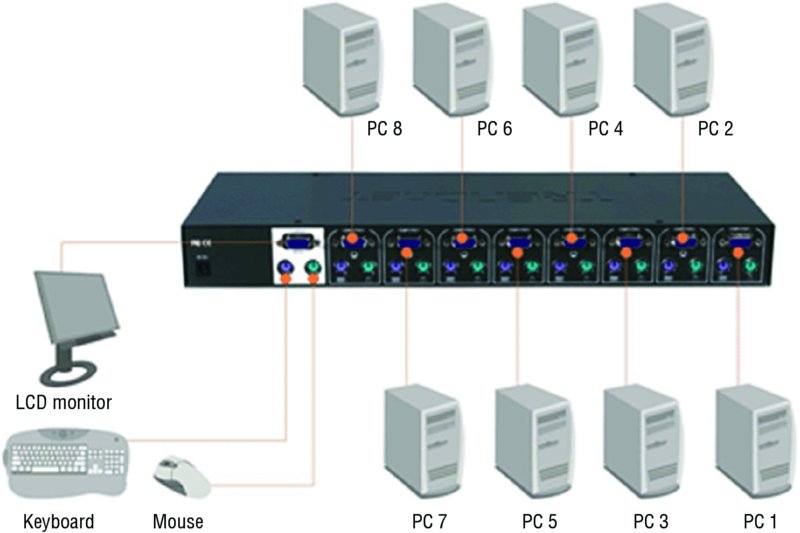
Figure 2.12 Standard KVM switch
Serial
Although serial connections have been largely replaced by the use of KVM switches, it is still possible to connect to a server using a serial connection. The issue that arises is that even if a technician’s laptop had a serial port (which is unlikely today), there would be at most one. This conundrum led to the development of the serial device server. It provides a number of serial ports, which are then connected to the serial ports of other equipment, such as servers, routers, or switches. The consoles of the connected devices can then be accessed by connecting to the console server over a serial link such as a modem, or over a network with terminal emulator software such as Telnet or SSH, maintaining survivable connectivity that allows remote users to log in the various consoles without being physically nearby. This arrangement is shown in Figure 2.13. One of the advantages of this is the ability to get to the servers “out of band.” This means even if the network is down, servers can be reached through the serial ports either locally or through the modem.

Figure 2.13 Serial device server
Virtual Administration Console
To manage servers in a virtual environment, vendors of virtualization software provide administration consoles that allow for one server to another for the purpose of maintenance and administration. Examples include the VMware Server Console and the Virtual Machine Manager Console in Windows Hyper-V.
In Figure 2.14, an example of the VMware Server Console is shown. Here the System Monitor page shows the workload on a specific virtualization host (more on virtualization later, but a host is a physical machine that has multiple virtual machines on it). You can see there are four VMs hosted by server, all of which are currently powered off. That would explain why only 2 percent of CPU and only 1.3 GB of memory are being used, none it by the VMs.

Figure 2.14 VMware Server Console
The Virtual Machine Manager (VMM) Console in Hyper-V is shown in Figure 2.15. It also allows for managing the servers centrally from this console. Here two VMs are shown on the host named Hypervisor8. One of the two VMs is 90 percent through the creation process whereas the other is stopped.

Figure 2.15 VMM in Windows Hyper-V
Network-Based Hardware Administration
Although some of the management of servers may occur locally, most of the time you will find yourself connecting to the servers over the IP-based network. A number of options are available to accomplish this. In this section, we’ll talk about managing the hardware of the server using network-based administration.
KVM over IP
Earlier you learned about using a basic KVM switch. KVM vendors have responded to the need for a KVM switch that can be accessed over the network. The switch is like the one you saw earlier with one difference—it can be reached through the network, as shown in Figure 2.16. This means it is accessible not only from a workstation in the next room, but from anywhere. In this particular implementation (it can be done several ways), each server has a small device between it and the KVM switch that accepts the serial and keyboard/mouse connections.

Figure 2.16 KVM over IP
iLO
Integrated Lights-Out (iLO) is technology embedded into Hewlett-Packard (HP) servers that allows for out-of-band management of the server. Out-of-band management refers to any method of managing the server that does not use the network.
The physical connection is an Ethernet port that will be on the server and will be labeled iLO. In Figure 2.17, one of these iLO ports is shown in an HP Moonshot chassis (these hold blade servers). HP iLO functions out-of-the-box without additional software installation regardless of the server’s state of operation, giving you complete access to the server from any location via a web browser or the iLO Mobile App.

Figure 2.17 iLO port
iDRAC
A Dell Remote Access Controller (DRAC) card provides out-of-band management for Dell servers. The iDRAC refers to a version of these interface cards that is integrated on the motherboard of the server. There will be a port on the back of the server that looks like an Ethernet port that functions as the iDRAC port. In Figure 2.18 it is labeled the designated system management port.

Figure 2.18 iDRAC port
Once configured, the port will present the technician with an interface on their computer, which is connected to the port when the connection is established. This console interface is shown in Figure 2.19.

Figure 2.19 iDRAC console
Network-Based Operating System Administration
When you need to make changes to the operating system, there are a number of ways in which you can remotely make a connection. In this section, we’ll survey the most popular methods of accomplishing network-based operating system administration.
RDP
Developed by Microsoft, Remote Desktop Protocol (RDP) allows you to connect to remote computers and run programs on them. When you use RDP, you see the desktop of the computer you’ve signed into on your screen. The computer at which you are seated is the client and the computer you’re logging into is the server. The server uses its own video driver to create video output and sends the output to the client using RDP. All keyboard and mouse input from the client is encrypted and sent to the server for processing. RDP also supports sound, drive, port, and network printer redirection.
A tool that can be used for this is the Microsoft Remote Desktop Connection Manager (RDCMan). It is a handy console, as shown in Figure 2.20. Note it is not limited to managing Microsoft servers and clients can be found for non-Microsoft systems.

Figure 2.20 RDCMan
SSH
If you don’t need access to the graphical interface and you just want to connect to a server to operate at the command line, you have two options: Telnet and SSH. Telnet works just fine, but it transmits all of the data in cleartext, which obviously would be a security issue. Therefore, the connection tool of choice has become Secure Shell (SSH). It’s not as easy to set up because it encrypts all of the transmissions and that’s not possible without an encryption key.
Although the commands will be somewhat different based on the operating system, you must generate a key, which is generated using some unique information about the server as seed information, so that the key will be unique to the server (the encryption algorithm will be well known). Once configured, the connection process will be very similar to using Telnet, with the exception, of course, that the transmissions will be protected.
VNC
Another remote administration tool that functions like RDP is Virtual Network Computing (VNC). It differs in that it uses the Remote Framebuffer (RFB) protocol. It operates like RDP with respect to the experience, but it is not a secure protocol. It doesn’t transmit in cleartext, but cracking the password is possible if the encryption key and the password are captured. Therefore, strong passwords should be used, and it may be advisable to tunnel it over a VPN or SSH connection.
Command Line or Shell
A shell is a type of user interface that may or may not be graphical. In most cases shells are command-driven interfaces. There are many shells for Unix systems. They all have their own command, syntax, and capabilities. Some operating systems have a single shell—for example, the MS-DOS program. Other Windows systems have multiple shells that can be used such as PowerShell. Devices like routers and switches also have shells like the Cisco IOS. When used over the network, shells are sometimes referred to as remote shells.
Purpose and Operation of Virtualization Components
In today’s networks you must understand virtualization. Organizations large and small are moving to take advantage of the benefits of this technology. They are saving power, consolidating, and downsizing (some would say right-sizing) their physical footprint and suffering far fewer bottlenecks caused by resource limitations. This section introduces you to the components that make virtualization work and the specific role each component plays in making these benefits possible.
Hosts and Guests
The foundation of virtualization is the host device, which may be a workstation or a server. This device is the physical machine that contains the software that makes virtualization possible and the containers, or virtual machines, for the guest operating systems. The host provides the underlying hardware and computing resources, such as processing power, memory, disk, and network I/O, to the VMs. Each guest is a completely separate and independent instance of an operating system and application software.
The host is responsible for allocating compute resources to each of the VMs as specified by the configuration. The software that manages all of this is called the hypervisor. Based on parameters set by the administrator, the hypervisor may take various actions to maintain the performance of each guest as specified by the administrator. Some of these actions may include
- Turning off a VM if not in use
- Taking CPU resources away from one VM and allocating them to another
- Turning on additional VMs when required to provide fault tolerance
The exact nature of the relationship between the hypervisor, the host operating system, and the guest operating systems depends on the type of hypervisor in use. Later on in this section that will be clearer when you learn about hypervisors. From a high level the relationship is shown in Figure 2.21.

Figure 2.21 Hosts and guest
Management Interface for Virtual Machines
One of the benefits of virtualization products such as VMware vSphere, Microsoft Hyper-V, and Oracle VM VirtualBox is the management interface they provide. These interfaces allow you to create, view, and make changes to VMs. Some of these changes can be done when the device is running, and some require shutting the VM down. The VMware Server Console was shown earlier in this chapter in Figure 2.14, in the section “Virtual Administration Console.” In the same section, in Figure 2.15 was the Microsoft Virtual Machine Manager (VMM) Console in Hyper-V. Figure 2.22 shows Oracle VM VirtualBox management console. In this console you can see there are three VMs. We’ve highlighted the VM named test2, and the details about the resources of that VM appear in the details pane.

Figure 2.22 Oracle VM VirtualBox
Hypervisor
Earlier you learned that the exact nature of the relationship between the hypervisor, the host operating system, and the guest operating systems depends on the type of hypervisor in use. There are three types of hypervisors in use today. Let’s review them now.
Type I
A Type I hypervisor (or native, bare-metal) runs directly on the host’s hardware to control the hardware and to manage guest operating systems. A guest operating system runs on another level above the hypervisor. Examples of these are VMware vSphere and Microsoft Hyper-V.
Type II
A Type II hypervisor runs within a conventional operating system environment. With the hypervisor layer as a distinct second software level, guest operating systems run at the third level above the hardware. VMware Workstation and VirtualBox exemplify Type II hypervisors. A comparison of the two approaches is shown in Figure 2.23.

Figure 2.23 Type I and II hypervisors
Hybrid
In the datacenter you will most likely encounter Type I hypervisors, but you should be aware of an emerging type of hypervisor: the hybrid. This is basically a Type II hypervisor, but it is integrated with a cloud. The best example of this is VMware Workstation version 12. With this version, it is possible to connect to vCloud Air or to any private cloud and upload, run, and view VMs from the Workstation interface.
Another new approach that might be considered a hybrid is container-based virtualization. Container-based virtualization is also called operating system virtualization. This kind of server virtualization is a technique where the kernel allows for multiple isolated user-space instances. The instances are known as containers, virtual private servers, or virtual environments.
In this model, the hypervisor is replaced with operating system–level virtualization, where the kernel of an operating system allows multiple isolated user spaces or containers. A virtual machine is not a complete operating system instance but rather a partial instance of the same operating system. The containers in Figure 2.24 are the blue boxes just above the host OS level. Container-based virtualization is used mostly in Linux environments, and examples are the commercial Parallels Virtuozzo and the open source OpenVZ project.

Figure 2.24 Container-based virtualization
Hardware Compatibility List
When choosing the host (server) for a virtualization solution, you should consider the hardware required to achieve the most benefit from the solution. Review the compatibility guides offered by the major vendors: VMware, Citrix (XenServer), and Microsoft. These guides can offer critical guidance with respect to the hardware required by their solutions based on your specific requirements. Having said that, there are some general features and components that are worth mentioning due to their importance. The following sections cover some of these.
BIOS/UEFI Compatibility and Support
In many cases the motherboard and associated BIOS/UEFI settings need no alteration to provide services to virtual machines. However, some of the virtualization products, such as Microsoft Hyper-V, require that the motherboard support hardware-assisted virtualization. This is because in these cases the virtualization product is not installed on top of a regular operating system but instead is installed directly on bare metal—that is, as an integral part of the operating system, as in Windows Server 2012 R2.
The benefit derived from using hardware-assisted virtualization is it allows the hypervisor to dynamically allocate memory and CPU to the VMs as required. When the motherboard and the BIOS support this technology, you must ensure that it is enabled. Figure 2.25 shows an example of the settings. Although most new servers will support hardware-assisted virtualization, it is a feature and a consideration you should know about.

Figure 2.25 Enabling hardware-assisted virtualization
CPU Compatibility Support
One of the key issues to consider when reviewing compatibility guides is the CPU. This component plays a critical role in the overall success of the virtualization solution. You should not only ensure that the CPU you are considering or that is present in the candidate host machine is listed on the compatibly list, but you should also make every effort to use a CPU that supports instruction extensions and features designed to enhance virtualization. Let’s look at two major vendors and their technologies.
AMD-V and Intel VT
CPUs come with varying abilities to support or enhance virtualization. Intel provides an entire line of processers that support what they call Intel Virtualization Technology. The benefits derived from using a CPU with this technology include
- Acceleration of fundamental virtualization processes throughout the platform
- Reduced storage and network latencies, with fewer potential bottlenecks
- The enhanced security that a solid hardware foundation provides
- Improved short- and long-term value from your software and server investments
AMD has a similar line of processors with a technology they call AMD Virtualization (AMD-V). It adds to the instruction set of the CPU and provides many of the same benefits as the Intel technology.
Resource Allocation Between Guest and Host
One of the issues you need to understand is how the host system and the guest operating systems share resources. Keep in mind that the host and the guests are all sharing the same physical resources (CPU, memory, disk, NIC). This is an advantage of a Type 1, or bare-metal hypervisor. There is no underlying operating system using resources. The resources that are allocated to the VMs are called virtual resources, the number of which need not match the number of physical resources in the host machine. For example, the host may have two processors, yet you could assign four virtual CPUs to the guest. Having said that, according to best practices you probably shouldn’t do that. The exact manner in which the resources are assigned and the way in which the administrator uses these assignments to arbitrate use of the physical resource depends on the resources. Let’s look at the way the four major resources are allocated in a virtual environment.
CPUs
You can control the allocation of physical CPU(s) use in one of three ways:
Shares Values such as Low, Normal, High, and Custom (using VMware as an example) are compared to the sum of all shares of all VMs on the server. Therefore, they define the relative percentage each VM can use.
Reservation Guaranteed CPU allocation for a virtual machine.
Limit Upper limit for a virtual machine’s CPU allocation.
These settings are used to ensure that the desired VMs have priority to the CPU (shares), that certain VMs are always guaranteed CPU time (reservations), and that no single VM monopolizes the CPU (limits). In Figure 2.26, you can see how this is done in Microsoft Hyper-V. Although the terminology is slightly different, the concepts are the same. As this figure shows, you can assign multiple virtual CPUs to a VM, which is another way to influence the VMs’ performance.
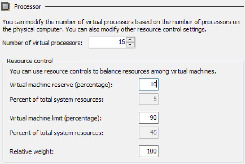
Figure 2.26 Setting CPU allocations in Hyper-V
Storage
A benefit of virtualization is the ability of VMs to share storage. This storage can be located in a single storage device or appliance, or it can be located on multiple storage devices. By logically centralizing the storage and managing it centrally, you reduce the waste that formerly occurred when each server used its own storage.
Increasingly, storage is presented to the VMs as local storage but is actually located in either a storage area network (SAN) or on network-attached storage (NAS). A SAN is a high-performance data network separate from the LAN, and NAS is a storage device or appliance that resides on the LAN.
The VMs reside on the host servers and the host servers are attached to the shared storage devices, as shown in Figure 2.27. Conceptually, the shared storage could be either NAS or a SAN, the difference being that, with a SAN, the servers will need to have a host bus controller card installed that can connect the server to the fiber network that typically comprises the SAN.

Figure 2.27 Shared storage
One of the benefits of shared storage is more efficient use of the storage, with less storage sitting idle while other storage is stressed. When you create VMs, one of the steps involves the creation of a virtual hard drive for the VM. This is space in the shared storage for keeping the image of the VM. There are several types of virtual disks you can create, and some types have unique abilities that aid in this efficient use of space. Every virtualization vendor attaches somewhat different names for these, but they all offer the same basic types. As an example, we’ll look at the types offered by VMware, the market leader in virtualization.
Thick Provision Lazy Zeroed This is analogous to the classic regular hard drive with one exception. Like the classic disk, space required for the virtual disk is allocated during creation. If data is present on the disk, it is not deleted until the space is needed for new data.
Thick Provision Eager Zeroed This is like lazy zeroed but any data on the disk is zeroed out ahead of time. This means it takes longer to create one of these disks.
Thin Provision This is where the disk efficiency comes in. At first, a thin-provisioned disk uses only as much datastore space as the disk initially needs. If the thin disk needs more space later, it can grow to the maximum capacity allocated to it.
In Figure 2.28, you can see how this is done in Hyper-V, and although the terminology is slightly different, the concepts are the same with most vendors. As this figure shows, you can create what is called a differencing disk. This disk type is not unique to Hyper-V. It is used to store changes made to an image when you decide to keep a copy of a previous version of the image. This is what allows for the process of rolling back an image after making changes that you would like to reverse. This makes virtualization perfect for testing changes before an enterprise rollout.

Figure 2.28 Creating a virtual disk in Hyper-V
Memory
Memory resources for a virtual machine are allocated using reservations, limits, and shares, much in the same way as CPU time. A virtual machine can use three user-defined settings that affect its memory resource allocation.
Limit Limits the consumption of memory for a virtual machine. This value is expressed in megabytes.
Reservation Guarantees a minimum allocation for a virtual machine. The reservation is expressed in megabytes.
Shares Represent a relative metric for allocating memory capacity. The more shares a virtual machine is assigned, the more often it gets a time slice of a memory when there is no memory idle time.
In Citrix XenServer, you can use Dynamic Memory Control, which permits the memory utilization of existing VMs to be compressed so that additional VMs can boot on the host. Once VMs on that host are later shut down or migrated to other hosts, running VMs can reclaim unused physical host memory. You enable Dynamic Memory Control by defining minimum and maximum memory settings for virtual machines, as shown in Figure 2.29. In VMware, this concept is called overcommitting memory.

Figure 2.29 Citrix dynamic memory allocation
Network Connectivity
It is possible to connect VMs together in a network and that network can be the same network as the LAN or separate from the LAN. The network can have Internet access or not, depending on how you use the virtual networking components at your disposal. Some of the ways you can connect VMs to the host, to one another, and to devices “outside the box” are covered in this section.
Direct Access (Bridging) vs. NAT
There are two basic options for connecting the VM to the host machine:
- Direct access (bridging), which uses the physical NIC on the host system.
- Network Address Translation (NAT), which creates a private network on the host system, with the host system acting as a DHCP server. When access to networks beyond this private network is required, the host will perform NAT on the private IP address and use its own IP address.
The easiest configuration is to bridge the VM to use the NIC of the host and use its own IP address. But if you want the IP address of the VM to be hidden, then using NAT will ensure that all packets coming from either the VM or its host will appear to come from the host.
If you want to create a network in which the VMs can reach one another, you can use either configuration. Figure 2.30 shows that both methods can be used in the host. You see that some of the hosts are using NAT, which is why they have IP addresses that are used on the LAN, whereas one of the VMs has been bridged and thus does not have an IP address that works on the LAN.

Figure 2.30 NAT vs. bridged
Virtual NICs
You’ve probably already put this together from the our earlier discussions on virtual networking, but to enable a VM to communicate on either the LAN or a private virtual network you must assign it a virtual NIC (vNIC). Multiple vNICs can be added to the same VM for fault tolerance or not of load balancing. Once the vNIC is added, you assign it to a network.
Virtual Switches
To create a virtual network as discussed in the previous section, you have to create a virtual switch that will interconnect the VMs and the host. The vNICs of the VMs are connected to the virtual switch, which in turn (if desired) is connected to the physical NIC on the host, as shown in Figure 2.31. Notice that one of the switches is connected to the LAN and other is not.

Figure 2.31 vSwitch
When creating a vSwitch, you can choose whether or not to connect the vSwitch to a physical NIC. In Figure 2.32, a vSwitch created in VMware indicates there are two physical adapters available to assign to this switch.

Figure 2.32 Assigning a vSwitch to physical adapters
Video
In a virtual desktop infrastructure (VDI), VMs are used to house images that are used by users as their desktops. One of the pain points often experienced when implementing VMs in this fashion is poor video performance: screens that are slow to drag, changes to the display that occur slowly, and other issues that crop up.
This issue is not limited to a VDI but is common to it. Use the video adapter settings of the VM to increase the video memory of the problematic VM, as shown in Figure 2.33. In cases where this must be done to a large number of VMs, you can use a PowerShell script to change them all.

Figure 2.33 Increasing video memory
Summary
In this chapter you learned how to install and configure server operating systems, including key steps like updating firmware, configuring the BIOS/UEFI, preparing the disk, and connecting the server to the network. You also learned about the various ways you can manage the server, both locally and across the network. Finally, we covered the basics of virtualization, including the relationship between host and guest, the role of the hypervisor, the types of hypervisors, and how resources are shared by the VMs.
Exam Essentials
Install and configure a server operating system. Describe the steps in the process and identify which are required and which are optional. Understand the importance of creating a performance baseline and hardening the system.
Describe the methods available to manage the server. The local methods include using KVM switches, making serial connections, and in the virtual world, using a virtual administration console. Network methods include using KVM over IP, iLO, and iDRAC.
Identify the components of virtualization and describe their roles. These components include but are not limited to the host and guest, the management interface, and the hypervisor. You should also be able to describe how CPU, memory, and other resources are shared by the VMs.
Review Questions
You can find the answers in the Appendix.
-
Which of the following is not true with respect to UEFI?
- It provides better security by helping to protect the preboot process.
- It provides faster startup and resuming from hibernation times.
- It does not provide support for drives larger than 2.2 terabytes (TB).
- It supports modern, 64-bit firmware device drivers.
-
Which RAID type provides no fault tolerance?
- RAID 0
- RAID 1
- RAID 3
- RAID 5
-
Which of the following is a Microsoft filesystem?
- ext2
- NTFS
- ReiserFS
- UFS
-
Which filesystem was created by Sun Microsystems?
- ext2
- ZFS
- ReiserFS
- UFS
-
Where is the swap file located?
- In memory
- In the L1 cache
- On the hard drive
- Across the network
-
Which of the following is not a part of hardening the system?
- Disabling all unused services
- Uninstalling unneeded applications
- Ensuring all patches are installed
- Ensuring sufficient processing power
-
What tool is used in Windows Server 2012 R2 to create a baseline?
- Performance Monitor
- Action Center
- System Information
- Event Viewer
-
What is another term for a swap file?
- vDisk
- Pagefile
- Virtual RAM
- Checkpoint file
-
How large should the pagefile be on a Windows server that is not a database server?
- Half the size of RAM
- Equal to the size of RAM
- 1.5 times the size of RAM
- Twice the size of RAM
-
What Windows tool can be used to create and deploy images?
- WDS
- NFS
- PXE
- DAV
-
Which of the following is an industry standard client-server interface that allows networked computers that are not yet loaded with an operating system to be configured and booted remotely by an administrator?
- DNS
- PXE
- iDRAC
- NBP
-
Which device allows you to plug multiple PCs (usually servers) into the device and to switch easily back and forth from system to system using the same mouse, monitor, and keyboard?
- ILO
- iDRAC
- KVM
- vSwitch
-
Which technology is found on HP servers?
- iLO
- iDRAC
- vSwitch
- VMM
-
What Microsoft technology allows you to connect to remote computers and run programs on them?
- iDRAC
- RDP
- KVM
- SSL
-
What vendor creates iDRAC cards?
- EMC
- Dell
- HP
- Cisco
-
Which of the following uses the Remote Framebuffer (RFB) protocol?
- VNC
- RDP
- iDRAC
- ILO
-
Which remote management technology is not graphical in nature?
- VNC
- SSH
- RDP
- Shell
-
Which statement is true with respect to hypervisors?
- Type II is called native.
- Type II runs directly on the host’s hardware.
- A Type II hypervisor runs within a conventional operating system environment.
- VMware Workstation and VirtualBox exemplify Type I hypervisors.
-
Which technique is used to allocate relative access to the CPU among VMs?
- Reservations
- Limits
- Shares
- Time slots
-
Which RAID type is also called mirroring?
- RAID 0
- RAID 1
- RAID 3
- RAID 5