Chapter 7. The Basics: Principal Configuration Tasks for the NAM and NAS
This chapter covers the following topics:
- Understanding the Basic Cisco NAC Appliance Concepts
- NAM Overview
- NAS Overview
- Configuring NAS Deployment Mode
- Understanding NAS Management Within the NAM GUI
- Adding Additional NAS Appliances
This chapter explains the basic configuration tasks required to install and configure the NAC Appliance Manager (NAM) and NAC Appliance Server (NAS).
The NAM and NAS are software packages that are installed on top of their own dedicated server appliance. The software is built on a hardened Linux kernel and will turn each dedicated server into a Cisco appliance. This means you cannot install any other third-party software on top of the Linux kernel. Prior to 4.0.3, you could buy the software from Cisco and install them on top of Cisco-certified servers or buy both software and hardware from Cisco directly to avoid any unexpected hardware and software incompatibilities. From 4.0.3 on, all new NAC 33xx appliance series have come with software preinstalled from Cisco. This means that you only have to apply new updates and patches when you receive your 4.0.3 or higher appliances.
Understanding the Basic Cisco NAC Appliance Concepts
A Cisco NAC Appliance solution consists of NAM, NAS, and Cisco Clean Access (CCA) Agent. The majority of the configurations are performed in NAM because it oversees all deployed NAS appliances and agents. Installation and configuration of NAM and NAS are very straightforward. Here is a high-level summary of how to perform the initial installation and configuration:
Step 1. Connect a keyboard and monitor to NAM and NAS. The mouse is not required. There is no need to plug either appliance into the network yet. An alternative to the keyboard and monitor is using the serial console connection.
Step 2. Insert the NAC Appliance installation CD into the NAM or NAS appliance.
Step 3. Reboot.
Step 4. Follow the step-by-step command-line interface (CLI) setup script to configure NAM and NAS.
Step 5. Connect NAM and NAS to the network and verify connectivity.
NAM Overview
NAM is the central administration server for monitoring and configuring the deployment of NAC Appliance servers and agents. This section covers details on NAM installation, connection, and initial configuration. It also covers NAC Appliance licensing and the NAM GUI.
NAM Hardware Installation Requirements
For performance reasons, it is generally a good idea to acquire servers that exceed the minimum required hardware specifications in any enterprise deployments. For the NAM, two physical 10/100/1000 Ethernet interfaces are required for a high-availability (HA) deployment. For non-HA deployments, only one physical interface is needed. In either deployment scenario, Ethernet 0 is the primary network interface. For a NAM HA scenario, Ethernet 1 is the designated failover interface to the standby NAM for failover heartbeats and stateful connection information.
NAM Software Installation Requirements
The software installation requirements are as follows:
- Cisco NAC Appliance – Clean Access CD
- NAM or "CiscoCleanAccess" license key
How to Connect NAM
There are two methods available to connect the NAM initially. Both methods will access the CLI required to perform the initial configuration. Option 1 is the preferred method, but both are listed.
- Connect a keyboard and monitor to the back of the NAM appliance. A mouse is not required.
- Connect a serial cable from a laptop or desktop PC to the serial port (typically DB9 connector) on the NAM appliance. Open a terminal emulation program, such as HyperTerminal or SecureCRT, on the laptop or desktop PC to access the NAM CLI. The port settings for the terminal emulation programs are as follows:
— Bits Per Second – 9600
— Data Bits – 8
— Parity – None
— Stop Bits – 1
— Flow Control – None
— Terminal Emulation – VT100
After the initial configuration is complete and NAM is connected to the network, you can securely connect to NAM via common browsers such as Internet Explorer (IE) or FireFox using https://NAM_IP_address. An example is https://192.168.137.4.
Performing Initial NAM Configurations
If your NAM is preinstalled with the NAM software from Cisco, you may skip the manual installation that follows and proceed from Example 7-3. From the CLI, simply type in service perfigo config to run the setup script.
If your NAM is not preinstalled with the NAM software from Cisco, you will need to manually install the NAM software via the Cisco NAC Appliance – Clean Access CD. Insert the NAC installation CD into the CD-ROM drive of the NAM appliance and reboot the appliance.
Your NAC appliance should boot from the CD-ROM and display the NAC installation display. Example 7-1 shows the NAC installation output.
Example 7-1. Initial NAC Installation Output
Cisco Clean Access 4.0-3 Installer (C) 2006 Cisco Systems, Inc.
Welcome to the Cisco Clean Access 4.0-3 Installer!
- To install a Cisco Clean Access device, press the <ENTER> key.
- To install a Cisco Clean Access device over a serial console,
enter serial at the boot prompt and press the <ENTER> key.
boot:
Pressing <ENTER> key at the above boot prompt will continue the NAC installation via
keyboard, monitor, and mouse. Entering the word, serial, at the boot prompt will
continue via the serial cable.
There will be a large amount of installation data being displayed on screen. Since
this is an installation example, only the interactive portions of the installation
will be shown here.
The next interactive installation point is where you the administrator need to choose
the NAM or NAS. Choose CCA Manager and press OK. Pressing the Tab key on your keyboard
should allow you to jump to the OK button.
Welcome to Cisco Clean Access
++ Package Group Selection ++
| |
| Total install size: 678M |
| |
| [*] CCA Manager |
| [ ] CCA Server |
| |
| |
| |
| |
| |
| |
| |
| +----+ +--------+ |
| | OK | | Cancel | |
| +----+ +--------+ |
| |
| |
+---------------------------+
<Space>,<+>,<->selection | <F2> Group Details | <F12> next screen
Next, you will see the HDD formatting portion, as displayed in Example 7-2. Don't be alarmed if the formatting process stops at 11% for a while. The total amount of formatting time will depend on the HDD space of the appliance. Be patient. Give yourself about an hour or so to complete the entire installation process.
Example 7-2. NAC Manager Installation Screen
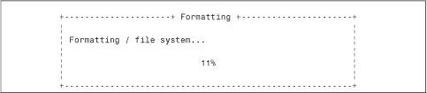
Next, you will see many more Package Installation messages with filename info, size, time remaining, and so forth on your screen. Be patient, and it will eventually finish. When complete, you should see the setup script walking you through the configuration of the NAM. Example 7-3 shows the NAM setup/configuration script. Simply follow the script through.
Note
By default, the NAM Installation software assigns private IP addresses to all required IP address fields. Enter your own IP addresses for your network.
If you have completed the setup and configuration script and need and decide to reconfigure certain parameters, simply access the CLI via Secure Shell (SSH); keyboard, monitor, and mouse; or serial console, and type service perfigo config to rerun the script. Although not required, Cisco best practices recommend that the administrator reboot the NAM after making any changes in the setup script.
Example 7-3. NAM Setup/Configuration Script
Welcome to the Cisco Clean Access Manager quick configuration utility.
Note that you need to be root to execute this utility.
The utility will now ask you a series of configuration questions.
Please answer them carefully.
Cisco Clean Access Manager, (C) 2006 Cisco Systems, Inc.
Configuring the network interface:
Please enter the IP address for the interface eth0 [10.0.2.15]: 192.168.137.3
You entered 192.168.137.3 Is this correct? (y/n)? [y]
Please enter the netmask for the interface eth0 [255.255.255.0]:
You entered 255.255.255.0. Is this correct? (y/n)? [y]
Please enter the IP address for the default gateway [192.168.137.1]:
You entered 192.168.137.1. Is this correct? (y/n)? [y]
Please enter the hostname [localhost.localdomain]: nam1
You entered nam1. Is this correct? (y/n)? [y]
Please enter the IP address for the name server: [10.0.2.1]: 192.168.100.100
You entered 192.168.100.100. Is this correct? (y/n)? [y]
The shared secret used between Clean Access Manager and Clean Access Server is the
default string: cisco123
This is highly insecure. It is recommended that you choose a string that is unique
to your installation.
Please remember to configure the Clean Access Server with the same string. Please
enter the shared secret between Clean Access Serv3
You entered: cisco123
Is this correct? (y/n)? [y] y
>>> Configuring date and time:
The timezone is currently not set on this system.
Please identify a location so that time zone rules can be set correctly.
Please select a continent or ocean.
1) Africa
2) Americas
3) Antarctica
4) Arctic Ocean
5) Asia
6) Atlantic Ocean
7) Australia
8) Europe
9) Indian Ocean10) Pacific Ocean
11) none - I want to specify the time zone using the Posix TZ format.
#? 2
Please select a country.
1) Anguilla 18) Ecuador 35) Paraguay
2) Antigua & Barbuda 19) El Salvador 36) Peru
3) Argentina 20) French Guiana 37) Puerto Rico
4) Aruba 21) Greenland 38) St Kitts & Nevis
5) Bahamas 22) Grenada 39) St Lucia
6) Barbados 23) Guadeloupe 40) St Pierre & Miquelon
7) Belize 24) Guatemala 41) St Vincent
8) Bolivia 25) Guyana 42) Suriname
9) Brazil 26) Haiti 43) Trinidad & Tobago
10) Canada 27) Honduras 44) Turks & Caicos Is
11) Cayman Islands 28) Jamaica 45) United States
12) Chile 29) Martinique 46) Uruguay
13) Colombia 30) Mexico 47) Venezuela
14) Costa Rica 31) Montserrat 48) Virgin Islands (UK)
15) Cuba 32) Netherlands Antilles 49) Virgin Islands (US)
16) Dominica 33) Nicaragua
17) Dominican Republic 34) Panama
#? 45
Please select one of the following time zone regions.
1) Eastern Time
2) Eastern Time - Michigan - most locations
3) Eastern Time - Kentucky - Louisville area
4) Eastern Time - Kentucky - Wayne County
5) Eastern Standard Time - Indiana - most locations
6) Eastern Standard Time - Indiana - Crawford County
7) Eastern Standard Time - Indiana - Starke County
8) Eastern Standard Time - Indiana - Switzerland County
9) Central Time
10) Central Time - Michigan - Wisconsin border
11) Central Time - North Dakota - Oliver County
12) Mountain Time
13) Mountain Time - south Idaho & east Oregon
14) Mountain Time - Navajo
15) Mountain Standard Time - Arizona
16) Pacific Time
17) Alaska Time
18) Alaska Time - Alaska panhandle
19) Alaska Time - Alaska panhandle neck
20) Alaska Time - west Alaska
21) Aleutian Islands
22) Hawaii
#? 16
The following information has been given:
United States
Pacific Time
Is the above information OK?
1) Yes
2) No
#? 1
Updating timezone information...
Current date and time hh:mm:ss mm/dd/yy [05:50:43 12/06/06]:
You entered 05:50:43 12/06/06 Is this correct? (y/n)? [y]
Wed Dec 6 05:50:43 PST 2006
You must generate a valid SSL certificate in order to use the Clean Access Manager's
secure web console.
Please answer the following questions correctly.
Information for a new SSL certificate:
Enter fully qualified domain name or IP: nam1.selab.net
Enter organization unit name: selab
Enter organization name: se_org
Enter city name: san jose
Enter state code: ca
Enter 2 letter country code: us
You entered the following:
Domain: cam1.selab.net
Organization unit: selab
Organization name: se_org
City name: san jose
State code: ca
Country code: us
Is this correct? (y/n)? [y]
Generating SSL Certificate...
CA signing: /root/.tomcat.csr -> /root/.tomcat.crt:
CA verifying: /root/.tomcat.crt <-> CA cert
/root/.tomcat.crt: OK
Done
For security reasons, it is highly recommended that you change the default passwords
for the root user.
User: root
Changing password for user root.
New UNIX password: ********
Retype new UNIX password: ********
passwd(pam_unix)[2087]: password changed for root
passwd: all authentication tokens updated successfully.
Changes require a RESTART of Clean Access Manager.
Configuration is complete.
Logrotate configuration
Initializing Clean Access Manager Database...
Done
Install has completed. Press <ENTER> to reboot.
NAC Licensing
After setting up NAM and accessing the GUI (https://NAM_IP) for the first time, you will be prompted to enter a valid product license. Without it, you cannot proceed with further NAC configurations. See Figure 7-1 for initial license installation.
Figure 7-1. NAC Manager Licensing Page
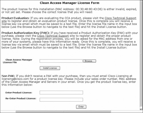
There are two available licensing options.
- Clean Access FlexLM License Files If you have a product activation key from your order, go to http://www.cisco.com/go/license with your Cisco.com ID and enter the PAK to receive a license file via e-mail. You will have to enter the MAC address of the primary NAM Ethernet0 interface. For failover, you will have to enter the Ethernet0 MAC address of the backup NAM as well. After you have the license file on your computer, click the Browse button to locate the license file on your computer and then Install License.
- Perfigo Product License Key Legacy Pre-Cisco license key format. If you have a legacy key, you can enter it at the bottom where it states Enter Product License. Then click Enter.
After the license file or legacy product license is installed, you will be redirected to the admin login page of NAM. The default NAM login is admin/cisco123.
For future license additions and updates, simply go to Administration > CCA Manager > Licensing and upload additional licenses. See Figure 7-2 for updated licenses.
Figure 7-2. NAM Licensing Page with Installed Server Count

NAM GUI Description
After the initial licensing, all NAM configurations are performed via a secured web browser session at https://NAM_IP. Figure 7-3 shows the initial NAM login screen.
Figure 7-3. Initial NAM Login Screen
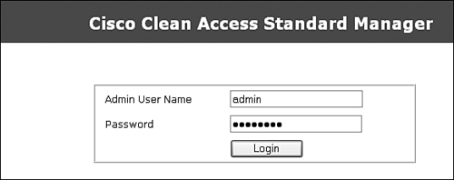
After you enter the NAM GUI, you can change the admin account and password under the Administration > Admin Users page. After logging in, the main NAM configuration screen is displayed, as shown in Figure 7-4.
Figure 7-4. Main NAM Configuration Screen

The main NAM configuration screen is divided into five sections on the left side of the screen, as described in Table 7-1.
Table 7-1. NAM Configuration Screen


NAS Overview
NAS is the policy enforcer between the trusted and untrusted networks. This section describes how to install and configure NAS (also known as the CCA server).
NAS Hardware Installation Requirements
Because NAS is the true workhorse of the NAC architecture, it requires high performance hardware. In the In-Band mode, all traffic will pass through NAS between its Untrusted and Trusted Ethernet interfaces. In Out-of-Band mode, only the authentication traffic passes through the NAS. Thus, OOB is typically used for higher-performance LAN deployments.
If HA is desired, three interfaces are required. Ethernet0 is the trusted inside interface. Ethernet1 is the untrusted client networks. The third Ethernet interface is used for failover purposes. An option for the failover interface can be the serial interface on the NAS appliance. However, the third Ethernet interface is recommended for higher-speed transfer of failover data.
Note
For NAM and NAS HA, Cisco recommends enabling and connecting both the Ethernet and serial failover interfaces.
NAS Software Installation Requirements
The only software requirement is the Cisco NAC Appliance – Clean Access CD.
NAS Software License Requirement
There is no license key to enter into the NAS during installation. The NAM controls how many NAS devices can be deployed and managed. All licensing is handled through the NAM licensing GUI.
How to Connect NAS
NAS is configured using the same process as described for the NAM installation, with the following options available:
- Use a keyboard and monitor; no mouse required.
- Connect to NAS via a serial cable from a laptop or desktop PC running HyperTerminal or any other similar terminal emulation application.
After the installation of the NAS software, https://NAS_IP/admin is used to access the NAS directly. An example is https://192.168.137.10/admin.
Performing Initial NAS Configurations
If your NAS is preinstalled with the NAS software from Cisco, you may skip the following manual CD installation discussion and proceed directly to the setup script. To run the setup script from the CLI, simply type in service perfigo config.
If your NAS is not preinstalled with the NAS software from Cisco, you will have to manually install the NAS software via the Cisco NAC Appliance – Clean Access CD. Insert the NAC CD into the CD-ROM drive of the NAM appliance and reboot the appliance.
The NAC Appliance should boot from the CD-ROM and display the NAC installation status. The NAS installation process is very similar to the NAM installation process described earlier. For the sake of conserving space, the full installation process will not be shown here, although Example 7-4 provides a condensed version:
Step 1. Insert the Cisco NAC Appliance – Clean Access CD and reboot NAS Appliance.
Step 2. When prompted to select CCA Manager or CCA Server, choose CCA Server.
Step 3. Be patient. NAS installation can take up to 1 hour. When the setup and configuration script launches, enter all required IP information. The NAS setup script and configuration script is shown in Example 7-4.
Note
If you have completed the setup and configuration script and decide to reconfigure certain parameters, simply access the CLI via SSH, keyboard and monitor, or serial console and type service perfigo config to rerun the script. Cisco best practice recommends a reboot after running the setup script.
Example 7-4. Sample NAS Setup Script
Welcome to the Cisco Clean Access Server quick configuration utility.
Note that you need to be root to execute this utility.
The utility will now ask you a series of configuration questions.
Please answer them carefully.
Cisco Clean Access Server, (C) 2006 Cisco Systems, Inc.
Configuring the network interfaces:
Please enter the IP address for the interface eth0 [10.1.110.2]:
You entered 10.1.110.2. Is this correct? (y/n)? [y]
Please enter the netmask for the interface eth0 [255.255.255.0]:
You entered 255.255.255.0. Is this correct? (y/n)? [y]
Please enter the IP address for the default gateway [10.1.110.1]:
You entered 10.1.110.1. Is this correct? (y/n)? [y]
[Vlan Id Passthrough] for packets from eth0 to eth1 is disabled.
Would you like to enable it? (y/n)? [n]
[Management Vlan Tagging] for egress packets of eth0 is disabled.
Would you like to enable it? (y/n)? [n]
Please enter the IP address for the untrusted interface eth1 [10.1.111.2]:
You entered 10.1.111.2. Is this correct? (y/n)? [y]
Please enter the netmask for the interface eth1 [255.255.255.0]:
You entered 255.255.255.0. Is this correct? (y/n)? [y]
Please enter the IP address for the default gateway [10.1.111.1]:
You entered 10.1.111.1. Is this correct? (y/n)? [y]
[Vlan Id Passthrough] for packets from eth1 to eth0 is disabled.
Would you like to enable it? (y/n)? [n]
[Management Vlan Tagging] for egress packets of eth1 is disabled.
Would you like to enable it? (y/n)? [n]
Please enter the hostname [cas1]:
You entered cas1. Is this correct? (y/n)? [y]
Please enter the IP address for the name server: [10.1.112.105]:
You entered 10.1.112.105. Is this correct? (y/n)? [y]
Would you like to change shared secret? (y/n)? [y]
Please enter the shared secret: cisco123
You entered: cisco123
Is this correct? (y/n)? [y]
>>> Configuring date and time:
The timezone is currently set to:America/Los_Angeles
Would you like to change this setting? (y/n)? [y] n
Current date and time hh:mm:ss mm/dd/yy [14:26:55 12/08/06]:
You entered 14:26:55 12/08/06. Is this correct? (y/n)? [y]
Fri Dec 8 14:26:55 PST 2006
You must generate a valid SSL certificate in order to use the Clean Access Server's
secure web console.
Please answer the following questions correctly.
Information for a new SSL certificate:
Enter fully qualified domain name or IP: cas1.SElab.net
Enter organization unit name: SElab
Enter organization name: SE
Enter city name: San Jose
Enter state code: ca
Enter 2 letter country code: us
You entered the following:
Domain: cas1.SElab.net
Organization unit: SElab
Organization name: SE
City name: San Jose
State code: ca
Country code: us
Is this correct? (y/n)? [y] y
Generating SSL Certificate...
CA signing: /root/.tomcat.csr -> /root/.tomcat.crt:
CA verifying: /root/.tomcat.crt <-> CA cert
/root/.tomcat.crt: OK
Done
For security reasons, it is highly recommended that you change the default password
for the root user.
User: root
Changing password for user root.
New UNIX password:
Retype new UNIX password:
passwd: all authentication tokens updated successfully.
Would you like to change the default password for the web console admin user
password? (y/n)? [y]
Please enter an appropriately secure password for the web console admin user.
New password for web console admin:
Confirm new password for web console admin:
Web console admin password changed successfully.
Configuration is complete.
[root@cas1 ~]#
NAS GUI Description
There are two ways to connect to NAS via the GUI: through the NAM GUI and by connecting directly to the NAS GUI.
To connect to the NAS through the NAM GUI, do the following:
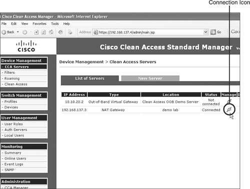
Step 1. Within the NAM interface, select Device Management > CCA Servers.
Step 2. Click the Connection icon under the Manage column. See Figure 7-5.
Figure 7-5. Managing a NAS Within the NAM GUI
To connect to the NAS GUI directly, do the following:
Step 1. Type https://NAS_IP/admin. For example, https://192.168.137.3/admin.
Step 2. When prompted to log in, enter the web console login and password. The default should be admin/cisco123. After you log in, the NAS GUI screen is shown. Within this screen, you can make IP information changes and reboot if necessary. See Figure 7-6 for NAS IP configuration.
Figure 7-6. NAS IP Address Configuration

The Administration panel on the left side is fairly self-explanatory:
- Network Settings Used for IP info, Domain Name System (DNS), and failover changes. For monitoring HA failover, the failover screen here is useful in showing the connection status of this NAS versus the standby NAS. Figure 7-7 shows the NAS Failover GUI status page.
Figure 7-7. NAS Failover Configuration Page

- Software Update Used to update the NAS software. Can also be done from the NAM GUI.
- SSL Certificate Used to generate, import, and export digital certificates. Secure Sockets Layer certificates should typically be generated from the NAM GUI.
- Time Server Used to synchronize NAS with a dedicated NTP server. The NAS and NAM time difference must be less than 5 minutes for NAC to function properly. This is very important.
- Admin Password Update admin password.
The Monitoring panel includes the following:
- Active VPN Clients This feature is used for monitoring RADIUS accounting packets received from the wireless LAN Controller or VPN concentrator. During SSO, the List All VPN Clients button will show info relating to client IP, client name, and the VPN server IP based on the received RADIUS accounting packets.
- Support Logs Very useful for troubleshooting and debugging communications from the clients to NAS and to NAM. Cisco best practices recommend enabling logging levels to ALL only during troubleshooting at the Cisco Technical Assistance Center's request. Set logging level to Severe during normal operations. The Download button allows admins to review local log files for troubleshooting. See Figure 7-8.
Figure 7-8. Viewing and Setting NAS Support Logs

Configuring NAS Deployment Mode
NAS can be deployed in several modes.
In-Band Virtual Gateway (VGW), Real-IP Gateway, or NAT (Network Address Translation) Gateway
Out-of-Band Virtual Gateway, Real-IP Gateway, or NAT Gateway
In-Band Deployment Options
The in-band deployment options are as follows:
- VGW Virtual Gateway is probably the easiest and quickest way to deploy NAC. NAS simply acts as a bridge and policy enforcement gateway between the end clients and the upstream router. Figure 7-9 shows a sample in-band VGW deployment.
Figure 7-9. In-Band VGW Deployment
- Real-IP Real-IP gateway turns the NAS appliance into a routing gateway. Both Ethernet0 (trusted network) and Ethernet1 (Untrusted client network) are assigned unique IP addresses. Static routes are configured within NAS to maintain network connectivity. Figure 7-10 shows a sample in-band Real-IP deployment.
Figure 7-10. In-Band Real-IP Deployment
- NAT Gateway NAT gateway mode is basically the same as the Real-IP mode. The only difference is that private NAT addresses are assigned to the Ethernet1 (untrusted client network) interface. NAS can perform dynamic NAT, one-to-one NAT, or Port Address Translation between the Ethernet0 and Ethernet1 interfaces. However, NAT functionality consumes additional CPU resources and limits the total performance of the NAS Appliance. Figure 7-11 shows an example of an in-band NAT gateway lab-only deployment.
Figure 7-11. In-Band NAT Gateway Lab-Only Deployment

Caution
NAT Gateway mode is not supported in any production environment and should be used only in a controlled lab test network.
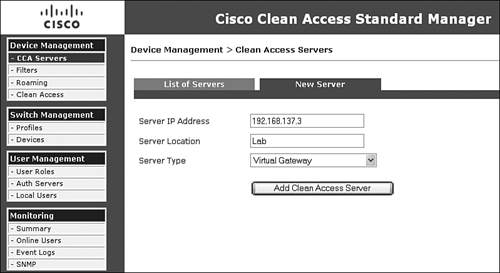
For either an L2 or L3 in-band deployment, the NAS server type is treated the same. Simply select the Server Type as Virtual Gateway, Real-IP, or NAT Gateway. Figure 7-12 shows how to add NAS as a virtual gateway.
Figure 7-12. Adding NAS as a Virtual Gateway
For L3 in-band deployment, meaning there is a router or L3 hop between the clients and the NAS, you must enable the L3 routing check box:
Step 1. Go to Device Management > CCA Servers.
Step 2. Find the NAS or CCA server you added and click the Connection icon under the Manage column. See Figure 7-5.
Step 3. Select the Network tab and check Enable L3 Support. See Figure 7-13.
Figure 7-13. Enabling L3 Support in NAS

Out-of-Band Deployment Options
Out-of-band deployment options are similar to in-band deployment options. Simply select the mode best suited for your environment from the three mode available.
L2 or L3 out-of-band deployments are configured using the same process as L2 or L3 in-band deployments. The only difference is that you must select the Server Type as Out-of-Band <mode>. Figure 7-14 shows how to add NAS as Out-of-Band Virtual Gateway. More details on how to deploy out-of-band can be found in Chapter 10, "Configuring Out-of-Band."
Figure 7-14. Adding NAS as an Out-of-Band Virtual Gateway

Note
Out-of-Band NAT Gateway mode is not supported in any production environment and should be used only in a controlled lab test network.
Understanding NAS Management Within the NAM GUI
All deployed NAS appliances will fall under the administration of one NAM appliance for typical enterprise deployments. Therefore, the administrator can easily deploy configurations to an individual or multiple NAS servers quickly from either global or local policy settings.
Within the NAM configuration page, the administrator can create, modify, and delete policies for all managed NAS servers. Any global settings created within NAM are applied to all NAS servers. Any policies created within a NAS are always local to that NAS and will not be applied as a global policy. Any locally created policies and changes within a NAS override the global setting by the NAM.
Global Versus Local Settings
The concept of global versus local settings can help with quick and efficient NAC deployments. Most parameters are configured globally and automatically applied to all NAS servers.
Global Settings
Global settings include fields that apply to all added NAS servers. Figure 7-15 shows the global settings in the NAM GUI.
Figure 7-15. Global Settings for All NAS Servers

The global parameters are as follows:
- Device Management > Filters This is where you set login and posture assessment exceptions for IP and MAC addresses and subnets. Typically, this is used when specific devices such as IP phones, printers, and other non-NAC responding devices should bypass login and posture assessment. For an IP phone, you can enter its MAC address, select IGNORE under Access Type, and it will bypass NAC. Figure 7-16 shows an IP phone added to the filter list with the IGNORE action assigned to that device.
Figure 7-16. NAC Bypass or Filter Entry GUI

- Device Management > Clean Access > Certified Devices > Certified List The certified devices list shows all authenticated and posture assessed devices. Figure 7-17 has a certified user "jdoe".
Figure 7-17. User "jdoe" Shown as a Certified Device on a Network

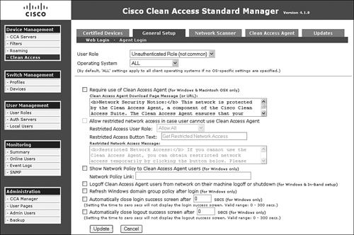
- Device Management > Clean Access > General Setup This is where you set requirements for web login and Clean Access Agent login. Under Clean Access Agent login, if you require all employees with any Windows machine to install the NAC agent on their PC, simply select User Role: Employee, Operating System: WINDOWS_ALL, and check the Require Use of Clean Access Agent box. See Figure 7-18.
Figure 7-18. Web and Agent Login Requirement GUI
- Device Management > Clean Access > Network Scanner This is where you set loading and configuration of the built-in Nessus scanner for web login posture assessments. Figure 7-19 shows the web login scanner configuration page.
Figure 7-19. Network Scanner Configuration GUI for Web Login Users

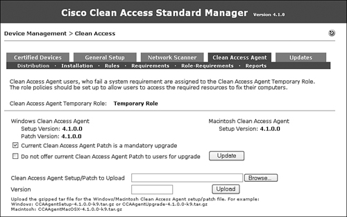
- Device Management > Clean Access > Clean Access Agent Here you configure all NAC compliance policies such as hotfixes, antivirus and antispyware definitions, and so on. This is a very useful page. You will spend some initial setup time here setting up NAC software compliance policies. Figure 7-20 shows a NAC software compliance configuration page.
Figure 7-20. NAC Agent Policy GUI
- Device Management > Clean Access > Updates This shows the version summary of Cisco checks and rules, supported antivirus and antispyware product count, and agent upgrade version info. Figure 7-21 provides an overall summary. All the updates received here come directly from a Cisco server. This helps to keep NAM updated and saves the administrator time from manually going to all supported antivirus and antispyware vendors to download the latest definitions. The same applies to OS hotfixes as well.
Figure 7-21. Summary of Updates for Checks and Rules, Antivirus and Antispyware List, and Clients

- User Management > User Roles Use this section for creating user roles, such as Unauthenticated, Quarantine, Allow All, Guest, and so on, which authenticated users are assigned to. For In-Band mode, traffic control policies and bandwidth per role assignment are configured here. See Figure 7-22.
Figure 7-22. User Roles and Policies Configuration GUI

- User Management > Auth Servers Use this section to define which back-end authentication server will be used to authenticate users. Authentication server types include Kerberos, RADIUS, Window NT, LDAP, Active Directory Single-Sign-On, Windows NetBIOS SSO, Cisco VPN SSO, and Allow All. Figure 7-23 shows four authentication server types. A detailed example of how to configure Active Directory Single-Sign-On is shown in Chapter 11, "Configuring Single Sign-On." You can also test whether your authentication server is configured correctly via the Auth Test tab (not available for Active Directory SSO due to Kerberos implementation).
Figure 7-23. Multiple Authentication Servers Configured

- User Management > Local Users This is where you set the local user database internal to NAM. The guest user is typically created here. This local database is used when an external database is not available. See Figure 7-24 for an example of multiple users created within the local database.
Figure 7-24. Sample User Created Within the NAM Local Database

Local NAS Settings
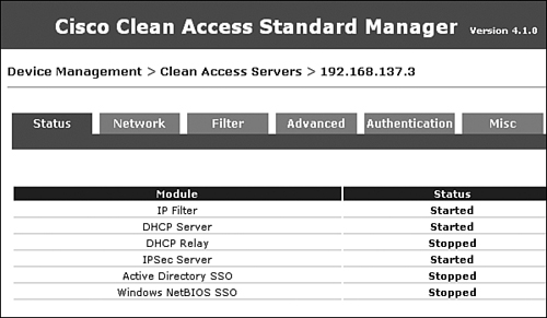
Beyond the global settings you can apply in the NAM GUI, there are local settings you can apply to each NAS in the GUI for that NAS. The word local here refers to all settings that directly apply to the NAS being configured. There is no setting inheritance across multiple NAS appliances. To configure a specific NAS, you would access Device Management > CCA Servers and click the Manage icon for a specific NAS. Figure 7-25 shows the six tabs available for each NAS.
Figure 7-25. NAS Status GUI
The list that follows explains each functional local NAS setting tab and subtab and its use:
- Device Management > CCA Servers > Status As shown in Figure 7-25, the Status tab shows the status of the services running on the NAS.
- Device Management > CCA Servers > Network > IP This is the IP configuration page for trusted and untrusted interfaces. For Layer 3 deployment (one or more router hops between the clients and NAS server), the Enable L3 Support box must be checked. Be sure to click Update after changing or updating settings. NAS will notify you if a reboot is required. See Figure 7-26.
Figure 7-26. NAS IP Configuration GUI

- Device Management > CCA Servers > Network > DHCP > DHCP Status This is where you set NAS DHCP services. If you are keeping your corporate DHCP server in use and not using the NAS DHCP services, make sure to select None. Figure 7-27 shows the NAS DHCP configuration page.
Figure 7-27. NAS DHCP Services Configuration GUI

- Device Management > CCA Servers > Network > DHCP > Subnet List This is the NAS DHCP manual IP subnet creation page.
- Device Management > CCA Servers > Network > DHCP > Reserved IPs This shows a list of MAC addresses associated with reserved IP addresses.
- Device Management > CCA Servers > Network > DHCP > Auto-Generate This allows automatic generation of IP subnets by NAS. The administrator defines the subnet sizes.
- Device Management > CCA Servers > Network > DHCP > Global Options This is where you enable user-specific DHCP options.
- Device Management > CCA Servers > Network > DHCP > Global Action This allows global changes to be made to all DHCP subnets defined on NAS without manually editing each DHCP subnet.
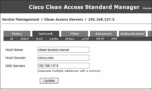
- Device Management > CCA Servers > Network > DNS This is the NAS DNS configuration page. Figure 7-28 shows where you configure the hostname, domain name, and DNS server IP addresses. Make sure to click the Update button after entering DNS information.
Figure 7-28. NAS DNS Configuration GUI
- Device Management > CCA Servers > Network > Certs This is the NAS Certificate import, export, and generation page as shown in Figure 7-29.
Figure 7-29. NAS Certificate Management GUI

- Device Management > CCA Servers > Network > IPsec Deprecated feature in 4.x.
- Device Management > CCA Servers > Network > L2TP Deprecated feature in 4.x.
- Device Management > CCA Servers > Network > PPTP Deprecated feature in 4.x.
- Device Management > CCA Servers > Network > PPP Deprecated feature in 4.x.
- Device Management > CCA Servers > Filter > Devices This is where you set login and posture assessment exceptions for IP and MAC addresses and subnets. Typically, this is used when specific devices such as IP phones, printers, and other non-NAC responding devices should bypass login and posture assessment. For an IP phone, if you enter its MAC address and select IGNORE under Access Type, it will bypass NAC. See Figure 7-16 earlier where non-NAC responding devices can be added to bypass NAC.
- Device Management > CCA Servers > Filter > Subnets Individual IP or IP subnets entered here can be allow, deny, or assigned to specific user roles. "allow" bypasses NAC. deny means no network access through NAS.
- Device Management > CCA Servers > Filter > Roles > Traffic Control This is where you set network access policies assigned to each access role within the selected NAS. Cisco best practices recommend that any policy modifications to any defined roles should be performed at the global level under User Management > User Roles to keep policy administration in one central location.
- Device Management > CCA Servers > Filter > Roles > Allowed Hosts This is where you set hosts allowed during remediation while in the Quarantine or Temporary role. Cisco best practices recommend that any policy modifications to any defined roles should be performed at the global level under User Management > User Roles to keep policy administration in one central location.
- Device Management > CCA Servers > Filter > Roles > Bandwidth This is where you can set bandwidth management per role. This applies only to in-band deployment. Cisco best practices recommend that any policy modifications to any defined roles should be performed at the global level under User Management > User Roles to keep policy administration in one central location.
- Device Management > CCA Servers > Filters > Clean Access > Certified Devices Devices added in this page are exempted from NAC authentication and posture assessment for that specific NAS. Cisco best practices recommend that adding any exempt devices should be performed at the global level.
- Device Management > CCA Servers > Filter > Clean Access > Add Floating Device This is where you can add floating devices that enforce NAC authentication and assessment on a per-session basis for a specific NAS. These devices typically refer to routers, VPN concentrators, or firewall devices that have multiple PCs sitting behind them. Cisco best practices recommend that adding any floating devices should be performed at the global level. See Figure 7-30.
Figure 7-30. Local Floating Devices Added Within a Specific NAS

- Device Management > CCA Servers > Filter > Fallback This is useful when deploying NAS across WAN links to remote sites. This failsafe feature starting in 4.1.0 allows the NAS to allow all, block all, or ignore new connections when NAS loses connectivity to NAM due to WAN failure. Setting Ignore means that no new connections are allowed to pass through the NAS during the WAN failure. See Figure 7-31.
Figure 7-31. NAS Fallback Configuration for Remote Sites Across the WAN

- Device Management > CCA Servers > Advanced > Managed Subnet This is used mostly during L2 deployments. Managed subnets are used anytime NAS's untrusted interface is responsible for specific user VLANs or subnets. NAS creates an Address Resolution Protocol (ARP) entry for that subnet in order to properly communicate within that subnet space. See Figure 7-32.
Figure 7-32. Multiple User VLANs and Subnets Created as Managed Subnets

- Device Management > CCA Servers > Advanced > VLAN Mapping This is for L2 virtual gateway central NAS deployments only. This feature must be configured and enabled for L2 virtual gateway central deployments or there will be unexpected spanning tree behaviors on the network due to network loops. Cisco best practices recommend that VLAN mapping be configured prior to connecting the NAS untrusted Ethernet1 interface on the network to prevent loops. See Figure 7-33 for sample configuration.
Figure 7-33. VLAN Mapping Requirement for L2 Virtual Gateway Central Deployment

- Device Management > CCA Servers > Advanced > NAT This is where you set NAT session timers. Cisco best practices recommend that any NAT functionality within the NAS should be deployed only in lab environments and not production.
- Device Management > CCA Servers > Advanced > 1:1 NAT This is where you set one-to-one NAT configuration. Cisco best practices recommend that any NAT functionality within NAS should be deployed only in lab environments and not production.
- Device Management > CCA Servers > Advanced > Static Routes This is used for all L3 deployments. Because NAS does not support routing protocols, status routes must be configured for network reachability. This feature is not used for L2 deployments. See Figure 7-34.
Figure 7-34. Static Routes Configured for L3 Deployments

- Device Management > CCA Servers > Advanced > ARP This is where you create an ARP entry in the NAS.
- Device Management > CCA Servers > Advanced > Proxy Here you specify proxy server IP/port when NAS is deployed in an HTTP/HTTPS proxy environment. This setting redirects user HTTP requests to the proxy server.
- Device Management > CCA Servers > Authentication > Login Page This is where you set the local NAS login page that can override the global user login page when enabled. See Figure 7-35.
Figure 7-35. Local NAS Login Pages Created for Windows, Mac OS, and Linux

- Device Management > CCA Servers > Authentication > VPN Auth This is the NAS configuration page for VPN Single Sign-On deployment. Details of NAS VPN deployment are discussed in Chapter 11.
- Device Management > CCA Servers > Authentication > Windows Auth > Active Directory SSO This is the Active Directory Single Sign-On configuration page. Details are discussed in Chapter 11.
- Device Management > CCA Servers > Authentication > Windows Auth > NetBIOS SSO This is a deprecated feature that has been replaced by AD SSO.
- Device Management > CCA Servers > Authentication > OS Detection This is where you set the OS detection method used by NAS to detect the client's OS. The default method is to examine the HTTP header of the client HTTP request packet.
- Device Management > CCA Servers > Misc > Update This is the NAS software upgrade page including upgrade history.
- Device Management > CCA Servers > Misc > Time This shows the NAS current time, time zone, date and time, and time server.
Note
The NAS and NAM time and clock difference must be less than 5 minutes. If it is more than 5 minutes, clients might not be able to log in successfully.
- Device Management > CCA Servers > Misc > Heartbeat Timer This shows the NAS heartbeat timer.
Adding Additional NAS Appliances
Now that NAM and the first NAS have been configured, they can be added to the network. Both NAM and NAS should be ping-able on the network. NAM will manage the NAS or multiple NAS appliances. Figure 7-12 shows how to add the first NAS. If you need to add more NAS appliances to the network, you can do so by following the explanation accompanying Figure 7-12.
Step 1. Select Device Management > CCA Servers.
Step 2. Select the New Server tab. Enter the appropriate new NAS information.
Summary
This chapter discussed the basics of the Cisco NAC appliance solution. Three key NAC components—NAM, NAS, and NAC agent—were covered. Details about NAM and NAS software installation were provided to assist with initial configuration and setup. NAM, which is the central administration server for monitoring and configuring NAS appliances, is the brain of the NAC solution because it defines and dictates which user roles and access policies to enforce. NAS, which is the workhorse of NAC, performs all user authentication requests, posture assessments, and PC remediation processes. The NAC agent, when installed on PCs, can gather all necessary information regarding the software application and version levels running to determine whether a PC is in compliance with corporate software policy.
Different NAS deployment scenarios were also discussed. NAS can be deployed in In-Band mode or Out-of-Band mode depending on your network architecture. Three NAS types were explained: Virtual Gateway, Real-IP, and NAT Gateway. Cisco best practices recommend that NAT Gateway should be deployed only in a lab environment and not in a production network.
Global settings and local settings were reviewed. Global settings are parameters defined within NAM and applied to all deployed NAS appliances. Local settings are specific parameters within each NAS that can override the global settings defined by NAM. Each NAS can be configured within the NAM GUI or via direct HTTPS access to that NAS.