Chapter 16. Deploying Cisco Intelligent WAN
This chapter covers the following topics:
![]() Preparing the existing WAN
Preparing the existing WAN
![]() Migrating point-to-point WAN technologies
Migrating point-to-point WAN technologies
![]() Migrating multipoint WAN technologies
Migrating multipoint WAN technologies
The previous chapters explained the Cisco Intelligent WAN (IWAN) technologies and architecture. By now, the cost savings and benefits from Cisco IWAN architecture should be well understood. The last topic in this book is the process for migrating an existing WAN network to Cisco IWAN architecture in the most seamless way possible. Deploying IWAN, like any other network technology, requires proper planning to prevent suboptimal routing and minimize network downtime.
Cisco IWAN architecture is based on application optimization (WAAS and Akamai Connect), direct Internet access (ZBFW, CWS, and encryption), transport-independent overlay (DMVPN), and intelligent path control (PfRv3). Application optimization and direct Internet access (DIA) do not have any dependencies and can be deployed independently of the other technologies. Transport-independent overlay and intelligent path control are the foundational components of the IWAN architecture, and so this chapter will focus on migrating the typical WAN to a DMVPN overlay with PfRv3 for common migration scenarios.
Pre-Migration Tasks
Performing the following pre-migration tasks will help to avoid complications and headaches during the migration. Prep work involves a variety of tasks such as collecting inventory, reviewing the WAN design, and verifying configuration compliance. The following sections go into more detail.
Document the Existing WAN
Proper network design requires sufficient documentation of the existing WAN. Ideally the networking team has physical (Layer1), Layer 2, and logical drawings. The routing design should specify the objectives and requirements and illustrate a high-level design of the existing WAN.
A proper inventory of the routers targeted for DMVPN migration should be collected, including device types, software versions, licensing, and circuit speeds. This information should be reviewed with the features in the IWAN design. Sites should be classified to identify what the DMVPN template configuration will look like. Routers that do not meet performance guidelines should be replaced. Routers with outdated software should be upgraded before or during that site’s migration window.
Network Traffic Analysis
WAN circuit link utilization should be collected, and application recognition should be enabled to understand the types of applications flowing across the network. The information collected may be a shock to some network engineers because they may not be aware of the various applications that are used on the network. All applications should be inventoried and categorized as business relevant, non-business relevant, or unknown at this time. Business-relevant applications should be given priority in the network, and non-business-relevant applications should be given the lowest priority.
The network traffic analysis and application classification should be used to help develop a proper QoS design as part of the IWAN deployment. The traffic flowing across the WAN backbone as a whole should be considered when creating the initial QoS and PfR policies. When designing QoS policies, pay special attention to how they are applied at the hub sites. This will impact the DMVPN hub deployment model that is selected.
Some organizations have accelerated the deployment of DIA after reviewing the number of Internet-based applications that are consuming their WAN bandwidth.
Proof of Concept
Up to this point, practicing and applying the concepts in this book are essential to forming a hands-on perspective. Deploying an IWAN proof of concept (POC) is encouraged for any customer preparing to deploy Cisco Intelligent WAN architecture. POCs typically do not have the stringent change control requirements of a production network. They can provide a method of verifying a solution’s value before fully committing to a technology.
The first remote site for a POC should always be in a lab environment. Separate circuits (transports) should be brought in for testing where feasible to simulate an actual branch router. This allows all the network teams to learn the technology and provide a method to test monitoring and management tools such as Cisco Prime Infrastructure or APIC-EM.
Finalize the Design
The network’s end state needs to be properly defined. Are all the branch sites being migrated to IWAN, or will a portion remain on the existing design? The answer will influence any post-migration cleanup activities. Has the documentation been updated to reflect the current IWAN routing design? Does the network have site-to-site multicast in it? The design should be finalized and validated before starting the migration.
Migration Overview
Most IWAN migrations do not occur overnight but are spread out over time and can take days, weeks, or months to complete. During the migration, devices on the DMVPN network can communicate with each other directly through spoke-to-spoke DMVPN tunnels. Devices in the legacy WAN communicate in the existing traffic patterns too. In order for devices on the IWAN network to communicate with devices on the legacy WAN, the traffic must flow through specific sites that are designated to provide transit connectivity. This chapter refers to such a network as a migration network.
Figure 16-1 illustrates the concept of the migration network that connects the DMVPN networks with the legacy WAN. In Site 1, R11 is the DMVPN hub router, and CE1 connects to the MPLS SP1 provider network. Site 3 communicates directly with Site 4 using a spoke-to-spoke tunnel in the DMVPN network. Network traffic from Site 3 flows through R11 to reach Site 1 where CE1 forwards the packets on to the legacy MPLS SP1 provider network to reach Site 6.

R13 is a component of the network providing WAN aggregation (similar to a pair of WAN distribution switches) and helps visualize the traffic patterns between the legacy WAN and IWAN. R11 and CE1 could be directly connected.
IWAN Routing Design Review
In Chapter 4, “Intelligent WAN (IWAN) Routing,” two DMVPN network routing designs were presented; here they are depicted in Figure 16-2. Both designs are expanded upon in the following section to demonstrate how the existing WAN integrates with the IWAN routing architecture during migration.

EIGRP for the IWAN and the LAN
The IWAN EIGRP design uses EIGRP for the IWAN routing protocol and all the LAN segments, which simplifies the topology because there is no route redistribution. Transit routing was eliminated with the use of the EIGRP stub site feature, and the DMVPN hub routers advertised summary prefixes to shrink the EIGRP table and query domain.
BGP for the IWAN and an IGP (OSPF) for the LAN
The IWAN BGP design uses BGP for the IWAN routing protocol, which redistributes into the IGP protocol for larger LAN networks. This book uses OSPF as the IGP, but it could be EIGRP or IS-IS too. This solution requires the use of route redistribution, which creates a major area of concern. With route redistribution the complete topology is not known from every router’s perspective, and it introduces the potential for routing loops.
The branch sites redistribute the locally learned routes (branch LAN) into BGP that are then advertised to the DMVPN hub routers. The DMVPN hub routers summarize where needed, then redistribute the WAN routes into the headquarters LAN so that those devices know where to send the return network traffic. This design does not mutually redistribute between protocols, and it natively prevents routing loops.
The DMVPN hubs advertise a default route for Internet connectivity and summary routes for connectivity for all LAN/WAN networks toward the branch locations; the branch sites always send traffic toward the DVMPN hubs. The DMVPN hub router has all the routes learned from BGP (DMVPN network) or from the IGP (LAN networks).
Routing Design During Migration
Ideally, the routing design for the existing WAN uses the same logic as the IWAN routing design. The legacy WAN network connects to the same LAN (migration network) as the DMVPN hub routers. Realistically, as long as the current design prohibits routing loops, prevents branch transit routing, and injects all the routes into the migration network (the network that connects the DMVPN hub routers with the legacy WAN), no changes should be necessary in the existing network. The most essential portion of the design is that the migration network must contain an accurate routing table so that the routers in the migration network can forward packets accurately to the legacy WAN or IWAN networks. If summarization is used in the migration network, it is extremely important that there be no overlapping network ranges.
Figure 16-3 illustrates a complete routing design using the assumption that the existing legacy WAN is an MPLS L3VPN that uses BGP. R11, R13, and CE1 have the full routing table for the IWAN and legacy WAN networks.

Deploying DMVPN Hub Routers
Now that the existing WAN has been documentated, validated, and remediated, the environment can be prepared for deploying DMVPN. A critical component of any migration is the creation of an execution and backout plan. The first step for deploying an IWAN network is to establish the DMVPN hub routers into the existing network.
There are three models as illustrated in Figure 16-4:
![]() Greenfield: This model requires a new set of DMVPN hub routers and a new set of transport circuits. It is the simplest from an operational support perspective because the routing is straightforward and there are no constraints or dependencies on other aspects of the network. The new DMVPN hub routers connect to the existing LAN of the migration network.
Greenfield: This model requires a new set of DMVPN hub routers and a new set of transport circuits. It is the simplest from an operational support perspective because the routing is straightforward and there are no constraints or dependencies on other aspects of the network. The new DMVPN hub routers connect to the existing LAN of the migration network.
![]() Intermediate (IBlock): This model requires a new set of DMVPN hub routers. A new link is required between the CE routers and the DMVPN router’s FVRF interface. This model adds some complexity from an operational support perspective because network engineers must understand the traffic flow between the VRF and global interfaces.
Intermediate (IBlock): This model requires a new set of DMVPN hub routers. A new link is required between the CE routers and the DMVPN router’s FVRF interface. This model adds some complexity from an operational support perspective because network engineers must understand the traffic flow between the VRF and global interfaces.
In addition, there are some dependencies on the existing network. For example, a failure of CE1 would impact the DMVPN tunnels that connect to R11.
![]() Condensed: This model assumes that the current CE routers are capable of hosting DMVPN- and IWAN-based services. In this model, the interface connecting to the SP network is placed in an FVRF. This model is the most complex because advanced routing protocol configuration is needed to exchange (leak) routes between the global routing table and the FVRF routing table. There are additional constraints with per-tunnel QoS policies not working on interfaces with hierarchical QoS policies on the encapsulating FVRF interface. Typically, a hierarchical QoS policy is used on most handoffs to the SP network. This book does not cover this model because of the additional complexities and depth of routing protocol configuration. More information and configurations can be found in the Cisco Live session “Migrating Your Existing WAN to Cisco’s IWAN” mentioned in the “Further Reading” section of this chapter.
Condensed: This model assumes that the current CE routers are capable of hosting DMVPN- and IWAN-based services. In this model, the interface connecting to the SP network is placed in an FVRF. This model is the most complex because advanced routing protocol configuration is needed to exchange (leak) routes between the global routing table and the FVRF routing table. There are additional constraints with per-tunnel QoS policies not working on interfaces with hierarchical QoS policies on the encapsulating FVRF interface. Typically, a hierarchical QoS policy is used on most handoffs to the SP network. This book does not cover this model because of the additional complexities and depth of routing protocol configuration. More information and configurations can be found in the Cisco Live session “Migrating Your Existing WAN to Cisco’s IWAN” mentioned in the “Further Reading” section of this chapter.

This section provides a context for MPLS L3VPN for an MPLS transport but also applies to any multipoint transport such as MPLS L3VPN, VPLS, Metro Ethernet, and so on.
Deploying DMVPN hub routers in the IBlock model requires a link added between the CE device and the DMVPN hub router. The new network link that is added between R11 and CE1 (172.16.11.0/30) needs to be advertised into the SP network because R11’s interface functions as the encapsulating interface for the DMVPN tunnel. This interface must be reachable by all the branches to terminate the DMVPN tunnel. CE1 accomplishes this task by advertising this network into BGP. R11’s interface on the 172.16.11.0/30 network is associated to the FVRF and terminates the DMVPN tunnel. A similar link (172.32.12.0/30) is added between R12 and CE2 which is then advertised into BGP by CE2.
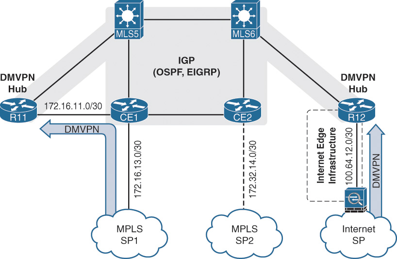
For organizations that are migrating from a dual MPLS topology to a hybrid topology (one MPLS transport and one Internet transport), only one DMVPN hub router needs to be connected to the MPLS and migration networks. The second DMVPN hub router connects to the Internet edge and the LAN. The interface terminating the DMVPN tunnel on the Internet is placed behind the Internet edge infrastructure that provides connectivity to the Internet.
Note
Notice that multilayer switches (MLSs) are being used instead of a traditional router. The use of an MLS in the WAN aggregation layer can reduce the number of cables needed between devices through the use of 802.1Q VLAN tags and subinterfaces. Using either a router or an MLS is acceptable for the design as long as the device is sized appropriately for the routing table and traffic rates. This is fairly common and is part of the WAN distribution layer.
The figures do not display the redundant link connecting R11 or CE1 with multilayer switch MLS6 or the equivalent redundant links between R12 and CE2. Redundancy should be used where it does not affect the design or flow of the traffic.
Example 16-1 provides a sample configuration of CE1 and CE2 for the dual MPLS environment that houses the DMVPN hub routers. The configuration allows CE1 and CE2 to make all outbound connectivity routing decisions within BGP. Notice that in the configuration:
![]() There is no mutual redistribution between OSPF and BGP.
There is no mutual redistribution between OSPF and BGP.
![]() BGP advertises the default route (originated by OSPF in the data center) toward the MPLS L3VPN PE routers.
BGP advertises the default route (originated by OSPF in the data center) toward the MPLS L3VPN PE routers.
![]() BGP advertises the new link between the CPE and DMVPN hub router.
BGP advertises the new link between the CPE and DMVPN hub router.
![]() The administrative distance (AD) for BGP is not modified. All the BGP routes are redistributed into OSPF.
The administrative distance (AD) for BGP is not modified. All the BGP routes are redistributed into OSPF.
![]() The AD for all OSPF routes from the other CE router is set higher than IBGP’s AD (200). The routes are matched on the OSPF router ID. This may affect any internal networks being advertised (loopback interfaces) in OSPF on the two CE routers, but the design is concerned with redistributed routes from the legacy WAN. This allows the BGP routing policy to influence outbound connectivity to the legacy network on both CE1 and CE2.
The AD for all OSPF routes from the other CE router is set higher than IBGP’s AD (200). The routes are matched on the OSPF router ID. This may affect any internal networks being advertised (loopback interfaces) in OSPF on the two CE routers, but the design is concerned with redistributed routes from the legacy WAN. This allows the BGP routing policy to influence outbound connectivity to the legacy network on both CE1 and CE2.
Example 16-1 CPE Configuration for Dual MPLS and Dual MPLS DMVPN
CE1
router ospf 1
router-id 10.1.0.33
redistribute bgp 100 subnets
network 0.0.0.0 255.255.255.255 area 0
distance 210 10.1.0.44 0.0.0.0
!
router bgp 100
bgp router-id 10.1.0.33
neighbor 10.1.34.14 remote-as 100
neighbor 10.1.34.14 description CE2
neighbor 172.16.13.2 remote-as 65000
neighbor 172.16.13.2 description SP1 Router
!
address-family ipv4
network 0.0.0.0
network 172.16.11.0 mask 255.255.255.252
network 172.16.13.0 mask 255.255.255.252
neighbor 10.1.34.14 activate
neighbor 172.16.13.2 activate
exit-address-family
CE2
router ospf 1
router-id 10.1.0.44
redistribute bgp 100 subnets
network 0.0.0.0 255.255.255.255 area 0
distance 210 10.1.0.33 0.0.0.0
!
router bgp 100
bgp router-id 10.1.0.14
neighbor 10.1.34.13 remote-as 100
neighbor 10.1.34.13 description CE1
neighbor 100.64.14.2 remote-as 60000
neighbor 100.64.14.2 description SP2 Router
!
address-family ipv4
network 0.0.0.0
network 100.64.12.0 mask 255.255.255.252
network 100.64.14.0 mask 255.255.255.252
neighbor 10.1.34.13 activate
neighbor 100.64.14.2 activate
exit-address-family
Figure 16-5 displays the low-level traffic patterns on an intermediate (IBlock) hub deployment for traffic flowing between the DMVPN network and the legacy WAN network. R41 transmits network traffic across the DMVPN network, which flows across the 172.16.13.0/30 and 172.16.11.0/30 networks in an encapsulated state. R11 decapsulates the packets and forwards the traffic out of its interface attached to the 10.1.110.0/24 network. MLS5 receives and forwards the packets on to CE1. CE1 then transmits the traffic (nonencapsulated) to the SP network where the traffic is forwarded on to R51.

Note
As part of the migration planning, it is important to understand the traffic flows between the IWAN DMVPN and legacy networks. Additional bandwidth could be consumed at the migration sites for network traffic flowing between a migrated branch site connecting to a nonmigrated branch site. If a heavy-volume branch site that is accessed by other branch sites is migrated first, all the sites in the legacy WAN will route through the migration network. This may saturate those network links. Deployment of QoS policies or acquisition of additional bandwidth (burst model) may be suggested depending on the duration of the migration.
The bandwidth concern does not apply to intra-DMVPN (spoke-to-spoke) network traffic, or to traffic between remote sites on the legacy network.
If IPsec protection with PKI authentication is to be used, the deployment of the CA and CRL should be done at this stage, so that routers can request certificates as part of the migration strategy.
Migrating the Branch Routers
Now that the DMVPN hub routers and PKI infrastructure (if required) have been deployed, the branch routers can be migrated onto the DMVPN network. The branch router’s configuration needs to have the DMVPN tunnel configuration, routing protocol changes, and PfR configuration deployed as part of the migration.
In Chapter 3, “Dynamic Multipoint VPN,” associating an FVRF to an interface was demonstrated, as well as the fact that the IP address was removed from that interface when the FVRF was associated. This causes a loss of connectivity during the change (the first stage of migration). Depending on the site’s connectivity model, the migration might be executed without loss of service to the users at the branch.
It is extremely critical to back up the existing router configuration to the local router and to a centralized repository. Any changes to authentication should be made to allow access to the router in a timely manner (assuming that TACACS or radius servers cannot be reached). Also, the routers should accept remote console sessions from the workstations on which the migration will be performed, and any peer routers. Basically, these steps prevent locking yourself out of the router, so that changes can be made to continue or back out of the migration.
Establishing a baseline of network services is vital for a successful migration. Generating a pre-migration and post-migration test plan should help with the verification of the migration. For example, if an application does not work after the migration, how can the network engineering team be assured that the problem was caused by the migration? Performing the test before the migration establishes a baseline, so network engineering can verify that the problem was migration related. If an application fails a connectivity test both before and after the migration, the problem is not caused by the migration.
The migration of branch routers is performed remotely or on site. The migration team needs to decide if resources will be required on site depending on the team’s comfort with the migration and the number of branch sites that have been previously migrated. Generally, migration of the first set of sites occurs with on-site resources, even if the remote procedure is used. This provides a method to overcome any automated techniques to keep the migration moving forward.
Migration of the branch routers involves the following simple steps:
![]() Creation and placement of the FVRF on the transport (WAN-facing) router interface.
Creation and placement of the FVRF on the transport (WAN-facing) router interface.
![]() Re-association of the IP address on the transport interface because it was removed upon FVRF association.
Re-association of the IP address on the transport interface because it was removed upon FVRF association.
![]() Configuration of DMVPN tunnel interfaces. The tunnels could be preconfigured, but connectivity cannot be established until the transport interface is placed in the FVRF.
Configuration of DMVPN tunnel interfaces. The tunnels could be preconfigured, but connectivity cannot be established until the transport interface is placed in the FVRF.
![]() Reconfiguration of routing protocols.
Reconfiguration of routing protocols.
![]() Verification of connectivity from remote networks to headquarters networks and vice versa.
Verification of connectivity from remote networks to headquarters networks and vice versa.
![]() Verification of PfR (if configured).
Verification of PfR (if configured).
Migration tasks can be performed from the command line or by using network management tools like APIC-EM or Prime Infrastructure that simplify many migration tasks.
Note
If the DMVPN tunnels will authenticate via PKI, the PKI trustpoints should be configured and the certificates requested and installed on the routers before the migration of the branch routers. The relevant PKI trustpoint information such as the VRF or enrollment URL can be changed after the initial certificate is deployed on the router.
Migrating a Single-Router Site with One Transport
Branch sites without redundancy will encounter packet loss during the migration. However, they can be converted remotely without the need for console access. The following steps outline the process:
Step 1. Preconfigure the DMVPN tunnel interface.
The DMVPN tunnel interface should be configured as explained in Chapter 3. If the DMVPN tunnel is encrypted, the encryption configuration should be applied too. There are no interfaces associated to the FVRF, and the tunnel will remain in a line protocol state of down.
Step 2. Configure the EEM applet on the router.
The Embedded Event Manager executes multiple commands to complete the configuration. Preconfiguring the EEM script allows the commands to be verified before implementation and allows review to detect any typos or mistakes before it executes. EEM scripts execute faster than a user can manually type in the commands and executes locally (even if an SSH session is disconnected from the FVRF association). The template script provided in Example 16-2 can be used. The essential components of the EEM script are
![]() Application of FVRF to the transport interface
Application of FVRF to the transport interface
![]() Re-application of the IP address to the transport address
Re-application of the IP address to the transport address
![]() Application of routing protocols
Application of routing protocols
Depending upon the transport, additional tasks may need to be performed. For example, if the transport interface is a point-to-point IPsec tunnel, the crypto map may need to be removed from that interface in the EEM script.
Example 16-2 EEM Applet for Migration
Branch Router To Be Migrated
event manager applet MIGRATE
event none
action 010 cli command "enable"
action 020 cli command "configure terminal"
! This section enables the MPLS FVRF and No Shuts the MPLS Tunnel
action 030 cli command "interface GigabitEthernet0/1"
action 040 cli command "vrf forwarding MPLS01"
action 050 cli command "ip address 172.16.31.1 255.255.255.252"
action 060 cli command "ip route vrf MPLS01 0.0.0.0 0.0.0.0 Giga0/1 172.16.31.2"
action 070 cli command "interface Tunnel 100"
action 080 cli command "no shut"
! This section enables the Internet FVRF and No Shuts the Internet Tunnel
action 090 cli command "interface GigabitEthernet0/2"
action 100 cli command "vrf forwarding INET01"
action 110 cli command "ip address dhcp"
! The wait command allows the interface to obtain an IP address from DHCP
! before the Internet DMVPN tunnel is brought online
action 120 wait 15
action 130 cli command "interface Tunnel 200"
action 140 cli command "no shut"
action 150 syslog msg "Interface Configurations Performed "
! The last section is to remove the previous routing protocol configuration
! and then configure the routing protocols. Only a portion of this activity
! is shown, but this section should be completed based on your design.
action 160 cli command "no router bgp 65000"
action 170 cli command "no router ospf 1"
action 180 cli command "router eigrp IWAN"
! Continue with rest of routing protocol configuration
action 999 syslog msg "Migration Complete"
Note
The EEM script action numbering is sorted alphanumerically. For example, if there are three actions, 1, 2, and 11, EEM places them in the following order: 1, 11, and 2. Keeping all the number lengths consistent means the order will be consistent with numeric sorting.
Step 3. Save the current configuration.
The router’s configuration needs to be saved to nonvolatile memory with the command copy running-config startup-config.
Step 4. Configure the router to reload in 15 minutes.
In the event the DMVPN tunnel does not establish, the router should be reloaded to restore connectivity. The executive command reload in 15 will count down to 15 minutes and initiate a reload of the router.
This step can be skipped if the migration is being performed locally at the branch site.
Step 5. Execute the EEM script.
The EEM script is executed with the command event applet run applet-name.
Step 6. Restore connectivity to the router.
Connectivity to the router will be lost if connected remotely. Connect back to the router using the tunnel IP address or the interface associated to the FVRF.
Step 7. Cancel the router reload.
Cancel the router reload with the command reload cancel.
Step 8. Complete the migration.
Once verification of all routing patterns and connectivity is completed, save the router’s configuration and reenable any authentication or security policies that were changed for the migration.
Note
Branch sites that contain backdoor network links should be migrated at the same time and considered as a dual-router IWAN site for the steps of migration. For example, a remote site has a high-speed MPLS VPN connection as a primary connection. It also maintains a backup dedicated T1 to another nearby branch that also uses a high-speed MPLS VPN connection as a primary connection. These two sites should be migrated during the same migration window.
Migrating a Single-Router Site with Multiple Transports
Branch sites that have a single router with multiple transports will encounter a small period of packet loss during the migration. The following steps outline the process:
Step 1. Establish connectivity.
Connect to the router via its loopback IP address.
Step 2. Save the current configuration.
The router’s configuration needs to be saved to nonvolatile memory with the command copy running-config startup-config.
Step 3. Configure the router to reload in 15 minutes.
In the event that the migration causes a loss of connectivity, the router should be reloaded to restore connectivity. The executive command reload in 15 counts down to 15 minutes and initiates a reload of the router.
Step 4. Configure the FVRF.
Create the FVRF on the router, and associate the FVRF to the secondary transport interface. Reapply the original IP address to the secondary transport interface.
If connectivity is lost, reestablish connectivity to the loopback interface.
Step 5. Configure the DMVPN tunnel for the secondary transport.
Configure the DMPVPN tunnel and crypto map and establish connectivity to the DMVPN hub router for the secondary transport.
Step 6. Configure a static default route.
Configure a static default route to provide connectivity to your workstation via the DMVPN cloud while the routing protocols are modified.
Step 7. Modify the dynamic routing protocol configuration.
Modify the routing protocol configuration so that the protocol peers with the DMVPN hub routers to exchange routes.
If connectivity is lost, reestablish connectivity to the DMVPN tunnel IP address.
Note
If the BGP autonomous system number is changed, the BGP configuration must be completely removed. During this time, any routes advertised to the central site are rescinded and connectivity is lost until BGP can be reconfigured.
Step 8. Configure the primary transport interface and DMVPN tunnel.
Now that routing has established on the secondary DMVPN tunnel, the FVRF can be associated to the primary transport.
Step 9. Configure the DMVPN tunnel.
Configure the DMPVPN tunnel and crypto map and establish connectivity to the DMVPN hub router.
Step 10. Modify the dynamic routing protocol configuration.
Modify the routing protocol configuration so that the protocol peers with the DMVPN hub routers to exchange routes.
Step 11. Cancel the router reload.
Cancel the router reload with the command reload cancel.
Step 12. Complete the migration.
The last tasks need to be completed after the second transport has been migrated and connectivity from both DMVPN tunnels has been verified. The static default route from Step 6 needs to be backed out, the router’s configuration saved, and authentication or security policies that were changed for the migration reenabled.
Migrating a Dual-Router Site with Multiple Transports
Sites that contain multiple routers with multiple transports can be migrated without any packet loss. The migration process can be executed with the following steps:
Step 1. Establish connectivity.
Connect to the router that is not being migrated in the branch site. This router acts as a jump box during the configuration of the first router. From this router an SSH session needs to be established to the router that is being migrated.
Step 2. Save the current configuration.
The router’s configuration is saved to nonvolatile memory with the command copy running-config startup-config.
Step 3. Configure the router to reload in 15 minutes.
In the event that the migration causes a loss of connectivity, the router should be reloaded to restore connectivity. The executive command reload in 15 counts down to 15 minutes and initiates a reload of the router.
Step 4. Disable the secondary transport interface.
Shut down the secondary transport interface. This terminates any routing protocol neighborships with the other routers and remove any routes learned from those neighborships.
Step 5. Configure the routing protocols.
Remove the routing protocol configuration and place the routing protocol configuration for the DMVPN topology.
Note
Additional configuration may be needed to filter routes that are redistributed or advertised out toward the DMVPN network. It is important that routes learned from the active peer router (legacy WAN) not be advertised into the DMVPN network. This is done to prevent the site that is being migrated from being a transit site that could cause connectivity issues.
Step 6. Configure the transport interface and DMVPN tunnel.
Associate the FVRF to the transport interface, create the crypto map, create the DMVPN tunnel interface, and establish connectivity to the DMVPN cloud.
Step 7. Cancel the router reload.
Cancel the router reload with the command reload cancel.
Step 8. Configure the other router.
After the DMVPN tunnel has established and connectivity is verified across the DMVPN tunnel, repeat Steps 1 through 7 for the other router.
Step 9. Complete the migration.
The final tasks need to be completed after the second router has been migrated and connectivity from both DMVPN tunnels has been verified. Authentication and security policies should be reenabled and the router’s configuration should be saved.
Post-Migration Tasks
Depending on the size of the environment, the migration may take days, weeks, or months. After all the branch routers have been completely migrated and the SP network is used only for transport between DMVPN routers, the migration has been completed. The last task is to clean up the environment.
Figure 16-6 illustrates the various stages of the DMVPN hub IBlock deployment at various stages. MLS5 is one of the WAN distribution switches, R11 is the DMVPN hub router, and CE1 is the customer edge router that connects to the SP network. The 10.1.133.0/30 link between the WAN distribution switch (MLS5) and CE1 router is no longer needed and can be removed. R11’s GigabitEthernet0/1 interface on the 172.16.11.0/30 network belongs to the FVRF for that transport, and the GigabitEthernet0/3 interface on the 10.1.110.0/24 network faces the WAN distribution block.

Note
If the final design does not require migrating all the sites, these steps should not be performed because they will remove connectivity between the IWAN and legacy WAN.
The second illustration in Figure 16-6 shows the topology with the 10.1.133.0/24 link removed. Removing the link has no impact because traffic should not be flowing between R10 and any other branch sites on the legacy WAN.
CE1 can be removed depending on the following factors:
![]() Who owns the device: your organization or the SP?
Who owns the device: your organization or the SP?
![]() What additional value does the device add to the design or operational perspective?
What additional value does the device add to the design or operational perspective?
If deemed unnecessary, the device can be removed with one major caveat. How is connectivity established between the SP network and R11? If the cable on CE1 that connects to the MPLS L3VPN PE is moved directly to R11, R11 connectivity will break. R11’s IP address is on the 172.16.11.0/30 network and the SP’s PE router is on the 172.16.13.0/30 network. One of the devices will have to have a different IP address.
Changing R11’s IP address from 172.16.11.1 to 172.16.13.1 maintains connectivity to the transport network, but unfortunately all the branch routers are configured to use the 172.16.11.1 IP address for their NBMA address of the DMVPN tunnel.
There are three solutions to this issue:
1. Configure a loopback interface on the hub router. Place the loopback into the FVRF and terminate the DMVPN sessions on the loopback interface. The loopback interface must be advertised and reachable in the transport network. Be aware of potential QoS problems with ECMP if there are multiple links in the FVRF to reach the SP network.
2. Coordinate the change with your SP. When the cable is moved from CE1 to R11, have the SP change the IP address on the PE router. Branch sites will still have connectivity to the other DMVPN hub for that tunnel. A change window should be identified in advance. All four hubs (two per transport and two transports) can be migrated over multiple maintenance windows.
3. Reconfigure the NHRP mappings on every branch site. During the time of reconfiguration, the spoke loses connectivity to one of the two hubs for that DMVPN cloud. This technique requires every branch site to be changed twice and is not very effective.
The first and second options provide the most straightforward approaches when removing a CE device. If there is a potential of the CE router being removed, change the design so that the DMVPN tunnel terminates on the hub router’s loopback before any branch sites have been migrated. If branch sites have already been deployed, it may be easier just to perform the second option.
Note
The CE1 router can be left in place. In essence, it has become a part of the transport network.
Migrating from a Dual MPLS to a Hybrid IWAN Model
The process for migrating from a legacy environment that uses two different MPLS SPs to a hybrid IWAN model is straightforward. A DMVPN hub router is deployed for the MPLS transport, and a DVMPN hub router is deployed for the Internet transport. Nothing needs to be done with the transport of the second MPLS SP. Figure 16-7 displays R11 (DMVPN hub for MPLS) connected to CE1 via the IBlock method to communicate with MPLS SP1, and R12 is connected directly to the Internet edge.
The branch site migration consists of
![]() Ordering the new Internet circuits at the branch sites
Ordering the new Internet circuits at the branch sites
![]() Configuring the MPLS SP1 and Internet FVRFs
Configuring the MPLS SP1 and Internet FVRFs
![]() Configuring the transport interfaces: MPLS SP1 and Internet
Configuring the transport interfaces: MPLS SP1 and Internet
![]() Configuring the DMVPN tunnels
Configuring the DMVPN tunnels
![]() Configuring the routing protocols
Configuring the routing protocols
![]() Removing the configuration for MPLS SP2 on the branch routers and canceling the circuit
Removing the configuration for MPLS SP2 on the branch routers and canceling the circuit
The CE2 router remains in place until all branch sites have been migrated off of the legacy network. CE1 and CE2 are used to provide connectivity between the legacy sites with the data centers or IWAN branch sites. Once the migrations have been completed, the link between CE1 and R11 can process and the removal of CE2 and the data centers can occur.
Whether or not the CE1 router is maintained for the MPLS DMVPN hub is dependent upon the same variables as described in the previous section. Figure 16-8 displays the DMVPN hub topology at the data center after the migration is completed.

Migrating IPsec Tunnels
IPsec tunnels are a point-to-point technology. The migration process for IPsec tunnels involves the establishment of the DMVPN hub into the network. Figure 16-9 illustrates the migration process. In the initial IPsec topology:
![]() A point-to-point tunnel (192.168.13.0/30) exists between R1 and R3.
A point-to-point tunnel (192.168.13.0/30) exists between R1 and R3.
![]() A point-to-point tunnel (192.168.14.0/30) exists between R1 and R4.
A point-to-point tunnel (192.168.14.0/30) exists between R1 and R4.
![]() A point-to-point tunnel (192.168.45.0/30) exists between R4 and R5.
A point-to-point tunnel (192.168.45.0/30) exists between R4 and R5.

Step 1. Deploy the DMVPN hub router.
R2, the DMVPN hub router, is deployed and connected directly to R1. Traffic between the point-to-point topology and the DMVPN network should traverse R1 and R2.
Step 2. Migrate non-transit sites first.
R5 is identified as the first router to be migrated because it is not being used as a transit router. R5 is migrated using the steps in the section “Migrating the Branch Routers.”
Step 3. Shut down the unnecessary point-to-point link.
The point-to-point tunnel between R4 and R5 is shut down to prevent transit routing or routing loops.
R4 is identified as the next router to be migrated. R4 is migrated using the steps listed in the section “Migrating the Branch Routers.”
Step 5. Shut down the unnecessary point-to-point link.
The point-to-point tunnel between R1 and R4 is shut down to prevent transit routing or routing loops.
Step 6. Continue the migration.
Steps 4 and 5 are repeated as needed for other routers until all the point-to-point tunnels are migrated.
The process for migrating an IPsec environment to DMVPN is based upon the concept that routers are terminating the IPsec connection. If the devices terminating the IPsec session are firewalls, the DMVPN routers need to be placed behind the firewalls. Traffic from the DMVPN routers needs to pass through the firewalls onto the transport network and not across the firewall’s IPsec tunnels.
PfR Deployment
The PfR domain policy should be configured when the DMVPN hub routers are deployed. PfR is a relatively new technology that may take time to learn. Initial PfR policies should start with limited functions and increase over time as users become accustomed to working with the tool. As more and more sites migrate onto IWAN, and the network engineering team understands PfR better, additional logic can be added to the PfR domain policy.
In Chapter 8, “PfR Provisioning,” the concepts of PfR site prefixes and PfR enterprise prefixes were introduced. They are essential components of the operation of PfR. The enterprise prefix list is configured on the Hub MC and defines the enterprise prefixes that PfR should control more granularly. Network traffic outside of the enterprise prefix list is considered a PfR Internet prefix which cannot check path characteristics such as latency or jitter. Only when both source and destination networks reside in the enterprise prefix list can path characteristics such as latency and jitter be monitored.
For example, if the enterprise prefix list includes only the 10.0.0.0/8 network range, traffic between 192.168.11.0/24 and 192.168.22.0/24 does not check a path’s delay even if the network traffic matches the QoS EF DSCP that is defined in the policy that PfR should check for delayed EF DSCP traffic.
PfR includes the concept of a PfR site prefix that is a database containing the inside prefixes for every site. The PfR site prefix database is built from the egress performance monitor and is advertised to the Hub MC dynamically (branches only) or can be statically configured.
This section explains the internal PfR components during migration. Figure 16-10 displays a simple topology (assume that Site 2 does not exist), and Site 1 is the migration site (R11 and R12 are the only DMVPN hub routers). R31 and R41 are continuously communicating with each other with traffic that matches the appropriate PfR policy that monitors a path’s delay.

Example 16-3 displays the PfR configuration on R10. Notice that the enterprise prefix list contains the 10.0.0.0/8 network prefix and the 10.1.0.0/16 site prefix is programmed on R10.
Example 16-3 R10’s Initial PfR Configuration
R10 (Hub MC)
domain IWAN
vrf default
master hub
enterprise-prefix prefix-list ENTERPRISE_PREFIX
site-prefixes prefix-list SITE_PREFIX
!
ip prefix-list ENTERPRISE_PREFIX seq 10 permit 10.0.0.0/8
ip prefix-list SITE_PREFIX seq 10 permit 10.1.0.0/16
At this time, R31 and R41 reside on the legacy networks. They are able to communicate directly with each other using the legacy SP transport network. Example 16-4 displays the PfR site prefix database which has only the static 10.1.0.0/16 network that was defined on R10. Notice that 10.0.0.0/8 site prefix is associated to all site IDs with the value of 255.255.255.255.
Example 16-4 PfR Site Prefix Database—Initial Hubs
R10-HUB-MC# show domain IWAN master site-prefix
Prefix DB Origin: 10.1.0.10
Prefix Flag: S-From SAF; L-Learned; T-Top Level; C-Configured; M-shared
Site-id Site-prefix Last Updated DC Bitmap Flag
--------------------------------------------------------------------------------
10.1.0.10 10.1.0.10/32 00:13:41 ago 0x1 L
10.1.0.10 10.1.0.0/16 00:13:41 ago 0x1 C,M
255.255.255.255 *10.0.0.0/8 00:13:41 ago 0x1 T
R31 has been migrated to the IWAN architecture as shown in Figure 16-11. Traffic between R31 and the rest of the network is on the IWAN network until it reaches the migration site. Traffic may terminate locally in Site 1 or be forwarded on to R41 which resides on the legacy WAN.

Example 16-5 displays the Site 3 prefixes (10.3.3.0/24 and 10.3.0.31/32) that have been dynamically discovered and reported to R10. Notice that the Site 4 prefix (10.4.4.0/24) has not been added even though traffic still flows between both sites. Remember that site prefixes must be statically defined on any hub or transit MCs. In the current state, PfR manages (verifies that the path’s delay is within policy) network traffic between R31 (10.3.0.0/16) and Site 1 (10.1.0.0/16) and networks.
However, network traffic from R31 to R41 is not managed by PfR because Site 4’s site prefixes have not been discovered in the PfR domain. Although the 10.4.0.0/16 network range may reside inside the 10.0.0.0/8 range displayed in Example 16-5, the 10.0.0.0/8 is not associated to a specific site. The site ID of 255.255.255.255 indicates that this entry is defined only in the enterprise prefix list. Traffic is not controlled by PfR because the source and destination have not been completely identified. PfR can only load-balance (if configured) the network traffic; it cannot monitor delay, jitter, or packet loss. In essence, R31 uses the routing table to reach the DMVPN hub routers, and then CE1 uses the routing table to reach R41.
Example 16-5 R31 Is Migrated to IWAN While R41 Is on the Legacy WAN
R10-HUB-MC# show domain IWAN master site-prefix
Prefix DB Origin: 10.1.0.10
Prefix Flag: S-From SAF; L-Learned; T-Top Level; C-Configured; M-shared
Site-id Site-prefix Last Updated DC Bitmap Flag
--------------------------------------------------------------------------------
10.1.0.10 10.1.0.10/32 00:20:51 ago 0x1 L
10.1.0.10 10.1.0.0/16 00:20:51 ago 0x1 C,M
10.3.0.31 10.3.0.31/32 00:01:19 ago 0x0 S
10.3.0.31 10.3.3.0/24 00:01:19 ago 0x0 S
255.255.255.255 *10.0.0.0/8 00:20:51 ago 0x1 T
It is possible to have PfR manage half of the path between the migrated branch site and legacy sites because all the traffic must flow through the DMVPN hubs located at Site 1. The 10.0.0.0/8 prefix can be added to Site 1’s site prefix list and allows PfR to monitor the path between migrated sites and the DMVPN hubs.
Note
The exact prefix added to the site prefix list should be advertised from the DMVPN hub for PfR to have a parent route. In essence, this is the enterprise summary route that was defined in Chapter 4 for the topology.
Example 16-6 demonstrates the addition of the 10.0.0.0/8 prefix to Site 1’s prefix list.
Example 16-6 R10’s PfR Configuration with Enhanced Site Prefix List
R10 (Hub MC)
domain IWAN
vrf default
master hub
enterprise-prefix prefix-list ENTERPRISE_PREFIX
site-prefixes prefix-list SITE_PREFIX
!
ip prefix-list ENTERPRISE_PREFIX seq 10 permit 10.0.0.0/8
ip prefix-list SITE_PREFIX seq 10 permit 10.1.0.0/16
ip prefix-list SITE_PREFIX seq 20 permit 10.0.0.0/8
Figure 16-12 displays that R31 is now able to monitor path attributes such as delay, jitter, and packet loss between it and the DMVPN hub routers. After traffic reaches the DMVPN hub routers, they use the routing table to reach the legacy CE routers, which then forward the traffic on to the legacy WAN.

Example 16-7 displays the site prefixes after the change is made. Notice that the 10.0.0.0/8 prefix is associated to Site 1 (10.1.0.10). PfR now monitors the path between R31 and R41 for delay in both directions between R31 and the DMVPN hub routers.
Example 16-7 Added Site Prefix 10.0.0.0/8 on Hub MC (Transit Site)
R10-HUB-MC# show domain IWAN master site-prefix
Prefix DB Origin: 10.1.0.10
Prefix Flag: S-From SAF; L-Learned; T-Top Level; C-Configured; M-shared
Site-id Site-prefix Last Updated DC Bitmap Flag
--------------------------------------------------------------------------------
10.1.0.10 10.1.0.10/32 00:39:39 ago 0x1 L
10.1.0.10 10.1.0.0/16 00:39:39 ago 0x1 C,M
10.3.0.31 10.3.0.31/32 00:02:46 ago 0x0 S
10.3.0.31 10.3.0.0/16 00:02:46 ago 0x0 S
10.1.0.10 *10.0.0.0/8 00:00:05 ago 0x1 T,C,M
Figure 16-13 displays that R41 has been migrated onto the IWAN architecture. Communication between R31 and R41 can occur directly after the spoke-to-spoke DMVPN tunnel is established. R31 is now able to monitor path attributes such as delay, jitter, and packet loss between it and R41.

The 10.4.4.0/24 and 10.4.0.41/32 site prefixes have been dynamically added to the site prefix list as shown in Example 16-8. Just like what happened with the routing table, PfR uses the most explicit match for identifying a network to a site ID. PfR can now monitor the end-to-end path between R31 and R41.
Note
Now that both R31 and R41 have been migrated to the IWAN architecture, a spoke-to-spoke tunnel has formed, providing direct connectivity between the two.
Example 16-8 Site Prefix List After R41’s Migration
R10-HUB-MC# show domain IWAN master site-prefix
Prefix DB Origin: 10.1.0.10
Prefix Flag: S-From SAF; L-Learned; T-Top Level; C-Configured; M-shared
Site-id Site-prefix Last Updated DC Bitmap Flag
--------------------------------------------------------------------------------
10.1.0.10 10.1.0.10/32 00:56:20 ago 0x1 L
10.1.0.10 10.1.0.0/16 00:56:20 ago 0x1 C,M
10.3.0.31 10.3.0.31/32 00:19:27 ago 0x0 S
10.3.0.31 10.3.0.0/16 00:19:27 ago 0x0 S
10.4.0.41 10.4.0.41/32 00:06:09 ago 0x0 S
10.4.0.41 10.4.4.0/24 00:06:09 ago 0x0 S
10.1.0.10 *10.0.0.0/8 00:16:46 ago 0x1 T,C,M
Note
Adding the entire enterprise prefix list to the migration site’s prefix list allows PfR to monitor a portion of the path between the IWAN architecture and the legacy network. PfR cannot manage true end-to-end latency. This step is optional and does not have to be configured, but most customers find it beneficial.
Testing the Migration Plan
Any successful deployment of a new technology includes a solid design with a detailed migration plan. Testing the migration plan in advance of the actual implementation provides an opportunity to identify overlooked details that could cause issues.
Initial testing can be performed on Cisco VIRL (Virtual Internet Routing Lab) which provides a scalable, extensible network design and simulation environment. VIRL has been used by many customers for a variety of testing prior to deployment in a production network. It includes several Cisco Network Operating System virtual machines (IOSv, IOS XRv, CSR1000v, NX-OSv, IOSvL2, and ASAv) and has the ability to integrate with third-party-vendor virtual machines. It includes many unique capabilities such as “live visualization” that provide the ability to create protocol diagrams in real time from a running simulation. More information about VIRL can be found at http://virl.cisco.com.
Summary
This chapter covered the processes needed to successfully migrate an existing WAN to Cisco IWAN. A successful migration includes the following:
![]() Documenting the existing network
Documenting the existing network
![]() Finalizing the design
Finalizing the design
![]() Deploying a proof of concept or production pilot of the network
Deploying a proof of concept or production pilot of the network
![]() Creating a high-level migration plan
Creating a high-level migration plan
![]() Testing the execution plans in a lab environment and modifying the plan accordingly
Testing the execution plans in a lab environment and modifying the plan accordingly
![]() Deploying DMVPN hub routers
Deploying DMVPN hub routers
![]() Deploying PKI infrastructure (if necessary)
Deploying PKI infrastructure (if necessary)
![]() Post-migration cleanup tasks
Post-migration cleanup tasks
This chapter provided a high-level overview of the tasks to deploy the transport independence and intelligent path control components of the IWAN architecture. Testing the high-level and low-level execution plan is vital and allows the plans to be modified if necessary. Application optimizations and direct Internet access can be deployed before, after, or during the deployment of transport independence.
Reach out to the local Cisco partners or account team with any other questions you may have about migrations.
Further Reading
Cisco. “Cisco IOS Software Configuration Guides.” www.cisco.com.
Edgeworth, Brad, and Mani Ganesan. “Migrating Your Existing WAN to Cisco’s IWAN.” Presented at Cisco Live, Berlin, 2016.