
Chapter 3. Dynamic Multipoint VPN
This chapter covers the following topics:
![]() Generic routing encapsulation (GRE) tunnels
Generic routing encapsulation (GRE) tunnels
![]() Next Hop Resolution Protocol (NHRP)
Next Hop Resolution Protocol (NHRP)
![]() Dynamic Multipoint VPN (DMVPN) tunnels
Dynamic Multipoint VPN (DMVPN) tunnels
![]() DMVPN failure and detection and high availability
DMVPN failure and detection and high availability
![]() DMVPN dual-hub and dual-cloud designs
DMVPN dual-hub and dual-cloud designs
![]() Sample IWAN DMVPN transport models
Sample IWAN DMVPN transport models
Dynamic Multipoint VPN (DMVPN) is a Cisco solution that provides a scalable VPN architecture. DMVPN uses generic routing encapsulation (GRE) for tunneling, Next Hop Resolution Protocol (NHRP) for on-demand forwarding and mapping information, and IPsec to provide a secure overlay network to address the deficiencies of site-to-site VPN tunnels while providing full-mesh connectivity. This chapter explains the underlying technologies and components of deploying DMVPN for IWAN.
DMVPN provides the following benefits to network administrators:
![]() Zero-touch provisioning: DMVPN hubs do not require additional configuration when additional spokes are added. DMVPN spokes can use a templated tunnel configuration.
Zero-touch provisioning: DMVPN hubs do not require additional configuration when additional spokes are added. DMVPN spokes can use a templated tunnel configuration.
![]() Scalable deployment: Minimal peering and minimal permanent state on spoke routers allow for massive scale. Network scale is not limited by device (physical, virtual, or logical).
Scalable deployment: Minimal peering and minimal permanent state on spoke routers allow for massive scale. Network scale is not limited by device (physical, virtual, or logical).
![]() Spoke-to-spoke tunnels: DMVPN provides full-mesh connectivity while configuring only the initial spoke-to-hub tunnel. Dynamic spoke-to-spoke tunnels are created as needed and torn down when no longer needed. There is no packet loss while building dynamic on-demand spoke-to-spoke tunnels after the initial spoke-to-hub tunnels are established. A spoke maintains forwarding states only for spokes with which it is communicating.
Spoke-to-spoke tunnels: DMVPN provides full-mesh connectivity while configuring only the initial spoke-to-hub tunnel. Dynamic spoke-to-spoke tunnels are created as needed and torn down when no longer needed. There is no packet loss while building dynamic on-demand spoke-to-spoke tunnels after the initial spoke-to-hub tunnels are established. A spoke maintains forwarding states only for spokes with which it is communicating.
![]() Flexible network topologies: DMVPN operation does not make any rigid assumptions about either the control plane or data plane overlay topologies. The DMVPN control plane can be used in a highly distributed and resilient model that allows massive scale and avoids a single point of failure or congestion. At the other extreme, it can also be used in a centralized model for a single point of control.
Flexible network topologies: DMVPN operation does not make any rigid assumptions about either the control plane or data plane overlay topologies. The DMVPN control plane can be used in a highly distributed and resilient model that allows massive scale and avoids a single point of failure or congestion. At the other extreme, it can also be used in a centralized model for a single point of control.
![]() Multiprotocol support: DMVPN supports IPv4, IPv6, and MPLS as the overlay or transport network protocol.
Multiprotocol support: DMVPN supports IPv4, IPv6, and MPLS as the overlay or transport network protocol.
![]() Multicast support: DMVPN allows multicast traffic to flow on the tunnel interfaces.
Multicast support: DMVPN allows multicast traffic to flow on the tunnel interfaces.
![]() Adaptable connectivity: DMVPN routers can establish connectivity behind Network Address Translation (NAT). Spoke routers can use dynamic IP addressing such as Dynamic Host Configuration Protocol (DHCP).
Adaptable connectivity: DMVPN routers can establish connectivity behind Network Address Translation (NAT). Spoke routers can use dynamic IP addressing such as Dynamic Host Configuration Protocol (DHCP).
![]() Standardized building blocks: DMVPN uses industry-standardized technologies (NHRP, GRE, and IPsec) to build an overlay network. This propagates familiarity while minimizing the learning curve and easing troubleshooting.
Standardized building blocks: DMVPN uses industry-standardized technologies (NHRP, GRE, and IPsec) to build an overlay network. This propagates familiarity while minimizing the learning curve and easing troubleshooting.
Generic Routing Encapsulation (GRE) Tunnels
A GRE tunnel provides connectivity to a wide variety of network-layer protocols by encapsulating and forwarding those packets over an IP-based network. The original use of GRE tunnels was to provide a transport mechanism for nonroutable legacy protocols such as DECnet, Systems Network Architecture (SNA), or IPX. GRE tunnels have been used as a quick workaround for bad routing designs, or as a method to pass traffic through a firewall or ACL. DMVPN uses multipoint GRE (mGRE) encapsulation and supports dynamic routing protocols, which eliminates many of the support issues associated with other VPN technologies. GRE tunnels are classified as an overlay network because the GRE tunnel is built on top of an existing transport network, also known as an underlay network.
Additional header information is added to the packet when the router encapsulates the packet for the GRE tunnel. The new header information contains the remote endpoint IP address as the destination. The new IP headers allow the packet to be routed between the two tunnel endpoints without inspection of the packet’s payload. After the packet reaches the remote endpoint, the GRE headers are removed, and the original packet is forwarded out of the remote router.
The following section explains the fundamentals of a GRE tunnel before explaining multipoint GRE tunnels that are a component of DMVPN. The process for configuring a GRE tunnel is described in the following sections.
GRE Tunnel Configuration
Figure 3-1 illustrates the configuration of a GRE tunnel. The 172.16.0.0/16 network range is the transport (underlay) network, and 192.168.100.0/24 is used for the GRE tunnel (overlay network).
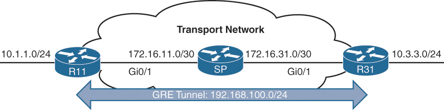
In this topology, R11, R31, and the SP router have enabled Routing Information Protocol (RIP) on all the 10.0.0.0/8 and 172.16.0.0/16 network interfaces. This allows R11 and R31 to locate the remote router’s encapsulating interface. R11 uses the SP router as a next hop to reach the 172.16.31.0/30 network, and R31 uses the SP router as a next hop toward the 172.16.11.0/30 network.
Note
The RIP configuration does not include the 192.168.0.0/16 network range.
Example 3-1 shows the routing table of R11 before the GRE tunnel is created. Notice that the 10.3.3.0/24 network is reachable by RIP and is two hops away.
Example 3-1 R11 Routing Table Without the GRE Tunnel
R11# show ip route
! Output omitted for brevity
Codes: L - local, C - connected, S - static, R - RIP, M - mobile, B - BGP
D - EIGRP, EX - EIGRP external, O - OSPF, IA - OSPF inter area
Gateway of last resort is not set
10.0.0.0/8 is variably subnetted, 3 subnets, 2 masks
C 10.1.1.0/24 is directly connected, GigabitEthernet0/2
R 10.3.3.0/24 [120/2] via 172.16.11.2, 00:00:01, GigabitEthernet0/1
172.16.0.0/16 is variably subnetted, 3 subnets, 2 masks
C 172.16.11.0/30 is directly connected, GigabitEthernet0/1
R 172.16.31.0/30 [120/1] via 172.16.11.2, 00:00:10, GigabitEthernet0/1
R11# trace 10.3.3.3 source 10.1.1.1
Tracing the route to 10.3.3.3
1 172.16.11.2 0 msec 0 msec 1 msec
2 172.16.31.3 0 msec
The steps for configuring GRE tunnels are as follows:
Step 1. Create the tunnel interface.
Create the tunnel interface with the global configuration command interface tunnel tunnel-number.
Step 2. Identify the tunnel source.
Identify the local source of the tunnel with the interface parameter command tunnel source {ip-address | interface-id}. The tunnel source interface indicates the interface that will be used for encapsulation and decapsulation of the GRE tunnel. The tunnel source can be a physical interface or a loopback interface. A loopback interface can provide reachability if one of the transport interfaces were to fail.
Step 3. Identify the remote destination IP address.
Identify the tunnel destination with the interface parameter command tunnel destination ip-address. The tunnel destination is the remote router’s underlay IP address toward which the local router sends GRE packets.
Step 4. Allocate an IP address to the tunnel interface.
An IP address is allocated to the interface with the command ip address ip-address subnet-mask.
Step 5. Define the tunnel bandwidth (optional).
Virtual interfaces do not have the concept of latency and need to have a reference bandwidth configured so that routing protocols that use bandwidth for best-path calculation can make an intelligent decision. Bandwidth is also used for QoS configuration on the interface. Bandwidth is defined with the interface parameter command bandwidth [1-10000000], which is measured in kilobits per second.
Step 6. Specify a GRE tunnel keepalive (optional).
Tunnel interfaces are GRE point-to-point (P2P) by default, and the line protocol enters an up state when the router detects that a route to the tunnel destination exists in the routing table. If the tunnel destination is not in the routing table, the tunnel interface (line protocol) enters a down state.
Tunnel keepalives ensure that bidirectional communication exists between tunnel endpoints to keep the line protocol up. Otherwise the router must rely upon routing protocol timers to detect a dead remote endpoint.
Keepalives are configured with the interface parameter command keepalive [seconds [retries]]. The default timer is 10 seconds and three retries.
Step 7. Define the IP maximum transmission unit (MTU) for the tunnel interface (optional).
The GRE tunnel adds a minimum of 24 bytes to the packet size to accommodate the headers that are added to the packet. Specifying the IP MTU on the tunnel interface has the router perform the fragmentation in advance of the host having to detect and specify the packet MTU. IP MTU is configured with the interface parameter command ip mtu mtu.
Table 3-1 displays the amount of encapsulation overhead for various tunnel techniques. The header size may change based upon the configuration options used. For all of our examples, the IP MTU is set to 1400.

GRE Example Configuration
Example 3-2 provides the GRE tunnel configuration for R11 and R31. EIGRP is enabled on the LAN (10.0.0.0/8) and GRE tunnel (192.168.100.0/24) networks. RIP is enabled on the LAN (10.0.0.0/8) and transport (172.16.0.0/16) networks but is not enabled on the GRE tunnel. R11 and R31 become direct EIGRP peers on the GRE tunnel because all the network traffic is encapsulated between them.
EIGRP has a lower administrative distance (AD), 90, and the routers use the route learned via the EIGRP connection (using the GRE tunnel) versus the route learned via RIP (120) that came from the transport network. Notice that the EIGRP configuration uses named mode. EIGRP named mode provides clarity and keeps the entire EIGRP configuration in one centralized location. EIGRP named mode is the only method of EIGRP configuration that supports some of the newer features such as stub site.
R11
interface Tunnel100
bandwidth 4000
ip address 192.168.100.11 255.255.255.0
ip mtu 1400
keepalive 5 3
tunnel source GigabitEthernet0/1
tunnel destination 172.16.31.1
!
router eigrp GRE-OVERLAY
address-family ipv4 unicast autonomous-system 100
topology base
exit-af-topology
network 10.0.0.0
network 192.168.100.0
exit-address-family
!
router rip
version 2
network 172.16.0.0
no auto-summary
R31
interface Tunnel100
bandwidth 4000
ip address 192.168.100.31 255.255.255.0
ip mtu 1400
keepalive 5 3
tunnel source GigabitEthernet0/1
tunnel destination 172.16.11.1
!
router eigrp GRE-OVERLAY
address-family ipv4 unicast autonomous-system 100
topology base
exit-af-topology
network 10.0.0.0
network 192.168.100.0
exit-address-family
!
router rip
version 2
network 172.16.0.0
no auto-summary
Now that the GRE tunnel is configured, the state of the tunnel can be verified with the command show interface tunnel number. Example 3-3 displays output from the command. Notice that the output includes the tunnel source and destination addresses, keepalive values (if any), and the tunnel line protocol state, and that the tunnel is a GRE/IP tunnel.
Example 3-3 Display of GRE Tunnel Parameters
R11# show interface tunnel 100
! Output omitted for brevity
Tunnel100 is up, line protocol is up
Hardware is Tunnel
Internet address is 192.168.100.1/24
MTU 17916 bytes, BW 400 Kbit/sec, DLY 50000 usec,
reliability 255/255, txload 1/255, rxload 1/255
Encapsulation TUNNEL, loopback not set
Keepalive set (5 sec), retries 3
Tunnel source 172.16.11.1 (GigabitEthernet0/1), destination 172.16.31.1
Tunnel Subblocks:
src-track:
Tunnel100 source tracking subblock associated with GigabitEthernet0/1
Set of tunnels with source GigabitEthernet0/1, 1 member (includes
iterators), on interface <OK>
Tunnel protocol/transport GRE/IP
Key disabled, sequencing disabled
Checksumming of packets disabled
Tunnel TTL 255, Fast tunneling enabled
Tunnel transport MTU 1476 bytes
Tunnel transmit bandwidth 8000 (kbps)
Tunnel receive bandwidth 8000 (kbps)
Last input 00:00:02, output 00:00:02, output hang never
Example 3-4 displays the routing table of R11 after it has become an EIGRP neighbor with R31. Notice that R11 learns the 10.3.3.0/24 network directly from R31 via tunnel 100.
Example 3-4 R11 Routing Table with GRE Tunnel
R11# show ip route
! Output omitted for brevity
Codes: L - local, C - connected, S - static, R - RIP, M - mobile, B - BGP
D - EIGRP, EX - EIGRP external, O - OSPF, IA - OSPF inter area
Gateway of last resort is not set
10.0.0.0/8 is variably subnetted, 3 subnets, 2 masks
C 10.1.1.0/24 is directly connected, GigabitEthernet0/2
D 10.3.3.0/24 [90/38912000] via 192.168.100.31, 00:03:35, Tunnel100
172.16.0.0/16 is variably subnetted, 3 subnets, 2 masks
C 172.16.11.0/30 is directly connected, GigabitEthernet0/1
R 172.16.31.0/30 [120/1] via 172.16.11.2, 00:00:03, GigabitEthernet0/1
192.168.100.0/24 is variably subnetted, 2 subnets, 2 masks
C 192.168.100.0/24 is directly connected, Tunnel100
Example 3-5 verifies that traffic from 10.1.1.1 takes tunnel 100 (192.168.100.0/24) to reach the 10.3.3.3 network.
Example 3-5 Verification of the Path from R11 to R31
R11# traceroute 10.3.3.3 source 10.1.1.1
Tracing the route to 10.3.3.3
1 192.168.100.31 1 msec * 0 msec
Note
Notice that from R11’s perspective, the network is only one hop away. The traceroute does not display all the hops in the underlay. In the same fashion, the packet’s time to live (TTL) is encapsulated as part of the payload. The original TTL decreases by only one for the GRE tunnel regardless of the number of hops in the transport network.
Next Hop Resolution Protocol (NHRP)
Next Hop Resolution Protocol (NHRP) is defined in RFC 2332 as a method to provide address resolution for hosts or networks (ARP-like capability) for non-broadcast multi-access (NBMA) networks such as Frame Relay and ATM. NHRP provides a method for devices to learn the protocol and NBMA network, thereby allowing them to directly communicate with each other.
NHRP is a client-server protocol that allows devices to register themselves over directly connected or disparate networks. NHRP next-hop servers (NHSs) are responsible for registering addresses or networks, maintaining an NHRP repository, and replying to any queries received by next-hop clients (NHCs). The NHC and NHS are transactional in nature.
DMVPN uses multipoint GRE tunnels, which requires a method of mapping tunnel IP addresses to the transport (underlay) IP address. NHRP provides the technology for mapping those IP addresses. DMVPN spokes (NHCs) are statically configured with the IP address of the hubs (NHSs) so that they can register their tunnel and NBMA (transport) IP address with the hubs (NHSs). When a spoke-to-spoke tunnel is established, NHRP messages provide the necessary information for the spokes to locate each other so that they can build a spoke-to-spoke DMVPN tunnel. The NHRP messages also allow a spoke to locate a remote network. Cisco has added additional NHRP message types to those defined in RFC 2332 to provide some of the recent enhancements in DMVPN.
All NHRP packets must include the source NBMA address, source protocol address, destination protocol address, and NHRP message type. The NHRP message types are explained in Table 3-2.

Note
The NBMA address refers to the transport network, and the protocol address refers to the IP address assigned to the overlay network (tunnel IP address or a network/host address).
NHRP messages can contain additional information that is included in the extension part of a message. Table 3-3 lists the common NHRP message extensions.

Dynamic Multipoint VPN (DMVPN)
DMVPN provides complete connectivity while simplifying configuration as new sites are deployed. It is considered a zero-touch technology because no configuration is needed on the DMVPN hub routers as new spokes are added to the DMVPN network. This facilitates a consistent configuration where all spokes can use identical tunnel configuration (that is, can be templatized) to simplify support and deployment with network provisioning systems like Cisco Prime Infrastructure.
Spoke sites initiate a persistent VPN connection to the hub router. Network traffic between spoke sites does not have to travel through the hubs. DMVPN dynamically builds a VPN tunnel between spoke sites on an as-needed basis. This allows network traffic, such as for VoIP, to take a direct path, which reduces delay and jitter without consuming bandwidth at the hub site.
DMVPN was released in three phases, and each phase was built on the previous one with additional functions. All three phases of DMVPN need only one tunnel interface on a router, and the DMVPN network size should accommodate all the endpoints associated to that tunnel network. DMVPN spokes can use DHCP or static addressing for the transport and overlay networks. They locate the other spokes’ IP addresses (protocols and NBMA) through NHRP.
Phase 1: Spoke-to-Hub
DMVPN Phase 1 was the first DMVPN implementation and provides a zero-touch deployment for VPN sites. VPN tunnels are created only between spoke and hub sites. Traffic between spokes must traverse the hub to reach the other spoke.
Phase 2: Spoke-to-Spoke
DMVPN Phase 2 provides additional capability from DMVPN Phase 1 and allows spoke-to-spoke communication on a dynamic basis by creating an on-demand VPN tunnel between the spoke devices. DMVPN Phase 2 does not allow summarization (next-hop preservation). As a result, it also does not support spoke-to-spoke communication between different DMVPN networks (multilevel hierarchical DMVPN).
Phase 3: Hierarchical Tree Spoke-to-Spoke
DMVPN Phase 3 refines spoke-to-spoke connectivity by enhancing the NHRP messaging and interacting with the routing table. With DMVPN Phase 3 the hub sends an NHRP redirect message to the spoke that originated the packet flow. The NHRP redirect message provides the necessary information so that the originator spoke can initiate a resolution of the destination host/network. Cisco PfRv3 adds API support for DMVPN Phase 3 as well.
In DMVPN Phase 3, NHRP installs paths in the routing table for the shortcuts it creates. NHRP shortcuts modify the next-hop entry for existing routes or add a more explicit route entry to the routing table. Because NHRP shortcuts install more explicit routes in the routing table, DMVPN Phase 3 supports summarization of networks at the hub while providing optimal routing between spoke routers. NHRP shortcuts allow a hierarchical tree topology so that a regional hub is responsible for managing NHRP traffic and subnets within that region, but spoke-to-spoke tunnels can be established outside of that region.
Figure 3-2 illustrates the differences in traffic patterns for all three DMVPN phases. All three models support direct spoke-to-hub communication as shown by R1 and R2. Spoke-to-spoke packet flow in DMVPN Phase 1 is different from the packet flow in DMVPN Phases 2 and 3. Traffic between R3 and R4 must traverse the hub for Phase 1 DMVPN, whereas a dynamic spoke-to-spoke tunnel is created for DMVPN Phase 2 and Phase 3 that allows direct communication.

Figure 3-3 illustrates the difference in traffic patterns between Phase 2 and Phase 3 DMVPN with hierarchical topologies (multilevel). In this two-tier hierarchical design, R2 is the hub for DMVPN tunnel 20, and R3 is the hub for DMVPN tunnel 30. Connectivity between DMVPN tunnels 20 and 30 is established by DMVPN tunnel 10. All three DMVPN tunnels use the same DMVPN tunnel ID even though they use different tunnel interfaces. For Phase 2 DMVPN tunnels, traffic from R5 must flow to the hub R2, where it is sent to R3 and then back down to R6. For Phase 3 DMVPN tunnels, a spoke-to-spoke tunnel is established between R5 and R6, and the two routers can communicate directly.

Note
Each DMVPN phase has its own specific configuration. Intermixing DMVPN phases on the same tunnel network is not recommended. If you need to support multiple DMVPN phases for a migration, a second DMVPN network (subnet and tunnel interface) should be used.
This book explains the DMVPN fundamentals with DMVPN Phase 1 and then explains DMVPN Phase 3. It does not cover DMVPN Phase 2. DMVPN Phase 3 is part of the prescriptive IWAN validated design and is explained thoroughly. At the time of writing this book, two-level hierarchical DMVPN topologies are not supported as part of the prescriptive IWAN validated design.
DMVPN Configuration
There are two types of DMVPN configurations (hub or spoke), which vary depending on a router’s role. The DMVPN hub is the NHRP NHS, and the DMVPN spoke is the NHRP NHC. The spokes should be preconfigured with the hub’s static IP address, but a spoke’s NBMA IP address can be static or assigned from DHCP.
Note
In this book, the terms “spoke router” and “branch router” are interchangeable, as are the terms “hub router” and “headquarters/data center router.”
Figure 3-4 shows the first topology used to explain DMVPN configuration and functions. R11 acts as the DMVPN hub, and R31 and R41 are the DMVPN spokes. All three routers use a static default route to the SP router that provides connectivity for the NBMA (transport) networks in the 172.16.0.0/16 network range. EIGRP has been configured to operate on the DMVPN tunnel and to advertise the local LAN networks. Specific considerations for configuring EIGRP are addressed in Chapter 4, “Intelligent WAN (IWAN) Routing.”

DMVPN Hub Configuration
The steps for configuring DMVPN on a hub router are as follows:
Step 1. Create the tunnel interface.
Create the tunnel interface with the global configuration command interface tunnel tunnel-number.
Step 2. Identify the tunnel source.
Identify the local source of the tunnel with the interface parameter command tunnel source {ip-address | interface-id}. The tunnel source depends on the transport type. The encapsulating interface can be a logical interface such as a loopback or a subinterface.
Note
QoS problems can occur with the use of loopback interfaces when there are multiple paths in the forwarding table to the decapsulating router. The same problems occur automatically with port channels, which are not recommended at the time of this writing.
Step 3. Convert the tunnel to a GRE multipoint interface.
Configure the DMVPN tunnel as a GRE multipoint tunnel with the interface parameter command tunnel mode gre multipoint.
Step 4. Allocate an IP address for the DMVPN network (tunnel).
An IP address is configured to the interface with the command ip address ip-address subnet-mask.
Note
The subnet mask or size of the network should accommodate the total number of routers that are participating in the DMVPN tunnel. All the DMVPN tunnels in this book use /24, which accommodates 254 routers. Depending on the hardware used, the DMVPN network can scale much larger to 2000 or more devices.
Step 5. Enable NHRP on the tunnel interface.
Enable NHRP and uniquely identify the DMVPN tunnel for the virtual interface with the interface parameter command ip nhrp network-id 1-4294967295.
The NHRP network ID is locally significant and is used to identify a DMVPN cloud on a router because multiple tunnel interfaces can belong to the same DMVPN cloud. It is recommended that the NHRP network ID match on all routers participating in the same DMVPN network.
Step 6. Define the tunnel key (optional).
The tunnel key helps identify the DMVPN virtual tunnel interface if multiple tunnel interfaces use the same tunnel source interfaces as defined in Step 3. Tunnel keys, if configured, must match for a DMVPN tunnel to establish between two routers. The tunnel key adds 4 bytes to the DMVPN header.
The tunnel key is configured with the command tunnel key 0-4294967295.
There is no technical correlation between the NHRP network ID and the tunnel interface number; however, keeping them the same helps from an operational support aspect.
Step 7. Enable multicast support for NHRP (optional).
NHRP provides a mapping service of the protocol (tunnel IP) address to the NBMA (transport) address for multicast packets too. In order to support multicast or routing protocols that use multicast, this must be enabled on DMVPN hub routers with the tunnel command ip nhrp map multicast dynamic. This feature is explained further in Chapter 4.
Step 8. Enable NHRP redirect (used only for Phase 3).
Enable NHRP redirect functions with the command ip nhrp redirect.
Step 9. Define the tunnel bandwidth (optional).
Virtual interfaces do not have the concept of latency and need to have a reference bandwidth configured so that routing protocols that use bandwidth for best-path calculation can make an intelligent decision. Bandwidth is also used for QoS configuration on the interface. Bandwidth is defined with the interface parameter command bandwidth [1-10000000], which is measured in kilobits per second.
Step 10. Define the IP MTU for the tunnel interface (optional).
The IP MTU is configured with the interface parameter command ip mtu mtu. Typically an MTU of 1400 is used for DMVPN tunnels to account for the additional encapsulation overhead.
Step 11. Define the TCP maximum segment size (MSS) (optional).
The TCP Adjust MSS feature ensures that the router will edit the payload of a TCP three-way handshake if the MSS exceeds the configured value. The command is ip tcp adjust-mss mss-size. Typically DMVPN interfaces use a value of 1360 to accommodate IP, GRE, and IPsec headers.
Note
Multipoint GRE tunnels do not support the option for using a keepalive.
DMVPN Spoke Configuration for DMVPN Phase 1 (Point-to-Point)
Configuration of DMVPN Phase 1 spokes is similar to the configuration for a hub router except:
![]() It does not use a multipoint GRE tunnel. Instead, the tunnel destination is specified.
It does not use a multipoint GRE tunnel. Instead, the tunnel destination is specified.
![]() The NHRP mapping points to at least one active NHS.
The NHRP mapping points to at least one active NHS.
The process for configuring a DMVPN Phase 1 spoke router is as follows:
Step 1. Create the tunnel interface.
Create the tunnel interface with the global configuration command interface tunnel tunnel-number.
Step 2. Identify the remote destination IP address.
Identify the tunnel destination with the interface parameter command tunnel destination ip-address.
Step 3. Identify the tunnel source.
Identify the local source of the tunnel with the interface parameter command tunnel source {ip-address | interface-id}.
Step 4. Define the tunnel destination (hub).
Identify the tunnel destination with the interface parameter command tunnel destination ip-address. The tunnel destination is the DMVPN hub IP (NBMA) address that the local router uses to establish the DMVPN tunnel.
Step 5. Allocate an IP address for the DMVPN network (tunnel).
An IP address is configured to the interface with the command ip address {ip-address subnet-mask | dhcp} or with the command ipv6 address ipv6-address/prefix-length. At the time of writing this book, DHCP is not supported for tunnel IPv6 address allocation.
Step 6. Enable NHRP on the tunnel interface.
Enable NHRP and uniquely identify the DMVPN tunnel for the virtual interface with the interface parameter command ip nhrp network-id 1-4294967295.
Step 7. Define the NHRP tunnel key (optional).
The NHRP tunnel key helps identify the DMVPN virtual tunnel interface if multiple tunnels terminate on the same interface as defined in Step 3. Tunnel keys must match for a DMVPN tunnel to establish between two routers. The tunnel key adds 4 bytes to the DMVPN header.
The tunnel key is configured with the command tunnel key 0-4294967295.
Note
If the tunnel key is defined on the hub router, it must be defined on all the spoke routers.
Step 8. Specify the NHRP NHS, NBMA address, and multicast mapping.
Specify the address of one or more NHRP NHS servers with the command ip nhrp nhs nhs-address nbma nbma-address [multicast]. The multicast keyword provides multicast mapping functions in NHRP and is required to support the following routing protocols: RIP, EIGRP, and OSPF.
This command is the simplest method of defining the NHRP configuration. Table 3-4 lists the alternative NHRP mapping commands, which are needed only in cases where a static unicast or multicast map is needed for a node that is not an NHS.

Note
Remember that the NBMA address is the transport IP address, and the NHS address is the protocol address for the DMVPN hub. This is the hardest concept for most network engineers to remember.
Step 9. Define the tunnel bandwidth (optional).
Virtual interfaces do not have the concept of latency and need to have a reference bandwidth configured so that routing protocols that use bandwidth for best-path calculation can make an intelligent decision. Bandwidth is also used for QoS configuration on the interface. Bandwidth is defined with the interface parameter command bandwidth [1-10000000], which is measured in kilobits per second.
Step 10. Define the IP MTU for the tunnel interface (optional).
The IP MTU is configured with the interface parameter command ip mtu mtu. Typically an MTU of 1400 is used for DMVPN tunnels to account for the additional encapsulation overhead.
Step 11. Define the TCP MSS (optional).
The TCP Adjust MSS feature ensures that the router will edit the payload of a TCP three-way handshake if the MSS exceeds the configured value. The command is ip tcp adjust-mss mss-size. Typically DMVPN interfaces use a value of 1360 to accommodate IP, GRE, and IPsec headers.
Example 3-6 provides a sample configuration for R11 (hub), R31 (spoke), and R41 (spoke). Notice that R11 uses the tunnel mode gre multipoint configuration, whereas R31 and R41 use tunnel destination 172.16.11.1 (R11’s transport endpoint IP address). All three routers have set the appropriate MTU, bandwidth, and TCP MSS values.
R31’s NHRP settings are configured with the single multivalue NHRP command, whereas R41’s configuration uses three NHRP commands to provide identical functions. This configuration has been highlighted and should demonstrate the complexity it may add for typical uses.
Example 3-6 Phase 1 DMVPN Configuration
R11-Hub
interface Tunnel100
bandwidth 4000
ip address 192.168.100.11 255.255.255.0
ip mtu 1400
ip nhrp map multicast dynamic
ip nhrp network-id 100
ip tcp adjust-mss 1360
tunnel source GigabitEthernet0/1
tunnel mode gre multipoint
tunnel key 100
R31-Spoke (Single Command NHRP Configuration)
interface Tunnel100
bandwidth 4000
ip address 192.168.100.31 255.255.255.0
ip mtu 1400
ip nhrp network-id 100
ip nhrp nhs 192.168.100.11 nbma 172.16.11.1 multicast
ip tcp adjust-mss 1360
tunnel source GigabitEthernet0/1
tunnel destination 172.16.11.1
tunnel key 100
R41-Spoke (Multi-Command NHRP Configuration)
interface Tunnel100
bandwidth 40000
ip address 192.168.100.41 255.255.255.0
ip mtu 1400
ip nhrp map 192.168.100.1 172.16.11.1
ip nhrp map multicast 172.16.11.1
ip nhrp network-id 100
ip nhrp nhs 192.168.100.11
ip tcp adjust-mss 1360
tunnel source GigabitEthernet0/1
tunnel destination 172.16.11.1
tunnel key 100
Viewing DMVPN Tunnel Status
Upon configuring a DMVPN network, it is a good practice to verify that the tunnels have been established and that NHRP is functioning properly.
The command show dmvpn [detail] provides the tunnel interface, tunnel role, tunnel state, and tunnel peers with uptime. When the DMVPN tunnel interface is administratively shut down, there are no entries associated to that tunnel interface. The tunnel states are, in order of establishment:
![]() INTF: The line protocol of the DMVPN tunnel is down.
INTF: The line protocol of the DMVPN tunnel is down.
![]() IKE: DMVPN tunnels configured with IPsec have not yet successfully established an IKE session.
IKE: DMVPN tunnels configured with IPsec have not yet successfully established an IKE session.
![]() IPsec: An IKE session is established but an IPsec security association (SA) has not yet been established.
IPsec: An IKE session is established but an IPsec security association (SA) has not yet been established.
![]() NHRP: The DMVPN spoke router has not yet successfully registered.
NHRP: The DMVPN spoke router has not yet successfully registered.
![]() Up: The DMVPN spoke router has registered with the DMVPN hub and received an ACK (positive registration reply) from the hub.
Up: The DMVPN spoke router has registered with the DMVPN hub and received an ACK (positive registration reply) from the hub.
Example 3-7 provides sample output of the command show dmvpn. The output displays that R31 and R41 have defined one tunnel with one NHS (R11). This entry is in a static state because of the static NHRP mappings in the tunnel interface. R11 has two tunnels that were learned dynamically when R31 and R41 registered and established a tunnel to R11.
Example 3-7 Viewing the DMVPN Tunnel Status for DMVPN Phase 1
R11-Hub# show dmvpn
Legend: Attrb --> S - Static, D - Dynamic, I - Incomplete
N - NATed, L - Local, X - No Socket
T1 - Route Installed, T2 - Nexthop-override
C - CTS Capable
# Ent --> Number of NHRP entries with same NBMA peer
NHS Status: E --> Expecting Replies, R --> Responding, W --> Waiting
UpDn Time --> Up or Down Time for a Tunnel
==========================================================================
Interface: Tunnel100, IPv4 NHRP Details
Type:Hub, NHRP Peers:2,
# Ent Peer NBMA Addr Peer Tunnel Add State UpDn Tm Attrb
----- --------------- --------------- ----- -------- -----
1 172.16.31.1 192.168.100.31 UP 00:05:26 D
1 172.16.41.1 192.168.100.41 UP 00:05:26 D
R31-Spoke# show dmvpn
! Output omitted for brevity
Interface: Tunnel100, IPv4 NHRP Details
Type:Spoke, NHRP Peers:1,
# Ent Peer NBMA Addr Peer Tunnel Add State UpDn Tm Attrb
----- --------------- --------------- ----- -------- -----
1 172.16.11.1 192.168.100.11 UP 00:05:26 S
R41-Spoke# show dmvpn
! Output omitted for brevity
Interface: Tunnel100, IPv4 NHRP Details
Type:Spoke, NHRP Peers:1,
# Ent Peer NBMA Addr Peer Tunnel Add State UpDn Tm Attrb
----- --------------- --------------- ----- -------- -----
1 172.16.11.1 192.168.100.11 UP 00:05:26 S
Note
Both routers must maintain an up NHRP state with each other for data traffic to flow successfully between them.
Example 3-8 provides output of the command show dmvpn detail. Notice that the detail keyword provides the local tunnel and NBMA IP addresses, tunnel health monitoring, and VRF contexts. In addition, IPsec crypto information (if configured) is displayed.
Example 3-8 Viewing the DMVPN Tunnel Status for Phase 1 DMVPN
R11-Hub# show dmvpn detail
Legend: Attrb --> S - Static, D - Dynamic, I - Incomplete
N - NATed, L - Local, X - No Socket
T1 - Route Installed, T2 - Nexthop-override
C - CTS Capable
# Ent --> Number of NHRP entries with same NBMA peer
NHS Status: E --> Expecting Replies, R --> Responding, W --> Waiting
UpDn Time --> Up or Down Time for a Tunnel
==========================================================================
Interface Tunnel100 is up/up, Addr. is 192.168.100.11, VRF ""
Tunnel Src./Dest. addr: 172.16.11.1/MGRE, Tunnel VRF ""
Protocol/Transport: "multi-GRE/IP", Protect ""
Interface State Control: Disabled
nhrp event-publisher : Disabled
Type:Hub, Total NBMA Peers (v4/v6): 2
# Ent Peer NBMA Addr Peer Tunnel Add State UpDn Tm Attrb Target Network
----- --------------- --------------- ----- -------- ----- -----------------
1 172.16.31.1 192.168.100.31 UP 00:01:05 D 192.168.100.31/32
1 172.16.41.1 192.168.100.41 UP 00:01:06 D 192.168.100.41/32
R31-Spoke# show dmvpn detail
! Output omitted for brevity
Interface Tunnel100 is up/up, Addr. is 192.168.100.31, VRF ""
Tunnel Src./Dest. addr: 172.16.31.1/172.16.11.1, Tunnel VRF ""
Protocol/Transport: "GRE/IP", Protect ""
Interface State Control: Disabled
nhrp event-publisher : Disabled
IPv4 NHS:
192.168.100.11 RE NBMA Address: 172.16.11.1 priority = 0 cluster = 0
Type:Spoke, Total NBMA Peers (v4/v6): 1
# Ent Peer NBMA Addr Peer Tunnel Add State UpDn Tm Attrb Target Ne
----- --------------- --------------- ----- -------- ----- ------------
1 172.16.11.1 192.168.100.11 UP 00:00:28 S 192.168.100
R41-Spoke# show dmvpn detail
! Output omitted for brevity
Interface Tunnel100 is up/up, Addr. is 192.168.100.41, VRF ""
Tunnel Src./Dest. addr: 172.16.41.1/172.16.11.1, Tunnel VRF ""
Protocol/Transport: "GRE/IP", Protect ""
Interface State Control: Disabled
nhrp event-publisher : Disabled
IPv4 NHS:
192.168.100.11 RE NBMA Address: 172.16.11.1 priority = 0 cluster = 0
Type:Spoke, Total NBMA Peers (v4/v6): 1
# Ent Peer NBMA Addr Peer Tunnel Add State UpDn Tm Attrb Target Network
----- --------------- --------------- ----- -------- ----- -----------------
1 172.16.11.1 192.168.100.11 UP 00:02:00 S 192.168.100.11/32
Viewing the NHRP Cache
The information that NHRP provides is a vital component of the operation of DMVPN. Every router maintains a cache of requests that it receives or is processing. The command show ip nhrp [brief] displays the local NHRP cache on a router. The NHRP cache contains the following fields:
![]() Network entry for hosts (IPv4: /32 or IPv6: /128) or for a network /x and the tunnel IP address to NBMA (transport) IP address.
Network entry for hosts (IPv4: /32 or IPv6: /128) or for a network /x and the tunnel IP address to NBMA (transport) IP address.
![]() The interface number, duration of existence, and when it will expire (hours:minutes:seconds). Only dynamic entries expire.
The interface number, duration of existence, and when it will expire (hours:minutes:seconds). Only dynamic entries expire.
![]() The NHRP mapping entry type. Table 3-5 provides a list of NHRP mapping entries in the local cache.
The NHRP mapping entry type. Table 3-5 provides a list of NHRP mapping entries in the local cache.

NHRP message flags specify attributes of an NHRP cache entry or of the peer for which the entry was created. Table 3-6 provides a listing of the NHRP message flags and their meanings.

The command show ip nhrp [brief | detail] displays the local NHRP cache on a router. Example 3-9 displays the local NHRP cache for the various routers in the sample topology. R11 contains only dynamic registrations for R31 and R41. In the event that R31 and R41 cannot maintain connectivity to R11’s transport IP address, eventually the tunnel mapping will be removed on R11. The NHRP message flags on R11 indicate that R31 and R41 successfully registered with the unique registration to R11, and that traffic has recently been forwarded to both routers.
Example 3-9 Local NHRP Cache for DMVPN Phase 1
R11-Hub# show ip nhrp
192.168.100.31/32 via 192.168.100.31
Tunnel100 created 23:04:04, expire 01:37:26
Type: dynamic, Flags: unique registered used nhop
NBMA address: 172.16.31.1
192.168.100.41/32 via 192.168.100.41
Tunnel100 created 23:04:00, expire 01:37:42
Type: dynamic, Flags: unique registered used nhop
NBMA address: 172.16.41.1
R31-Spoke# show ip nhrp
192.168.100.11/32 via 192.168.100.11
Tunnel100 created 23:02:53, never expire
Type: static, Flags:
NBMA address: 172.16.11.1
R41-Spoke# show ip nhrp
192.168.100.11/32 via 192.168.100.11
Tunnel100 created 23:02:53, never expire
Type: static, Flags:
NBMA address: 172.16.11.1
Note
Using the optional detail keyword provides a list of routers that submitted an NHRP resolution request and its request ID.
Example 3-10 provides the output for the show ip nhrp brief command. Some information such as the used and nhop NHRP message flags are not shown with the brief keyword.
Example 3-10 Sample Output from the show ip nhrp brief Command
R11-Hub# show ip nhrp brief
****************************************************************************
NOTE: Link-Local, No-socket and Incomplete entries are not displayed
****************************************************************************
Legend: Type --> S - Static, D - Dynamic
Flags --> u - unique, r - registered, e - temporary, c - claimed
a - authoritative, t - route
============================================================================
Intf NextHop Address NBMA Address
Target Network T/Flag
-------- ------------------------------------------- ------ ----------------
Tu100 192.168.100.31 172.16.31.1
192.168.100.31/32 D/ur
Tu100 192.168.100.41 172.16.41.1
192.168.100.41/32 D/ur
R31-Spoke# show ip nhrp brief
! Output omitted for brevity
Intf NextHop Address NBMA Address
Target Network T/Flag
-------- ------------------------------------------- ------ ----------------
Tu100 192.168.100.11 172.16.11.1
192.168.100.11/32 S/
R41-Spoke# show ip nhrp brief
! Output omitted for brevity
Intf NextHop Address NBMA Address
Target Network T/Flag
-------- ------------------------------------------- ------ ----------------
Tu100 192.168.100.11 172.16.11.1
192.168.100.11/32 S/
Example 3-11 displays the routing tables for R11, R31, and R41. All three routers maintain connectivity to the 10.1.1.0/24, 10.3.3.0/24, and 10.4.4.0/24 networks. Notice that the next-hop address between spoke routers is 192.168.100.11 (R11).
Example 3-11 DMVPN Phase 1 Routing Table
R11-Hub# show ip route
! Output omitted for brevity
Codes: L - local, C - connected, S - static, R - RIP, M - mobile, B - BGP
D - EIGRP, EX - EIGRP external, O - OSPF, IA - OSPF inter area
Gateway of last resort is 172.16.11.2 to network 0.0.0.0
S* 0.0.0.0/0 [1/0] via 172.16.11.2
10.0.0.0/8 is variably subnetted, 4 subnets, 2 masks
C 10.1.1.0/24 is directly connected, GigabitEthernet0/2
D 10.3.3.0/24 [90/27392000] via 192.168.100.31, 23:03:53, Tunnel100
D 10.4.4.0/24 [90/27392000] via 192.168.100.41, 23:03:28, Tunnel100
172.16.0.0/16 is variably subnetted, 2 subnets, 2 masks
C 172.16.11.0/30 is directly connected, GigabitEthernet0/1
192.168.100.0/24 is variably subnetted, 2 subnets, 2 masks
C 192.168.100.0/24 is directly connected, Tunnel100
R31-Spoke# show ip route
! Output omitted for brevity
Gateway of last resort is 172.16.31.2 to network 0.0.0.0
S* 0.0.0.0/0 [1/0] via 172.16.31.2
10.0.0.0/8 is variably subnetted, 4 subnets, 2 masks
D 10.1.1.0/24 [90/26885120] via 192.168.100.11, 23:04:48, Tunnel100
C 10.3.3.0/24 is directly connected, GigabitEthernet0/2
D 10.4.4.0/24 [90/52992000] via 192.168.100.11, 23:04:23, Tunnel100
172.16.0.0/16 is variably subnetted, 2 subnets, 2 masks
C 172.16.31.0/30 is directly connected, GigabitEthernet0/1
192.168.100.0/24 is variably subnetted, 2 subnets, 2 masks
C 192.168.100.0/24 is directly connected, Tunnel100
R41-Spoke# show ip route
! Output omitted for brevity
Gateway of last resort is 172.16.41.2 to network 0.0.0.0
S* 0.0.0.0/0 [1/0] via 172.16.41.2
10.0.0.0/8 is variably subnetted, 4 subnets, 2 masks
D 10.1.1.0/24 [90/26885120] via 192.168.100.11, 23:05:01, Tunnel100
D 10.3.3.0/24 [90/52992000] via 192.168.100.11, 23:05:01, Tunnel100
C 10.4.4.0/24 is directly connected, GigabitEthernet0/2
172.16.0.0/16 is variably subnetted, 2 subnets, 2 masks
C 172.16.41.0/24 is directly connected, GigabitEthernet0/1
192.168.100.0/24 is variably subnetted, 2 subnets, 2 masks
C 192.168.100.0/24 is directly connected, Tunnel100
Example 3-12 verifies that R31 can connect to R41, but network traffic must still pass through R11.
Example 3-12 Phase 1 DMVPN Traceroute from R31 to R41
R31-Spoke# traceroute 10.4.4.1 source 10.3.3.1
Tracing the route to 10.4.4.1
1 192.168.100.11 0 msec 0 msec 1 msec
2 192.168.100.41 1 msec * 1 msec
DMVPN Configuration for Phase 3 DMVPN (Multipoint)
The Phase 3 DMVPN configuration for the hub router adds the interface parameter command ip nhrp redirect on the hub router. This command checks the flow of packets on the tunnel interface and sends a redirect message to the source spoke router when it detects packets hairpinning out of the DMVPN cloud. Hairpinning is when traffic is received and sent out of an interface in the same cloud (identified by the NHRP network ID). For instance, packets coming in and going out of the same tunnel interface is a case of hairpinning.
The Phase 3 DMVPN configuration for spoke routers uses the multipoint GRE tunnel interface and uses the command ip nhrp shortcut on the tunnel interface.
Note
There are no negative effects of placing ip nhrp shortcut and ip nhrp redirect on the same DMVPN tunnel interface.
The process for configuring a DMVPN Phase 3 spoke router is as follows:
Step 1. Create the tunnel interface.
Create the tunnel interface with the global configuration command interface tunnel tunnel-number.
Step 2. Identify the tunnel source.
Identify the local source of the tunnel with the interface parameter command tunnel source {ip-address | interface-id}.
Step 3. Convert the tunnel to a GRE multipoint interface.
Configure the DMVPN tunnel as a GRE multipoint tunnel with the interface parameter command tunnel mode gre multipoint.
Step 4. Allocate an IP address for the DMVPN network (tunnel).
An IP address is configured to the interface with the command ip address ip-address subnet-mask.
Step 5. Enable NHRP on the tunnel interface.
Enable NHRP and uniquely identify the DMVPN tunnel for the virtual interface with the interface parameter command ip nhrp network-id 1-4294967295.
Step 6. Define the tunnel key (optional).
The tunnel key is configured with the command tunnel key 0-4294967295. Tunnel keys must match for a DMVPN tunnel to establish between two routers.
Step 7. Enable NHRP shortcut.
Enable the NHRP shortcut function with the command ip nhrp shortcut.
Step 8. Specify the NHRP NHS, NBMA address, and multicast mapping.
Specify the address of one or more NHRP NHSs with the command ip nhrp nhs nhs-address nbma nbma-address [multicast].
Step 9. Define the IP MTU for the tunnel interface (optional).
MTU is configured with the interface parameter command ip mtu mtu. Typically an MTU of 1400 is used for DMVPN tunnels.
Step 10. Define the TCP MSS (optional).
The TCP Adjust MSS feature ensures that the router will edit the payload of a TCP three-way handshake if the MSS exceeds the configured value. The command is ip tcp adjust-mss mss-size. Typically DMVPN interfaces use a value of 1360 to accommodate IP, GRE, and IPsec headers.
Example 3-13 provides a sample configuration for R11 (hub), R21 (spoke), and R31 (spoke) configured with Phase 3 DMVPN. Notice that all three routers have tunnel mode gre multipoint and have set the appropriate MTU, bandwidth, and TCP MSS values too. R11 uses the command ip nhrp redirect and R31 and R41 use the command ip nhrp shortcut.
Example 3-13 DMVPN Phase3 Configuration for Spokes
R11-Hub
interface Tunnel100
bandwidth 4000
ip address 192.168.100.11 255.255.255.0
ip mtu 1400
ip nhrp map multicast dynamic
ip nhrp network-id 100
ip nhrp redirect
ip tcp adjust-mss 1360
tunnel source GigabitEthernet0/1
tunnel mode gre multipoint
tunnel key 100
R31-Spoke
interface Tunnel100
bandwidth 4000
ip address 192.168.100.31 255.255.255.0
ip mtu 1400
ip nhrp network-id 100
ip nhrp nhs 192.168.100.11 nbma 172.16.11.1 multicast
ip nhrp shortcut
ip tcp adjust-mss 1360
tunnel source GigabitEthernet0/1
tunnel mode gre multipoint
tunnel key 100
R41-Spoke
interface Tunnel100
bandwidth 4000
ip address 192.168.100.41 255.255.255.0
ip mtu 1400
ip nhrp network-id 100
ip nhrp nhs 192.168.100.12 nbma 172.16.11.1
ip nhrp shortcut
ip tcp adjust-mss 1360
tunnel source GigabitEthernet0/1
tunnel mode gre multipoint
tunnel key 100
Spoke-to-Spoke Communication
After the configuration on R11, R31, and R41 has been modified to support DMVPN Phase 3, the tunnels are established. All the DMVPN, NHRP, and routing tables look exactly like they did in Examples 3-7 through 3-11. Please note that no traffic is exchanged between R31 and R41 at this time.
This section focuses on the underlying mechanisms used to establish spoke-to-spoke communication. In DMVPN Phase 1, the spoke devices rely upon the configured tunnel destination to identify where to send the encapsulated packets. Phase 3 DMVPN uses multipoint GRE tunnels and thereby relies upon NHRP redirect and resolution request messages to identify the NBMA address for any destination networks.
Packets flow through the hub in a traditional hub-and-spoke manner until the spoke-to-spoke tunnel has been established in both directions. As packets flow across the hub, the hub engages NHRP redirection to start the process of finding a more optimal path with spoke-to-spoke tunnels.
In Example 3-14, R31 initiates a traceroute to R41. Notice that the first packet travels across R11 (hub), but by the time a second stream of packets is sent, the spoke-to-spoke tunnel has been initialized so that traffic flows directly between R31 and R41 on the transport and overlay networks.
Example 3-14 Initiation of Traffic Between Spoke Routers
! Initial Packet Flow
R31-Spoke# traceroute 10.4.4.1 source 10.3.3.1
Tracing the route to 10.4.4.1
1 192.168.100.11 5 msec 1 msec 0 msec <- This is the Hub Router (R11-Hub)
2 192.168.100.41 5 msec * 1 msec
! Packetflow after Spoke-to-Spoke Tunnel is Established
R31-Spoke# traceroute 10.4.4.1 source 10.3.3.1
Tracing the route to 10.4.4.1
1 192.168.100.41 1 msec * 0 msec
Forming Spoke-to-Spoke Tunnels
This section explains in detail how a spoke-to-spoke DMVPN tunnel is formed. Figure 3-5 illustrates the packet flow among all three devices to establish a bidirectional spoke-to-spoke DMVPN tunnel; the numbers in the figure correspond to the steps in the following list:

R31 performs a route lookup for 10.4.4.1 and finds the entry 10.4.4.0/24 with a next-hop IP address of 192.168.100.11. R31 encapsulates the packet destined for 10.4.4.1 and forwards it to R11 out of the tunnel 100 interface.
Step 2 (on R11).
R11 receives the packet from R31 and performs a route lookup for the packet destined for 10.4.4.1. R11 locates the 10.4.4.0/24 network with a next-hop IP address of 192.168.100.41. R11 checks the NHRP cache and locates the entry for the 192.168.100.41/32 address. R11 forwards the packet to R41 using the NBMA IP address 172.16.41.1 found in the NHRP cache. The packet is then forwarded out of the same tunnel interface.
R11 has ip nhrp redirect configured on the tunnel interface and recognizes that the packet received from R31 hairpinned out of the tunnel interface. R11 sends an NHRP redirect to R31 indicating the packet source of 10.3.3.1 and destination of 10.4.4.1. The NHRP redirect indicates to R31 that the traffic is using a suboptimal path.
Step 3
(On R31). R31 receives the NHRP redirect and sends an NHRP resolution request to R11 for the 10.4.4.1 address. Inside the NHRP resolution request, R31 provides its protocol (tunnel IP) address, 192.168.100.31, and source NBMA address, 172.16.31.1.
(On R41). R41 performs a route lookup for 10.3.3.1 and finds the entry 10.3.3.0/24 with a next-hop IP address of 192.168.100.11. R41 encapsulates the packet destined for 10.4.4.1 and forwards it to R11 out of the tunnel 100 interface.
Step 4 (on R11).
R11 receives the packet from R41 and performs a route lookup for the packet destined for 10.3.3.1. R11 locates the 10.3.3.0/24 network with a next-hop IP address of 192.168.100.31. R11 checks the NHRP cache and locates an entry for 192.168.100.31/32. R11 forwards the packet to R31 using the NBMA IP address 172.16.31.1 found in the NHRP cache. The packet is then forwarded out of the same tunnel interface.
R11 has ip nhrp redirect configured on the tunnel interface and recognizes that the packet received from R41 hairpinned out of the tunnel interface. R11 sends an NHRP redirect to R41 indicating the packet source of 10.4.4.1 and a destination of 10.3.3.1 The NHRP redirect indicates to R41 that the traffic is using a suboptimal path.
R11 forwards R31’s NHRP resolution requests for the 10.4.4.1 address.
R41 sends an NHRP resolution request to R11 for the 10.3.3.1 address and provides its protocol (tunnel IP) address, 192.168.100.41, and source NBMA address, 172.16.41.1.
R41 sends an NHRP resolution reply directly to R31 using the source information from R31’s NHRP resolution request. The NHRP resolution reply contains the original source information in R31’s NHRP resolution request as a method of verification and contains the client protocol address of 192.168.100.41 and the client NBMA address of 172.16.41.1. (If IPsec protection is configured, the IPsec tunnel is set up before the NHRP reply is sent.)
Note
The NHRP reply is for the entire subnet rather than the specified host address.
Step 6 (on R11).
R11 forwards R41’s NHRP resolution requests for the 192.168.100.31 and 10.4.4.1 entries.
Step 7 (on R31).
R31 sends an NHRP resolution reply directly to R41 using the source information from R41’s NHRP resolution request. The NHRP resolution reply contains the original source information in R41’s NHRP resolution request as a method of verification and contains the client protocol address of 192.168.100.31 and the client NBMA address of 172.16.31.1. (Again, if IPsec protection is configured, the tunnel is set up before the NHRP reply is sent back in the other direction.)
A spoke-to-spoke DMVPN tunnel is established in both directions after Step 7 has completed. This allows traffic to flow across the spoke-to-spoke tunnel instead of traversing the hub router.
Example 3-15 displays the status of DMVPN tunnels on R31 and R41 where there are two new spoke-to-spoke tunnels (highlighted). The DLX entries represent the local (no-socket) routes. The original tunnel to R11 remains as a static tunnel.
Example 3-15 Detailed NHRP Mapping with Spoke-to-Hub Traffic
R31-Spoke# show dmvpn detail
Legend: Attrb --> S - Static, D - Dynamic, I - Incomplete
N - NATed, L - Local, X - No Socket
T1 - Route Installed, T2 - Nexthop-override
C - CTS Capable
# Ent --> Number of NHRP entries with same NBMA peer
NHS Status: E --> Expecting Replies, R --> Responding, W --> Waiting
UpDn Time --> Up or Down Time for a Tunnel
============================================================================
Interface Tunnel100 is up/up, Addr. is 192.168.100.31, VRF ""
Tunnel Src./Dest. addr: 172.16.31.1/MGRE, Tunnel VRF ""
Protocol/Transport: "multi-GRE/IP", Protect ""
Interface State Control: Disabled
nhrp event-publisher : Disabled
IPv4 NHS:
192.168.100.11 RE NBMA Address: 172.16.11.1 priority = 0 cluster = 0
Type:Spoke, Total NBMA Peers (v4/v6): 3
# Ent Peer NBMA Addr Peer Tunnel Add State UpDn Tm Attrb Target Network
----- --------------- --------------- ----- -------- ----- -----------------
1 172.16.31.1 192.168.100.31 UP 00:00:10 DLX 10.3.3.0/24
2 172.16.41.1 192.168.100.41 UP 00:00:10 DT2 10.4.4.0/24
172.16.41.1 192.168.100.41 UP 00:00:10 DT1 192.168.100.41/32
1 172.16.11.1 192.168.100.11 UP 00:00:51 S 192.168.100.11/32
R41-Spoke# show dmvpn detail
! Output omitted for brevity
IPv4 NHS:
192.168.100.11 RE NBMA Address: 172.16.11.1 priority = 0 cluster = 0
Type:Spoke, Total NBMA Peers (v4/v6): 3
# Ent Peer NBMA Addr Peer Tunnel Add State UpDn Tm Attrb Target Network
----- --------------- --------------- ----- -------- ----- -----------------
2 172.16.31.1 192.168.100.31 UP 00:00:34 DT2 10.3.3.0/24
172.16.31.1 192.168.100.31 UP 00:00:34 DT1 192.168.100.31/32
1 172.16.41.1 192.168.100.41 UP 00:00:34 DLX 10.4.4.0/24
1 172.16.11.1 192.168.100.11 UP 00:01:15 S 192.168.100.11/32
Example 3-16 displays the NHRP cache for R31 and R41. Notice the NHRP mappings: router, rib, nho, and nhop. The flag rib nho indicates that the router has found an identical route in the routing table that belongs to a different protocol. NHRP has overridden the other protocol’s next-hop entry for the network by installing a next-hop shortcut in the routing table. The flag rib nhop indicates that the router has an explicit method to reach the tunnel IP address via an NBMA address and has an associated route installed in the routing table.
Example 3-16 NHRP Mapping with Spoke-to-Hub Traffic
R31-Spoke# show ip nhrp detail
10.3.3.0/24 via 192.168.100.31
Tunnel100 created 00:01:44, expire 01:58:15
Type: dynamic, Flags: router unique local
NBMA address: 172.16.31.1
Preference: 255
(no-socket)
Requester: 192.168.100.41 Request ID: 3
10.4.4.0/24 via 192.168.100.41
Tunnel100 created 00:01:44, expire 01:58:15
Type: dynamic, Flags: router rib nho
NBMA address: 172.16.41.1
Preference: 255
192.168.100.11/32 via 192.168.100.11
Tunnel100 created 10:43:18, never expire
Type: static, Flags: used
NBMA address: 172.16.11.1
Preference: 255
192.168.100.41/32 via 192.168.100.41
Tunnel100 created 00:01:45, expire 01:58:15
Type: dynamic, Flags: router used nhop rib
NBMA address: 172.16.41.1
Preference: 255
R41-Spoke# show ip nhrp detail
10.3.3.0/24 via 192.168.100.31
Tunnel100 created 00:02:04, expire 01:57:55
Type: dynamic, Flags: router rib nho
NBMA address: 172.16.31.1
Preference: 255
10.4.4.0/24 via 192.168.100.41
Tunnel100 created 00:02:04, expire 01:57:55
Type: dynamic, Flags: router unique local
NBMA address: 172.16.41.1
Preference: 255
(no-socket)
Requester: 192.168.100.31 Request ID: 3
192.168.100.11/32 via 192.168.100.11
Tunnel100 created 10:43:42, never expire
Type: static, Flags: used
NBMA address: 172.16.11.1
Preference: 255
192.168.100.31/32 via 192.168.100.31
Tunnel100 created 00:02:04, expire 01:57:55
Type: dynamic, Flags: router used nhop rib
NBMA address: 172.16.31.1 Preference: 255
Example 3-16 uses the optional detail keyword for viewing the NHRP cache information. The 10.4.4.0/24 entry on R31 and the 10.3.3.0/24 entry on R41 display a list of devices to which the router responded to resolution request packets and the request ID that they received.
NHRP Route Table Manipulation
NHRP tightly interacts with the routing/forwarding tables and installs or modifies routes in the routing information base (RIB), also known as the routing table, as necessary. In the event that an entry exists with an exact match for the network and prefix length, NHRP overrides the existing next hop with a shortcut. The original protocol is still responsible for the prefix, but overwritten next-hop addresses are indicated in the routing table by the percent sign (%).
Example 3-17 provides the routing tables for R31 and R41. The next-hop IP address for the EIGRP remote network (highlighted) still shows 192.168.100.11 as the next-hop address but includes a percent sign (%) to indicate a next-hop override. Notice that R31 installs the NHRP route to 192.168.10.41/32 and that R41 installs the NHRP route to 192.18.100.31/32 into the routing table as well.
Example 3-17 NHRP Routing Table Manipulation
R31-Spoke# show ip route
! Output omitted for brevity
Codes: L - local, C - connected, S - static, R - RIP, M - mobile, B - BGP
D - EIGRP, EX - EIGRP external, O - OSPF, IA - OSPF inter area
o - ODR, P - periodic downloaded static route, H - NHRP, l - LISP
+ - replicated route, % - next hop override, p - overrides from PfR
Gateway of last resort is 172.16.31.2 to network 0.0.0.0
S* 0.0.0.0/0 [1/0] via 172.16.31.2
10.0.0.0/8 is variably subnetted, 4 subnets, 2 masks
D 10.1.1.0/24 [90/26885120] via 192.168.100.11, 10:44:45, Tunnel100
C 10.3.3.0/24 is directly connected, GigabitEthernet0/2
D % 10.4.4.0/24 [90/52992000] via 192.168.100.11, 10:44:45, Tunnel100
172.16.0.0/16 is variably subnetted, 2 subnets, 2 masks
C 172.16.31.0/30 is directly connected, GigabitEthernet0/1
192.168.100.0/24 is variably subnetted, 3 subnets, 2 masks
C 192.168.100.0/24 is directly connected, Tunnel100
H 192.168.100.41/32 is directly connected, 00:03:21, Tunnel100
R41-Spoke# show ip route
! Output omitted for brevity
Gateway of last resort is 172.16.41.2 to network 0.0.0.0
S* 0.0.0.0/0 [1/0] via 172.16.41.2
10.0.0.0/8 is variably subnetted, 4 subnets, 2 masks
D 10.1.1.0/24 [90/26885120] via 192.168.100.11, 10:44:34, Tunnel100
D % 10.3.3.0/24 [90/52992000] via 192.168.100.11, 10:44:34, Tunnel100
C 10.4.4.0/24 is directly connected, GigabitEthernet0/2
172.16.0.0/16 is variably subnetted, 2 subnets, 2 masks
C 172.16.41.0/24 is directly connected, GigabitEthernet0/1
192.168.100.0/24 is variably subnetted, 3 subnets, 2 masks
C 192.168.100.0/24 is directly connected, Tunnel100
H 192.168.100.31/32 is directly connected, 00:03:10, Tunnel100
The command show ip route next-hop-override displays the routing table with the explicit NHRP shortcuts that were added. Example 3-18 displays the command’s output for our topology. Notice that the NHRP shortcut is indicated by the NHO marking and shown underneath the original entry with the correct next-hop IP address.
Example 3-18 Next-Hop Override Routing Table
R31-Spoke# show ip route next-hop-override
! Output omitted for brevity
Codes: L - local, C - connected, S - static, R - RIP, M - mobile, B - BGP
D - EIGRP, EX - EIGRP external, O - OSPF, IA - OSPF inter area
+ - replicated route, % - next hop override
Gateway of last resort is 172.16.31.2 to network 0.0.0.0
S* 0.0.0.0/0 [1/0] via 172.16.31.2
10.0.0.0/8 is variably subnetted, 4 subnets, 2 masks
D 10.1.1.0/24 [90/26885120] via 192.168.100.11, 10:46:38, Tunnel100
C 10.3.3.0/24 is directly connected, GigabitEthernet0/2
D % 10.4.4.0/24 [90/52992000] via 192.168.100.11, 10:46:38, Tunnel100
[NHO][90/255] via 192.168.100.41, 00:05:14, Tunnel100
172.16.0.0/16 is variably subnetted, 2 subnets, 2 masks
C 172.16.31.0/30 is directly connected, GigabitEthernet0/1
192.168.100.0/24 is variably subnetted, 3 subnets, 2 masks
C 192.168.100.0/24 is directly connected, Tunnel100
H 192.168.100.41/32 is directly connected, 00:05:14, Tunnel100
R41-Spoke# show ip route next-hop-override
! Output omitted for brevity
Gateway of last resort is 172.16.41.2 to network 0.0.0.0
S* 0.0.0.0/0 [1/0] via 172.16.41.2
10.0.0.0/8 is variably subnetted, 4 subnets, 2 masks
D 10.1.1.0/24 [90/26885120] via 192.168.100.11, 10:45:44, Tunnel100
D % 10.3.3.0/24 [90/52992000] via 192.168.100.11, 10:45:44, Tunnel100
[NHO][90/255] via 192.168.100.31, 00:04:20, Tunnel100
C 10.4.4.0/24 is directly connected, GigabitEthernet0/2
172.16.0.0/16 is variably subnetted, 2 subnets, 2 masks
C 172.16.41.0/24 is directly connected, GigabitEthernet0/1
192.168.100.0/24 is variably subnetted, 3 subnets, 2 masks
C 192.168.100.0/24 is directly connected, Tunnel100
H 192.168.100.31/32 is directly connected, 00:04:20, Tunnel100
Note
Review the output from Example 3-15 again. Notice that the DT2 entries represent the networks that have had the next-hop IP address overwritten.
NHRP Route Table Manipulation with Summarization
Summarizing routes on WAN links provides stability by hiding network convergence and thereby adding scalability. This section demonstrates NHRP’s interaction on the routing table when the exact route does not exist there. R11’s EIGRP configuration now advertises the 10.0.0.0/8 summary prefix out of tunnel 100. The spoke routers use the summary route for forwarding traffic until the NHRP establishes the spoke-to-spoke tunnel. The more explicit entries from NHRP install into the routing table after the spoke-to-spoke tunnels have initialized.
Example 3-19 displays the change to R11’s EIGRP configuration for summarizing the 10.0.0.0/8 networks out of the tunnel 100 interface.
Example 3-19 R11’s Summarization Configuration
R11-Hub
router eigrp IWAN
address-family ipv4 unicast autonomous-system 100
af-interface Tunnel100
summary-address 10.0.0.0 255.0.0.0
hello-interval 20
hold-time 60
no split-horizon
exit-af-interface
!
topology base
exit-af-topology
network 10.0.0.0
network 192.168.100.0
exit-address-family
The NHRP cache is cleared on all routers with the command clear ip nhrp which removes any NHRP entries. Example 3-20 provides the routing table for R11, R31, and R41. Notice that only the 10.0.0.0/8 summary route provides initial connectivity among all three routers.
Example 3-20 Routing Table with Summarization
R11-Hub# show ip route
! Output omitted for brevity
Gateway of last resort is 172.16.11.2 to network 0.0.0.0
S* 0.0.0.0/0 [1/0] via 172.16.11.2
10.0.0.0/8 is variably subnetted, 5 subnets, 3 masks
D 10.0.0.0/8 is a summary, 00:28:44, Null0
C 10.1.1.0/24 is directly connected, GigabitEthernet0/2
D 10.3.3.0/24 [90/27392000] via 192.168.100.31, 11:18:13, Tunnel100
D 10.4.4.0/24 [90/27392000] via 192.168.100.41, 11:18:13, Tunnel100
172.16.0.0/16 is variably subnetted, 2 subnets, 2 masks
C 172.16.11.0/30 is directly connected, GigabitEthernet0/1
192.168.100.0/24 is variably subnetted, 2 subnets, 2 masks
C 192.168.100.0/24 is directly connected, Tunnel100
R31-Spoke# show ip route
! Output omitted for brevity
Gateway of last resort is 172.16.31.2 to network 0.0.0.0
S* 0.0.0.0/0 [1/0] via 172.16.31.2
10.0.0.0/8 is variably subnetted, 3 subnets, 3 masks
D 10.0.0.0/8 [90/26885120] via 192.168.100.11, 00:29:28, Tunnel100
C 10.3.3.0/24 is directly connected, GigabitEthernet0/2
172.16.0.0/16 is variably subnetted, 2 subnets, 2 masks
C 172.16.31.0/30 is directly connected, GigabitEthernet0/1
192.168.100.0/24 is variably subnetted, 2 subnets, 2 masks
C 192.168.100.0/24 is directly connected, Tunnel100
R41-Spoke# show ip route
! Output omitted for brevity
Gateway of last resort is 172.16.41.2 to network 0.0.0.0
S* 0.0.0.0/0 [1/0] via 172.16.41.2
10.0.0.0/8 is variably subnetted, 3 subnets, 3 masks
D 10.0.0.0/8 [90/26885120] via 192.168.100.11, 00:29:54, Tunnel100
C 10.4.4.0/24 is directly connected, GigabitEthernet0/2
172.16.0.0/16 is variably subnetted, 2 subnets, 2 masks
C 172.16.41.0/24 is directly connected, GigabitEthernet0/1
192.168.100.0/24 is variably subnetted, 2 subnets, 2 masks
C 192.168.100.0/24 is directly connected, Tunnel100
Traffic was re-initiated from 10.3.3.1 to 10.4.4.1 to initialize the spoke-to-spoke tunnels. R11 still sends the NHRP redirect for hairpinned traffic, and the pattern would complete as shown earlier except that NHRP would install a more specific route (10.3.3.0/24) into the routing table on R31 and R4. The NHRP injected route is indicated by the ‘H’ entry as shown in Example 3-21.
Example 3-21 Routing Table with Summarization and Spoke-to-Spoke Traffic
R31-Spoke# show ip route
! Output omitted for brevity
Codes: L - local, C - connected, S - static, R - RIP, M - mobile, B - BGP
D - EIGRP, EX - EIGRP external, O - OSPF, IA - OSPF inter area
o - ODR, P - periodic downloaded static route, H - NHRP, l - LISP
Gateway of last resort is 172.16.31.2 to network 0.0.0.0
S* 0.0.0.0/0 [1/0] via 172.16.31.2
10.0.0.0/8 is variably subnetted, 4 subnets, 3 masks
D 10.0.0.0/8 [90/26885120] via 192.168.100.11, 00:31:06, Tunnel100
C 10.3.3.0/24 is directly connected, GigabitEthernet0/2
H 10.4.4.0/24 [250/255] via 192.168.100.41, 00:00:22, Tunnel100
172.16.0.0/16 is variably subnetted, 2 subnets, 2 masks
C 172.16.31.0/30 is directly connected, GigabitEthernet0/1
192.168.100.0/24 is variably subnetted, 3 subnets, 2 masks
C 192.168.100.0/24 is directly connected, Tunnel100
H 192.168.100.41/32 is directly connected, 00:00:22, Tunnel100
R41-Spoke# show ip route
! Output omitted for brevity
Gateway of last resort is 172.16.41.2 to network 0.0.0.0
S* 0.0.0.0/0 [1/0] via 172.16.41.2
10.0.0.0/8 is variably subnetted, 4 subnets, 3 masks
D 10.0.0.0/8 [90/26885120] via 192.168.100.11, 00:31:24, Tunnel100
H 10.3.3.0/24 [250/255] via 192.168.100.31, 00:00:40, Tunnel100
C 10.4.4.0/24 is directly connected, GigabitEthernet0/2
172.16.0.0/16 is variably subnetted, 2 subnets, 2 masks
C 172.16.41.0/24 is directly connected, GigabitEthernet0/1
192.168.100.0/24 is variably subnetted, 3 subnets, 2 masks
C 192.168.100.0/24 is directly connected, Tunnel100
H 192.168.100.31/32 is directly connected, 00:00:40, Tunnel100
Example 3-22 displays the DMVPN tunnels after R31 and R41 have initialized the spoke-to-spoke tunnel with summarization on R11. Notice that both of the new spoke-to-spoke tunnel entries are DT1 because they are new routes in the RIB. If the routes were more explicit (as shown in Example 3-17), NHRP would have overridden the next-hop address and used a DT2 entry.
Example 3-22 Detailed DMVPN Tunnel Output
R31-Spoke# show dmvpn detail
! Output omitted for brevity
Legend: Attrb --> S - Static, D - Dynamic, I - Incomplete
N - NATed, L - Local, X - No Socket
T1 - Route Installed, T2 - Nexthop-override
C - CTS Capable
# Ent --> Number of NHRP entries with same NBMA peer
NHS Status: E --> Expecting Replies, R --> Responding, W --> Waiting
UpDn Time --> Up or Down Time for a Tunnel
==========================================================================
IPv4 NHS:
192.168.100.11 RE NBMA Address: 172.16.11.1 priority = 0 cluster = 0
Type:Spoke, Total NBMA Peers (v4/v6): 3
# Ent Peer NBMA Addr Peer Tunnel Add State UpDn Tm Attrb Target Network
----- --------------- --------------- ----- -------- ----- -----------------
1 172.16.31.1 192.168.100.31 UP 00:01:17 DLX 10.3.3.0/24
2 172.16.41.1 192.168.100.41 UP 00:01:17 DT1 10.4.4.0/24
172.16.41.1 192.168.100.41 UP 00:01:17 DT1 192.168.100.41/32
1 172.16.11.1 192.168.100.11 UP 11:21:33 S 192.168.100.11/32
R41-Spoke# show dmvpn detail
! Output omitted for brevity
IPv4 NHS:
192.168.100.11 RE NBMA Address: 172.16.11.1 priority = 0 cluster = 0
Type:Spoke, Total NBMA Peers (v4/v6): 3
# Ent Peer NBMA Addr Peer Tunnel Add State UpDn Tm Attrb Target Network
----- --------------- --------------- ----- -------- ----- -----------------
2 172.16.31.1 192.168.100.31 UP 00:01:56 DT1 10.3.3.0/24
172.16.31.1 192.168.100.31 UP 00:01:56 DT1 192.168.100.31/32
1 172.16.41.1 192.168.100.41 UP 00:01:56 DLX 10.4.4.0/24
1 172.16.11.1 192.168.100.11 UP 11:22:09 S 192.168.100.11/32
This section demonstrated the process for establishing spoke-to-spoke DMVPN tunnels and the methods by which NHRP interacts with the routing table. Phase 3 DMVPN fully supports summarization, which should be used to minimize the number of prefixes advertised across the WAN.
Problems with Overlay Networks
There are two common problems that are frequently found with tunnel or overlay networks: recursive routing and outbound interface selection. The following section explains these problems and provides a solution to them.
Recursive Routing Problems
Explicit care must be taken when using a routing protocol on a network tunnel. If a router tries to reach the remote router’s encapsulating interface (transport IP address) via the tunnel (overlay network), problems will occur. This is a common issue if the transport network is advertised into the same routing protocol that runs on the overlay network.
Figure 3-6 demonstrates a simple GRE tunnel between R11 and R31. R11, R31, and the SP routers are running OSPF on the 100.64.0.0/16 transport networks. R11 and R31 are running EIGRP on the 10.0.0.0/8 LAN and 192.168.100.0/24 tunnel network.

Example 3-23 provides R11’s routing table with everything working properly.
Example 3-23 R11 Routing Table with GRE Tunnel
R11# show ip route
! Output omitted for brevity
10.0.0.0/8 is variably subnetted, 3 subnets, 2 masks
C 10.1.1.0/24 is directly connected, GigabitEthernet0/2
D 10.3.3.0/24 [90/25610240] via 192.168.100.31, 00:02:35, Tunnel0
100.0.0.0/8 is variably subnetted, 3 subnets, 2 masks
C 100.64.11.0/24 is directly connected, GigabitEthernet0/1
O 100.64.31.0/24 [110/2] via 100.64.11.2, 00:03:11, GigabitEthernet0/1
192.168.100.0/24 is variably subnetted, 2 subnets, 2 masks
C 192.168.100.0/24 is directly connected, Tunnel100
A junior network administrator has accidentally added the 100.64.0.0/16 network interfaces to EIGRP on R11 and R31. The SP router is not running EIGRP, so an adjacency does not form, but R11 and R31 add the transport network to EIGRP which has a lower AD than OSPF. The routers will then try to use the tunnel to reach the tunnel endpoint address, which is not possible. This scenario is known as “recursive routing.”
The router detects recursive routing and provides an appropriate syslog message as shown in Example 3-24. The tunnel is brought down, which terminates the EIGRP neighbors, and then R11 and R31 find each other using OSPF again. The tunnel is reestablished, EIGRP forms a relationship, and the problem repeats over and over again.
Example 3-24 Recursive Routing Syslog Messages on R11 for GRE Tunnels
00:49:52: %DUAL-5-NBRCHANGE: EIGRP-IPv4 100: Neighbor 192.168.100.31 (Tunnel100)
is up: new adjacency
00:49:52: %ADJ-5-PARENT: Midchain parent maintenance for IP midchain out of
Tunnel100 - looped chain attempting to stack
00:49:57: %TUN-5-RECURDOWN: Tunnel100 temporarily disabled due recursive routing
00:49:57: %LINEPROTO-5-UPDOWN: Line protocol on Interface Tunnel100, changed
state to down
00:49:57: %DUAL-5-NBRCHANGE: EIGRP-IPv4 100: Neighbor 192.168.30.3 (Tunnel100) is
down: interface down
00:50:12: %LINEPROTO-5-UPDOWN: Line protocol on Interface Tunnel100, changed
state to up
00:50:15: %DUAL-5-NBRCHANGE: EIGRP-IPv4 100: Neighbor 192.168.100.31 (Tunnel100)
is up: new adjacency
Note
Only point-to-point GRE tunnels provide the syslog message “temporarily disabled due to recursive routing.” Both DMVPN and GRE tunnels use “looped chained attempting to stack.”
Recursive routing problems are remediated by preventing the tunnel endpoint address from being advertised across the tunnel network. Removing EIGRP on the transport network stabilizes this topology.
Outbound Interface Selection
In certain scenarios, it is difficult for a router to properly identify the outbound interface for encapsulating packets for a tunnel. Typically a branch site uses multiple transports (one DMVPN tunnel per transport) for network resiliency. Imagine that R31 is connected to an MPLS provider and the Internet. Both transports use DHCP to assign IP addresses to the encapsulating interfaces. R31 would have only two default routes for providing connectivity to the transport networks as shown in Example 3-25.
How would R31 know which interface to use to send packets for tunnel 100? How does the decision process change when R31 sends packets for tunnel 200? If the router picks the correct interface, the tunnel will come up; but if it picks the wrong interface, the tunnel will never come up.
Example 3-25 Two Default Routes and Path Selection
R31-Spoke# show ip route
! Output omitted for brevity
Gateway of last resort is 172.16.31.2 to network 0.0.0.0
S* 0.0.0.0/0 [254/0] via 172.16.31.2
[254/0] via 100.64.31.2
10.0.0.0/8 is variably subnetted, 3 subnets, 2 masks
C 10.3.3.0/24 is directly connected, GigabitEthernet1/0
100.0.0.0/8 is variably subnetted, 2 subnets, 2 masks
C 100.64.31.0/30 is directly connected, GigabitEthernet0/2
172.16.0.0/16 is variably subnetted, 2 subnets, 2 masks
C 172.16.31.0/30 is directly connected, GigabitEthernet0/1
192.168.100.0/24 is variably subnetted, 2 subnets, 2 masks
C 192.168.100.0/24 is directly connected, Tunnel100
192.168.200.0/24 is variably subnetted, 2 subnets, 2 masks
C 192.168.200.0/24 is directly connected, Tunnel200
Note
The problem can be further exacerbated if the hub routers need to advertise a default route across the DMVPN tunnel.
Front-Door Virtual Route Forwarding (FVRF)
Virtual Route Forwarding (VRF) contexts create unique logical routers on a physical router so that router interfaces, routing tables, and forwarding tables are completely isolated from other VRFs. This means that the routing table of one transport network is isolated from the routing table of the other transport network, and that the routing table of the LAN interfaces is separate from that of all the transport networks. All router interfaces belong to the global VRF (also known as the default VRF) until they are specifically assigned to a different VRF. The global VRF is identical to the regular routing table and configuration without any VRFs defined.
DMVPN tunnels are VRF aware in the sense that the tunnel source or destination can be associated to a different VRF from the DMVPN tunnel itself. This means that the interface associated to the transport network can be associated to a transport VRF while the DMVPN tunnel is associated to a different VRF. The VRF associated to the transport network is known as the front-door VRF (FVRF).
Using a front-door VRF for every DMVPN tunnel prevents route recursion because the transport and overlay networks remain in separate routing tables. Using a unique front-door VRF for each transport and associating it to the correlating DMVPN tunnel ensures that packets will always use the correct interface.
VRFs are locally significant, but the configuration/naming should be consistent to simplify the operational aspects.
Configuring Front-Door VRF (FVRF)
The following steps are required to create a front-door VRF, assign it to the transport interface, and make the DMVPN tunnel aware of the front-door VRF:
Step 1. Create the front-door VRF.
The VRF instance is created with the command vrf definition vrf-name.
Step 2. Identify the address family.
Initialize the appropriate address family for the transport network with the command address-family {ipv4 | ipv6}. The address family can be IPv4, IPv6, or both.
Step 3. Associate the front-door VRF to the interface.
Enter interface configuration submode and specify the interface to be associated with the VRF with the command interface interface-id.
The VRF is linked to the interface with the interface parameter command vrf forwarding vrf-name.
Note
If an IP address is already configured on the interface, when the VRF is linked to the interface, the IP address is removed from that interface.
Step 4. Configure an IP address on the interface or subinterface.
Configure an IPv4 address with the command ip address ip-address subnet-mask or an IPv6 address with the command ipv6 address ipv6-address/prefix-length.
Step 5. Make the DMVPN tunnel VRF aware.
Associate the front-door VRF to the DMVPN tunnel with the interface parameter command tunnel vrf vrf-name on the DMVPN tunnel.
Example 3-26 shows how the FVRFs named INET01 and MPLS01 are created on R31. Notice that when the FVRFs are associated, the IP addresses are removed from the interfaces. The IP addresses are reconfigured and the FVRFs are associated to the DMVPN tunnels.
Example 3-26 FVRF Configuration Example
R31-Spoke(config)# vrf definition INET01
R31-Spoke(config-vrf)# address-family ipv4
R31-Spoke(config-vrf-af)# vrf definition MPLS01
R31-Spoke(config-vrf)# address-family ipv4
R31-Spoke(config-vrf-af)# interface GigabitEthernet0/1
R31-Spoke(config-if)# vrf forwarding MPLS01
% Interface GigabitEthernet0/1 IPv4 disabled and address(es) removed due to
enabling VRF MPLS01
R31-Spoke(config-if)# ip address 172.16.31.1 255.255.255.252
R31-Spoke(config-if)# interface GigabitEthernet0/2
R31-Spoke(config-if)# vrf forwarding INET01
% Interface GigabitEthernet0/2 IPv4 disabled and address(es) removed due to
enabling VRF INET01
R31-Spoke(config-if)# ip address dhcp
R31-Spoke(config-if)# interface tunnel 100
R31-Spoke(config-if)# tunnel vrf MPLS01
R31-Spoke(config-if)# interface tunnel 200
R31-Spoke(config-if)# tunnel vrf INET01
FVRF Static Routes
FVRF interfaces that are assigned an IP address via DHCP automatically install a default route with an AD of 254. FVRF interfaces with static IP addressing require only a static default route in the FVRF context. This is accomplished with the command ip route vrf vrf-name 0.0.0.0 0.0.0.0 next-hop-ip. Example 3-27 shows the configuration for R31 for the MPLS01 FVRF. The INET01 FVRF does not need a static default route because it gets the route from the DHCP server.
Example 3-27 FVRF Static Default Route Configuration
R31-Spoke
ip route vrf MPLS01 0.0.0.0 0.0.0.0 172.16.41.2
Verifying Connectivity on an FVRF Interface
An active part of troubleshooting DMVPN tunnels is to ensure connectivity between tunnel endpoints with the command ping vrf vrf-name ip-address or with the command traceroute vrf vrf-name ip-address. Example 3-28 demonstrates the use of both commands from R31.
Example 3-28 VRF Configuration Example
R31-Spoke# ping vrf MPLS01 172.16.11.1
Sending 5, 100-byte ICMP Echos to 172.16.11.1, timeout is 2 seconds:
!!!!!
Success rate is 100 percent (5/5), round-trip min/avg/max = 1/1/1 ms
R31-Spoke# traceroute vrf MPLS01 172.16.11.1
Tracing the route to 172.16.11.1
VRF info: (vrf in name/id, vrf out name/id)
1 172.16.31.2 0 msec 0 msec 1 msec
2 172.16.11.1 0 msec * 1 msec
Note
DMVPN tunnels can be associated to a VRF while using an FVRF. Both of the commands vrf forwarding vrf-name and tunnel vrf vrf-name are used on the tunnel interface. Different VRF names would need to be selected for it to be effective.
Viewing the VRF Routing Table
A specific VRF’s routing table can be viewed with the command show ip route vrf vrf-name. Example 3-29 demonstrates the use of the command for the MPLS01 and INET01 VRFs on R31.
Example 3-29 VRF Configuration Example
R31-Spoke# show ip route vrf MPLS01
! Output omitted for brevity
Routing Table: MPLS01
Gateway of last resort is 172.16.31.2 to network 0.0.0.0
S* 0.0.0.0/0 [1/0] via 172.16.31.2
172.16.0.0/16 is variably subnetted, 2 subnets, 2 masks
C 172.16.31.0/30 is directly connected, GigabitEthernet0/1
R31-Spoke# show ip route vrf INET01
! Output omitted for brevity
Routing Table: INET01
Gateway of last resort is 100.64.31.2 to network 0.0.0.0
S* 0.0.0.0/0 [254/0] via 100.64.31.2
100.0.0.0/8 is variably subnetted, 3 subnets, 2 masks
C 100.64.31.0/30 is directly connected, GigabitEthernet0/2
S 100.64.31.2/32 [254/0] via 100.64.31.2, GigabitEthernet0/2
IP NHRP Authentication
The NHRP protocol does include an authentication capability. This authentication is weak because the password is stored in plaintext. Most network administrators use NHRP authentication as a method to ensure that two different tunnels do not accidentally form. NHRP authentication is enabled with the interface parameter command ip nhrp authentication password.
Unique IP NHRP Registration
When an NHC registers with an NHS, it provides the protocol (tunnel IP) address and the NBMA (transport IP) address. By default, an NHC requests that the NHS keep the NBMA address assigned to the protocol address unique so that the NBMA address cannot be overwritten with a different IP address. The NHS server maintains a local cache of these settings. This capability is indicated by the NHRP message flag unique on the NHS as shown in Example 3-30.
Example 3-30 Unique NHRP Registration
R11-Hub# show ip nhrp 192.168.100.31
192.168.100.31/32 via 192.168.100.31
Tunnel100 created 00:11:24, expire 01:48:35
Type: dynamic, Flags: unique registered used nhop
NBMA address: 172.16.31.1
If an NHC client attempts to register with the NHS using a different NBMA address, the registration process fails. Example 3-31 demonstrates this concept by disabling the DMVPN tunnel interface, changing the IP address on the transport interface, and reenabling the DMVPN tunnel interface. Notice that the DMVPN hub denies the NHRP registration because the protocol address is registered to a different NBMA address.
Example 3-31 Failure to Connect Because of Unique Registration
R31-Spoke(config)# interface tunnel 100
R31-Spoke(config-if)# shutdown
00:17:48.910: %DUAL-5-NBRCHANGE: EIGRP-IPv4 100: Neighbor 192.168.100.11
(Tunnel100) is down: interface down
00:17:50.910: %LINEPROTO-5-UPDOWN: Line protocol on Interface Tunnel100,
changed state to down
00:17:50.910: %LINK-5-CHANGED: Interface Tunnel100, changed state to
administratively down
R31-Spoke(config-if)# interface GigabitEthernet0/1
R31-Spoke(config-if)# ip address 172.16.31.31 255.255.255.0
R31-Spoke(config-if)# interface tunnel 100
R31-Spoke(config-if)# no shutdown
00:18:21.011: %NHRP-3-PAKREPLY: Receive Registration Reply packet with error –
unique address registered already(14)
00:18:22.010: %LINEPROTO-5-UPDOWN: Line protocol on Interface Tunnel100, changed
state to up
This can cause problems for sites with transport interfaces that connect via DHCP where they could be assigned a different IP address before the NHRP cache times out. If a router were to lose connectivity and be assigned a different IP address, it would not be able to register with the NHS router until that router’s entry is flushed from the NHRP cache because of its age.
The interface parameter command ip nhrp registration no-unique stops routers from placing the unique NHRP message flag in registration request packets sent to the NHS. This allows clients to reconnect to the NHS even if the NBMA address changes. This should be enabled on all DHCP-enabled spoke interfaces. However, placing this on all spoke tunnel interfaces keeps the configuration consistent for all tunnel interfaces and simplifies verification of settings from an operational perspective. The configurations in this book place it on all interfaces.
Example 3-32 demonstrates the configuration for R31.
Example 3-32 no-unique NHRP Registration Configuration
R31-Spoke
interface Tunnel100
bandwidth 4000
ip address 192.168.100.31 255.255.255.0
ip mtu 1400
ip nhrp network-id 100
ip nhrp nhs 192.168.100.11 nbma 172.16.11.1 multicast
ip nhrp registration no-unique
ip nhrp shortcut
ip tcp adjust-mss 1360
tunnel source GigabitEthernet0/1
tunnel mode gre multipoint
Now that the change has been made, the unique flag is no longer seen on R11’s NHRP cache as shown in Example 3-33.
Example 3-33 NHRP Table of Client Without Unique Registration
R11-Hub# show ip nhrp 192.168.100.31
192.168.100.31/32 via 192.168.100.31
Tunnel100 created 00:00:14, expire 01:59:48
Type: dynamic, Flags: registered used nhop
NBMA address: 172.16.31.31
The NHC (spoke) has to register for this change to take effect on the NHS. This happens during the normal NHRP expiration timers or can be accelerated by resetting the tunnel interface on the spoke router before its transport IP address changes.
DMVPN Failure Detection and High Availability
An NHRP mapping entry stays in the NHRP cache for a finite amount of time. The entry is valid based upon the NHRP holdtime period, which defaults to 7200 seconds (2 hours). The NHRP holdtime can be modified with the interface parameter command ip nhrp holdtime 1-65535 and should be changed to the recommended value of 600 seconds.
A secondary function of the NHRP registration packets is to verify that connectivity is maintained to the NHS (hubs). NHRP registration messages are sent every NHRP timeout period, and if the NHRP registration reply is not received for a request, the NHRP registration request is sent again with the first packet delayed for 1 second, the second packet delayed for 2 seconds, and the third packet delayed for 4 seconds. The NHS is declared down if the NHRP registration reply has not been received after the third retry attempt.
Note
To further clarify, the spoke-to-hub registration is taken down and shows as the NHRP state when examined with the show dmvpn command. The actual tunnel interface still has a line protocol state of up.
During normal operation of the spoke-to-hub tunnels, the spoke continues to send periodic NHRP registration requests refreshing the NHRP timeout entry and keeping the spoke-to-hub tunnel up. However, in spoke-to-spoke tunnels, if a tunnel is still being used within 2 minutes of the expiration time, an NHRP request refreshes the NHRP timeout entry and keeps the tunnel. If the tunnel is not being used, it is torn down.
The NHRP timeout period defaults to one-third of the NHRP holdtime, which equates to 2400 seconds (40 minutes). The NHRP timeout period can be modified with the interface parameter command ip nhrp registration timeout 1-65535.
Note
When an NHS is declared down, NHCs still attempt to register with the down NHS. This is known as the probe state. The delay between retry packets increments between iterations and uses the following delay pattern: 1, 2, 4, 8, 16, 32, 64 seconds. The delay never exceeds 64 seconds, and after a registration reply is received, the NHS (hub) is declared up again.
NHRP Redundancy
Connectivity from a DMVPN spoke to a hub is essential to maintain connectivity. If the hub fails, or if a spoke loses connectivity to a hub, that DMVPN tunnel loses its ability to transport packets. Deploying multiple DMVPN hubs for the same DMVPN tunnel provides redundancy and eliminates an SPOF.
Figure 3-7 illustrates NHRP NHS redundancy. Routers R11, R12, R21, and R22 are DMVPN hub routers, and R31 and R41 are spoke routers. No connectivity (backdoor links) is established between R11, R12, R21, and R22.

Additional DMVPN hubs are added simply by adding NHRP mapping commands to the tunnel interface. All active DMVPN hubs participate in the routing domain for exchanging routes. DMVPN spoke routers maintain multiple NHRP entries (one per DMVPN hub). No additional configuration is required on the hubs.
In our sample topology, R31’s and R41’s configurations use R11, R12, R21, and R22 as the DMVPN hubs for tunnel 100. Example 3-34 provides R31’s tunnel configuration.
Example 3-34 Configuration for NHRP Redundancy
R31-Spoke
interface Tunnel100
bandwidth 4000
ip address 192.168.100.31 255.255.255.0
no ip redirects
ip mtu 1400
ip nhrp network-id 100
ip nhrp holdtime 60
ip nhrp nhs 192.168.100.11 nbma 172.16.11.1 multicast
ip nhrp nhs 192.168.100.12 nbma 172.16.12.1 multicast
ip nhrp nhs 192.168.100.21 nbma 172.16.21.1 multicast
ip nhrp nhs 192.168.100.22 nbma 172.16.22.1 multicast
ip nhrp shortcut
ip tcp adjust-mss 1360
tunnel source GigabitEthernet0/1
tunnel mode gre multipoint
Example 3-35 provides verification that R31 has successfully registered and established a DMVPN tunnel to all four hub routers. Notice that all four NHS devices are assigned to cluster 0 and a priority of 0. These are the default values if the priority or cluster is not defined with the NHS mapping.
Example 3-35 Verification of NHRP Redundancy
R31-Spoke# show dmvpn detail
! Output omitted for brevity
IPv4 NHS:
192.168.100.11 RE NBMA Address: 172.16.11.1 priority = 0 cluster = 0
192.168.100.12 RE NBMA Address: 172.16.12.1 priority = 0 cluster = 0
192.168.100.21 RE NBMA Address: 172.16.21.1 priority = 0 cluster = 0
192.168.100.22 RE NBMA Address: 172.16.22.1 priority = 0 cluster = 0
Type:Spoke, Total NBMA Peers (v4/v6): 4
# Ent Peer NBMA Addr Peer Tunnel Add State UpDn Tm Attrb Target Network
----- --------------- --------------- ----- -------- ----- -----------------
1 172.16.11.1 192.168.100.11 UP 00:00:07 S 192.168.100.11/32
1 172.16.12.1 192.168.100.12 UP 00:00:07 S 192.168.100.12/32
1 172.16.21.1 192.168.100.21 UP 00:00:07 S 192.168.100.21/32
1 172.16.22.1 192.168.100.22 UP 00:00:07 S 192.168.100.22/32
The command show ip nhrp nhs redundancy displays the current NHS state. Example 3-36 displays the output where R31 is connected with all four NHS routers.
Example 3-36 Viewing NHRP NHS Redundancy
R31-Spoke# show ip nhrp nhs redundancy
Legend: E=Expecting replies, R=Responding, W=Waiting
No. Interface Clus NHS Prty Cur-State Cur-Queue Prev-State Prev-Queue
1 Tunnel100 0 192.168.100.22 0 RE Running E Running
2 Tunnel100 0 192.168.100.21 0 RE Running E Running
3 Tunnel100 0 192.168.100.12 0 RE Running E Running
4 Tunnel100 0 192.168.100.11 0 RE Running E Running
No. Interface Clus Status Max-Con Totl-NHS Register/UP Expecting Waiting Fallbk
1 Tunnel100 0 Disable Not Set 4 4 0 0 0
R31 and R41 have established EIGRP neighborship with all four NHS routers. This is confirmed by the fact that R31 has established an EIGRP adjacency with all four hub routers and learned about the 10.4.4.0/24 network from all of them as shown in Example 3-37. Notice that all four paths are installed into the routing table with equal cost (52,992,000).
Example 3-37 Routing Table for Redundancy of DMVPN Hubs
R31-Spoke# show ip route eigrp
! Output omitted for brevity
10.0.0.0/8 is variably subnetted, 4 subnets, 2 masks
D 10.4.4.0/24 [90/52992000] via 192.168.100.11, 00:19:51, Tunnel100
[90/52992000] via 192.168.100.12, 00:19:51, Tunnel100
[90/52992000] via 192.168.100.21, 00:19:51, Tunnel100
[90/52992000] via 192.168.100.22, 00:19:51, Tunnel100
Traffic flow or convergence issues may arise when multiple hubs are configured. An active session is established with all hub routers, and the hub is randomly chosen based on a Cisco Express Forwarding hash for new data flows. It is possible that initial interspoke traffic will forward to a suboptimal hub. For example, the hub may be located far away from both spokes, resulting in an increase in latency and jitter. At this point, the spoke is one hop away from the overlay network perspective. There is no way to dynamically detect delay or latency yet. In addition, each session with an NHS consumes router resources for NHRP registrations and routing protocol configuration.
The number of active NHS routers can be limited for an NHS cluster with the interface parameter command ip nhrp nhs cluster cluster-number max-connections 0-255. Configuring this setting allows multiple NHS routers to be configured, but only a subset of them would be active at a time. This reduces the number of site-to-site tunnels and neighbors for each routing protocol.
If there are more NHSs than the maximum connections support, the NHSs are selected by priority. A lower priority is preferred over a higher priority. The priority for an NHS server can be configured in the NHS mapping. The priority for an NHS server can be specified with the command ip nhrp nhs nhs-address priority 0-255.
A cluster group represents a collection of NHS routers in a similar geographic area such as a DC. NHS routers can be associated to a cluster with the command ip nhrp nhs nhs-address cluster 0-10.
The preferred method for setting priority and NHS cluster grouping is to add the priority and cluster keywords to the NHS command ip nhrp nhs nhs-address nbma nbma-address [multicast] [priority 0-255] [cluster 0-10].
NHRP redundancy is always configured from the perspective of the NHC (spoke).
Note
Additional information on DMVPN cluster models can be found in Appendix A, “DMVPN Cluster Models.”
NHRP Traffic Statistics
The command show ip nhrp nhs detail provides a listing of the NHS routers for a specific tunnel, the priority, cluster number, and counts of various NHRP requests, replies, and failures. This information is helpful for troubleshooting and is shown in Example 3-38.
Example 3-38 NHRP Traffic Statistics per Hub
R31-Spoke# show ip nhrp nhs detail
Legend: E=Expecting replies, R=Responding, W=Waiting
Tunnel100:
192.168.100.11 RE NBMA Address: 172.16.11.1 priority = 1 cluster = 1 req-sent
3265 req-failed 0 repl-recv 3263 (00:00:12 ago)
192.168.100.12 W NBMA Address: 172.16.12.1 priority = 2 cluster = 1 req-sent
2 req-failed 3254 repl-recv 2 (18:05:14 ago)
192.168.100.21 RE NBMA Address: 172.16.21.1 priority = 1 cluster = 2 req-sent
3264 req-failed 0 repl-recv 3263 (00:00:12 ago)
192.168.100.22 W NBMA Address: 172.16.22.1 priority = 2 cluster = 2 req-sent
2 req-failed 3254 repl-recv 2 (18:05:14 ago)
The command show ip nhrp traffic classifies and displays counts for the various NHRP message types on a per-tunnel basis. Example 3-39 demonstrates the output of this command. This is another helpful command for troubleshooting.
Example 3-39 NHRP Traffic Statistics per Tunnel
R31-Spoke# show ip nhrp traffic
Tunnel100: Max-send limit:100Pkts/10Sec, Usage:0%
Sent: Total 41574
9102 Resolution Request 9052 Resolution Reply 23411 Registration Request
0 Registration Reply 8 Purge Request 1 Purge Reply
0 Error Indication 0 Traffic Indication 0 Redirect Suppress
Rcvd: Total 41542
9099 Resolution Request 9051 Resolution Reply 0 Registration Request
23374 Registration Reply 1 Purge Request 8 Purge Reply
0 Error Indication 9 Traffic Indication 0 Redirect Suppress
DMVPN Tunnel Health Monitoring
The line protocol for the DMVPN tunnel interface remains in an up state regardless of whether it can connect to an NHS (DMVPN hub). The interface parameter command if-state nhrp changes the behavior, so that the line protocol for a DMVPN tunnel changes to down if it cannot maintain active registration with at least one NHS. This command should be added to DMVPN spoke tunnel interfaces but should not be added to DMVPN hub routers.
The configuration of DMVPN tunnel health monitoring is shown when examining the DMVPN tunnel. DMVPN tunnel health monitoring is enabled on tunnel 100 in Example 3-40.
Example 3-40 Identification of DMVPN Tunnel Health Monitoring
R31-Spoke# show dmvpn detail
! Output omitted for brevity
==========================================================================
Interface Tunnel100 is up/up, Addr. is 192.168.100.31, VRF ""
Tunnel Src./Dest. addr: 172.16.31.1/MGRE, Tunnel VRF ""
Protocol/Transport: "multi-GRE/IP", Protect ""
Interface State Control: Enabled
nhrp event-publisher : Disabled
DMVPN Dual-Hub and Dual-Cloud Designs
When network engineers build and design highly available networks, they always place devices in pairs. Look at campus designs; very few networks are built with a single core device. The WAN is no different. Just as one DMVPN cloud has redundant hubs, a WAN design should accommodate transport failures to reduce network downtime and have a second DMVPN cloud on a different transport. Providing a second transport increases the resiliency of the WAN for a variety of failures and provides a second path for network traffic.
In a dual-hub and dual-cloud model, there are two separate WAN transports. The transports can be the same technology provided by two different SPs, or two different transport technologies provided by the same SP. A DMVPN hub router contains only one DMVPN tunnel, to ensure that the proper spoke-to-spoke tunnel forms.
Typically there is only one transport per hub router. In other words, in a dual-MPLS model, there are two MPLS SPs, MPLS SP1 and MPLS SP2. Assuming that both MPLS SP1 and MPLS SP2 can reach all the locations where the hub and spoke routers are located, a hub router is dedicated to MPLS SP1 and a different hub router is dedicated to MPLS SP2 within the same DC. Redundancy is provided within each cloud by duplicating the design in a second DC. In this topology, a tunnel is assigned for each transport, and there are two hubs for every DMVPN tunnel to provide resiliency for that DMVPN tunnel.
Note
A DMVPN hub should have only one DMVPN tunnel. If a DMVPN hub contains multiple DMVPN tunnels, a packet from a spoke could be forwarded out of a different tunnel interface from the one on which it was received. The hub would not send an NHRP redirect to the originating spoke, and a spoke-to-spoke tunnel would not form. NHRP redirect messages are sent only if a packet hairpins out of a tunnel interface.
Figure 3-8 illustrates a dual-hub and dual-cloud topology that is frequently referenced throughout this book. R11 and R21 reside in different DCs and are the hub routers for DMVPN tunnel 100 (MPLS transport). R12 and R22 reside in different DCs and are the hub routers for DMVPN tunnel 200 (Internet transport).

Site 3 and Site 4 do not have redundant routers, so R31 and R41 are connected to both transports via DMVPN tunnels 100 and 200. However, at Site 5, redundant routers have been deployed. R51 connects to the MPLS transport with DMVPN tunnel 100, and R52 connects to the Internet transport with DMVPN tunnel 200.
At remote sites that use two DMVPN spoke routers for redundancy, a dedicated network link (or logical VLAN) is established for exchanging routes and cross-router traffic. Access to the LAN segments uses a separate network link from the cross-router link.
The DMVPN spoke routers use R11 and R21 for the NHS server for DMVPN tunnel 100 and use R12 and R22 for the NHS server for DMVPN tunnel 200.
In some more advanced designs, a DMVPN hub may use more advanced routing in the transport network and connect to multiple CE networks. This allows a hub router to have multiple paths within the transport network for its DMVPN tunnel. The simplest use case is if MPLS SP1 provides an active and backup CE device; then only one DMVPN hub is needed for that environment. Spoke routers still have full-mesh connectivity in the MPLS SP1 network and can establish a spoke-to-spoke tunnel.
Associating multiple transports/SPs to the same DMVPN hub router allows the selection of only one path between the hub and the spoke. If both paths between a hub and spoke for PfR are to be measured independently, stick to one transport per DMVPN hub router.
IWAN DMVPN Sample Configurations
This section explains the components of DMVPN Phase 3 and various NHRP features. Example 3-41 provides a complete DMVPN configuration for the DMVPN hub routers in Figure 3-8. Notice that the configuration for the MPLS routers (R11 and R21) or the Internet (R12 and R22) is the same for each transport except for different IP addresses.
Example 3-41 DMVPN Hub Configuration on R11 and R12
R11-Hub
vrf definition MPLS01
address-family ipv4
exit-address-family
!
interface GigabitEthernet0/1
description MPLS01-TRANSPORT
vrf forwarding MPLS01
ip address 172.16.11.1 255.255.255.252
interface GigabitEthernet0/3
description Cross-Link to R12
ip address 10.1.12.11 255.255.255.0
!
interface Tunnel100
description DMVPN-MPLS
bandwidth 4000
ip address 192.168.100.11 255.255.255.0
ip mtu 1400
ip nhrp authentication CISCO
ip nhrp map multicast dynamic
ip nhrp network-id 100
ip nhrp holdtime 600
ip nhrp redirect
ip tcp adjust-mss 1360
tunnel source GigabitEthernet0/1
tunnel mode gre multipoint
tunnel key 100
tunnel vrf MPLS01
!
ip route vrf MPLS01 0.0.0.0 0.0.0.0 172.16.11.2
R12-Hub
vrf definition INET01
address-family ipv4
exit-address-family
!
interface GigabitEthernet0/2
description INET01-TRANSPORT
vrf forwarding INET01
ip address 100.64.12.1 255.255.255.252
interface GigabitEthernet0/3
description Cross-Link to R11
ip address 10.1.12.12 255.255.255.0
!
interface Tunnel200
description DMVPN-Internet
bandwidth 4000
ip address 192.168.200.12 255.255.255.0
ip mtu 1400
ip nhrp authentication CISCO2
ip nhrp map multicast dynamic
ip nhrp network-id 200
ip nhrp holdtime 600
ip nhrp redirect
ip tcp adjust-mss 1360
tunnel source GigabitEthernet0/2
tunnel mode gre multipoint
tunnel key 200
tunnel vrf INET01
!
ip route vrf INET01 0.0.0.0 0.0.0.0 100.64.12.2
R21-Hub
vrf definition MPLS01
address-family ipv4
exit-address-family
!
interface GigabitEthernet0/1
description MPLS01-TRANSPORT
vrf forwarding MPLS01
ip address 172.16.21.1 255.255.255.252
interface GigabitEthernet0/3
description Cross-Link to R22
ip address 10.2.12.21 255.255.255.0
!
interface Tunnel100
description DMVPN-MPLS
bandwidth 4000
ip address 192.168.100.21 255.255.255.0
ip mtu 1400
ip nhrp authentication CISCO
ip nhrp map multicast dynamic
ip nhrp network-id 100
ip nhrp holdtime 600
ip nhrp redirect
ip tcp adjust-mss 1360
tunnel source GigabitEthernet0/1
tunnel mode gre multipoint
tunnel key 100
tunnel vrf MPLS01
!
ip route vrf MPLS01 0.0.0.0 0.0.0.0 172.16.21.2
R22-Hub
vrf definition INET01
address-family ipv4
exit-address-family
!
interface GigabitEthernet0/2
description INET01-TRANSPORT
vrf forwarding INET01
ip address 100.64.22.1 255.255.255.252
interface GigabitEthernet0/3
description Cross-Link to R21
ip address 10.2.12.22 255.255.255.0
!
interface Tunnel200
description DMVPN-Internet
bandwidth 4000
ip address 192.168.200.22 255.255.255.0
ip mtu 1400
ip nhrp authentication CISCO2
ip nhrp map multicast dynamic
ip nhrp network-id 200
ip nhrp holdtime 600
ip nhrp redirect
ip tcp adjust-mss 1360
tunnel source GigabitEthernet0/2
tunnel mode gre multipoint
tunnel key 200
tunnel vrf INET01
!
ip route vrf INET01 0.0.0.0 0.0.0.0 100.64.22.2
Example 3-42 provides the configuration for DMVPN spoke routers that are the only DMVPN router for that site. R31 and R41 are configured with both VRFs and DMVPN tunnels. Notice that both have only a static default route for the MPLS VRF. This is because the interfaces on the Internet VRF are assigned IP addresses via DHCP, which provides the default route to the routers.
Example 3-42 DMVPN Configuration for R31 and R41 (Sole Router at Site)
R31-Spoke
vrf definition INET01
address-family ipv4
exit-address-family
vrf definition MPLS01
address-family ipv4
exit-address-family
!
interface GigabitEthernet0/1
description MPLS01-TRANSPORT
vrf forwarding MPLS01
ip address 172.16.31.1 255.255.255.252
interface GigabitEthernet0/2
description INET01-TRANSPORT
vrf forwarding INET01
ip address dhcp
!
interface Tunnel100
description DMVPN-MPLS
bandwidth 4000
ip address 192.168.100.31 255.255.255.0
ip mtu 1400
ip nhrp authentication CISCO
ip nhrp network-id 100
ip nhrp holdtime 600
ip nhrp nhs 192.168.100.11 nbma 172.16.11.1 multicast
ip nhrp nhs 192.168.100.21 nbma 172.16.21.1 multicast
! The following command keeps the tunnel configuration consistent across all
tunnels.
ip nhrp registration no-unique
ip nhrp shortcut
ip tcp adjust-mss 1360
if-state nhrp
tunnel source GigabitEthernet0/1
tunnel mode gre multipoint
tunnel key 100
tunnel vrf MPLS01
!
interface Tunnel200
description DMVPN-INET
bandwidth 4000
ip address 192.168.200.31 255.255.255.0
ip mtu 1400
ip nhrp authentication CISCO2
ip nhrp network-id 200
ip nhrp holdtime 600
ip nhrp nhs 192.168.200.12 nbma 100.64.12.1 multicast
ip nhrp nhs 192.168.200.22 nbma 100.64.22.1 multicast
ip nhrp registration no-unique
ip nhrp shortcut
ip tcp adjust-mss 1360
if-state nhrp
tunnel source GigabitEthernet0/2
tunnel mode gre multipoint
tunnel key 200
tunnel vrf INET01
!
ip route vrf MPLS01 0.0.0.0 0.0.0.0 172.16.31.2
R41-Spoke
vrf definition INET01
address-family ipv4
exit-address-family
vrf definition MPLS01
address-family ipv4
exit-address-family
!
interface GigabitEthernet0/1
description MPLS01-TRANSPORT
vrf forwarding MPLS01
ip address 172.16.41.1 255.255.255.252
interface GigabitEthernet0/2
description INET01-TRANSPORT
vrf forwarding INET01
ip address dhcp
!
interface Tunnel100
description DMVPN-MPLS
bandwidth 4000
ip address 192.168.100.41 255.255.255.0
ip mtu 1400
ip nhrp authentication CISCO
ip nhrp network-id 100
ip nhrp holdtime 600
ip nhrp nhs 192.168.100.11 nbma 172.16.11.1 multicast
ip nhrp nhs 192.168.100.21 nbma 172.16.21.1 multicast
! The following command keeps the tunnel configuration consistent across all
tunnels.
ip nhrp registration no-unique
ip nhrp shortcut
ip tcp adjust-mss 1360
if-state nhrp
tunnel source GigabitEthernet0/1
tunnel mode gre multipoint
tunnel key 100
tunnel vrf MPLS01
!
interface Tunnel200
description DMVPN-INET
bandwidth 4000
ip address 192.168.200.41 255.255.255.0
ip mtu 1400
ip nhrp authentication CISCO2
ip nhrp network-id 200
ip nhrp holdtime 600
ip nhrp nhs 192.168.200.12 nbma 100.64.12.1 multicast
ip nhrp nhs 192.168.200.22 nbma 100.64.22.1 multicast
ip nhrp registration no-unique
ip nhrp shortcut
ip tcp adjust-mss 1360
if-state nhrp
tunnel source GigabitEthernet0/2
tunnel mode gre multipoint
tunnel key 200
tunnel vrf INET01
!
ip route vrf MPLS01 0.0.0.0 0.0.0.0 172.16.41.2
Example 3-43 provides the configuration for both routers (R51 and R52) at Site 5. Notice that the cross-site link does not use a VRF.
Example 3-43 DMVPN Configuration for R51 and R52 (Dual Routers at Site)
R51-Spoke
vrf definition MPLS01
address-family ipv4
exit-address-family
!
interface GigabitEthernet0/1
description MPLS01-TRANSPORT
vrf forwarding MPLS01
ip address 172.16.51.1 255.255.255.252
!
interface GigabitEthernet0/3
description Cross-Link to R52
ip address 10.5.12.51 255.255.255.0
!
interface Tunnel100
description DMVPN-MPLS
bandwidth 4000
ip address 192.168.100.51 255.255.255.0
ip mtu 1400
ip nhrp authentication CISCO
ip nhrp network-id 100
ip nhrp holdtime 600
ip nhrp nhs 192.168.100.11 nbma 172.16.11.1 multicast
ip nhrp nhs 192.168.100.21 nbma 172.16.21.1 multicast
! The following command keeps the tunnel configuration consistent across all
tunnels.
ip nhrp registration no-unique
ip nhrp shortcut
ip tcp adjust-mss 1360
if-state nhrp
tunnel source GigabitEthernet0/1
tunnel mode gre multipoint
tunnel key 100
tunnel vrf MPLS01
!
ip route vrf MPLS01 0.0.0.0 0.0.0.0 172.16.51.2
R52
vrf definition INET01
!
address-family ipv4
exit-address-family
!
interface GigabitEthernet0/2
description INET01-TRANSPORT
vrf forwarding INET01
ip address dhcp
!
interface GigabitEthernet0/3
description R51
ip address 10.5.12.52 255.255.255.0
!
interface Tunnel200
description DMVPN-INET
bandwidth 4000
ip address 192.168.200.52 255.255.255.0
ip mtu 1400
ip nhrp authentication CISCO2
ip nhrp network-id 200
ip nhrp holdtime 600
ip nhrp nhs 192.168.200.12 nbma 100.64.12.1 multicast
ip nhrp nhs 192.168.200.22 nbma 100.64.22.1 multicast
ip nhrp registration no-unique
ip nhrp shortcut
ip tcp adjust-mss 1360
if-state nhrp
tunnel source GigabitEthernet0/2
tunnel mode gre multipoint
tunnel key 200
tunnel vrf INET01
Example 3-44 provides verification of the settings configured on R31. Tunnel 100 has been associated to the MPLS01 VRF, and tunnel 200 has been associated to the INET01 VRF. Both tunnel interfaces have enabled NHRP health monitoring and will bring down the line protocol for the DMVPN tunnels if all of the NHRP NHSs are not available for that tunnel. In addition, R31 has successfully registered with both hubs for tunnel 100 (R11 and R21) and for tunnel 200 (R12 and R22).
Example 3-44 Verification of DMVPN Settings
R31-Spoke# show dmvpn detail
! Output omitted for brevity
==========================================================================
Interface Tunnel100 is up/up, Addr. is 192.168.100.31, VRF ""
Tunnel Src./Dest. addr: 172.16.31.1/MGRE, Tunnel VRF "MPLS01"
Protocol/Transport: "multi-GRE/IP", Protect ""
Interface State Control: Enabled
nhrp event-publisher : Disabled
IPv4 NHS:
192.168.100.11 RE NBMA Address: 172.16.11.1 priority = 0 cluster = 0
192.168.100.21 RE NBMA Address: 172.16.21.1 priority = 0 cluster = 0
Type:Spoke, Total NBMA Peers (v4/v6): 3
# Ent Peer NBMA Addr Peer Tunnel Add State UpDn Tm Attrb Target Network
----- --------------- --------------- ----- -------- ----- -----------------
1 172.16.11.1 192.168.100.11 UP 00:09:59 S 192.168.100.11/32
1 172.16.21.1 192.168.100.21 UP 00:09:31 S 192.168.100.21/32
Interface Tunnel200 is up/up, Addr. is 192.168.200.31, VRF ""
Tunnel Src./Dest. addr: 100.64.31.1/MGRE, Tunnel VRF "INET01"
Protocol/Transport: "multi-GRE/IP", Protect ""
Interface State Control: Enabled
nhrp event-publisher : Disabled
IPv4 NHS:
192.168.200.12 RE NBMA Address: 100.64.12.1 priority = 0 cluster = 0
192.168.200.22 RE NBMA Address: 100.64.22.1 priority = 0 cluster = 0
Type:Spoke, Total NBMA Peers (v4/v6): 2
# Ent Peer NBMA Addr Peer Tunnel Add State UpDn Tm Attrb Target Network
----- --------------- --------------- ----- -------- ----- -----------------
1 100.64.12.1 192.168.200.12 UP 00:12:08 S 192.168.200.12/32
1 100.64.22.1 192.168.200.22 UP 00:11:38 S 192.168.200.22/32
Sample IWAN DMVPN Transport Models
Some network engineers do not fully understand the placement of DMVPN routers (hub or spoke) in a network topology. Combining the FVRF on the encapsulating interface drastically simplifies the concept because the transport network becomes a separate entity from the overlay and LAN networks.
As long as the transport network can deliver the DMVPN packets (unencrypted or encrypted) between the hub and spoke routers, the transport device topology is not relevant to the traffic flowing across the DMVPN tunnel.
Figure 3-9 provides some common deployment models for DMVPN routers in a network.

![]() Scenario 1: The DMVPN hub router (R11) directly connects to the SP’s PE router and is in essence the CE router. The DMVPN spoke router (R41) directly connects to the SP network at the branch site and is the CE device at the branch site.
Scenario 1: The DMVPN hub router (R11) directly connects to the SP’s PE router and is in essence the CE router. The DMVPN spoke router (R41) directly connects to the SP network at the branch site and is the CE device at the branch site.
![]() Scenario 2: The DMVPN hub router (R11) connects to the HQ CE router (CE1) which connects to the SP network. The DMVPN spoke router (R41) connects directly to the SP network at the branch site.
Scenario 2: The DMVPN hub router (R11) connects to the HQ CE router (CE1) which connects to the SP network. The DMVPN spoke router (R41) connects directly to the SP network at the branch site.
![]() Scenario 3: The DMVPN hub router (R11) connects to the HQ CE router (CE1) which connects to the SP network. The DMVPN spoke router (R41) connects to the branch CE router (CE2) which connects to the SP network at the branch site.
Scenario 3: The DMVPN hub router (R11) connects to the HQ CE router (CE1) which connects to the SP network. The DMVPN spoke router (R41) connects to the branch CE router (CE2) which connects to the SP network at the branch site.
The SP may include the CE devices as part of a managed service. Scenario 3 reflects this type of arrangement, where the SP manages CE1 and CE2 and the DMVPN routers reside behind them. In this scenario, the managed CE devices should be thought of as the actual transport network.
![]() Scenario 4: The DMVPN hub router (R11) connects to a Cisco Adaptive Security Appliance (ASA) firewall which connects to the SP network. The DMVPN spoke router (R41) directly connects to the SP network at the branch site.
Scenario 4: The DMVPN hub router (R11) connects to a Cisco Adaptive Security Appliance (ASA) firewall which connects to the SP network. The DMVPN spoke router (R41) directly connects to the SP network at the branch site.
Some organizations require a segmented or layered approach to securing their resources. The ASA creates a DMZ for the DMVPN hub router and is configured so that it allows only DMVPN packets to be forwarded to R11.
The ASA can also provide static NAT services for R11. DMVPN traffic has to be encrypted for a DVMPN tunnel to form if either endpoint is behind an NAT device.
![]() Scenario 5: The DMVPN hub router (R11) connects to a Cisco ASA firewall which connects to the SP network at the central site. The DMVPN spoke router (R41) connects to an ASA firewall which connects to the SP network at the remote site. In this scenario, the ASAs can provide an additional level of segmentation.
Scenario 5: The DMVPN hub router (R11) connects to a Cisco ASA firewall which connects to the SP network at the central site. The DMVPN spoke router (R41) connects to an ASA firewall which connects to the SP network at the remote site. In this scenario, the ASAs can provide an additional level of segmentation.
Note
In Scenario 5, it is possible for the two ASA firewalls to create a point-to-point IPsec tunnel as part of the transport network. The DMVPN tunnel would not need to be encrypted because the ASAs would encrypt all traffic. However, this would force the DMVPN network to operate in a hub-and-spoke manner because the spoke-to-spoke tunnels will not establish. Cisco ASAs do not support dynamic spoke-to-spoke tunnel creation.
Designs that require encrypted network traffic between branch sites should have the DMVPN routers perform encryption/decryption.
![]() Scenario 6: The DMVPN hub router (R11) connects to a multilayer switch that connects to a Cisco ASA firewall. The ASA firewall connects to the SP’s CE router at its HQ site. The DMVPN spoke router (R41) connects directly to the SP network at the remote site.
Scenario 6: The DMVPN hub router (R11) connects to a multilayer switch that connects to a Cisco ASA firewall. The ASA firewall connects to the SP’s CE router at its HQ site. The DMVPN spoke router (R41) connects directly to the SP network at the remote site.
The significance of this scenario is that there are additional network hops in the central site that become a component of the transport network from the DMVPN router’s perspective. The deeper the DMVPN router is placed into the network, the more design consideration is required to keep the transport network separated from the regular network.
Backup Connectivity via Cellular Modem
Some remote locations use only one physical transport because of their location or the additional cost of providing a second transport. Wireless phone carriers provide an alternative method of connectivity consumed in an on-demand method.
Wireless phone companies charge customers based on the amount of data transferred. Routing protocols consume data for hellos and keepalives on the cellular network, so companies configure the cellular network to be used only when all other networks fail, thus avoiding consumption of data when the primary links are available. This is achieved with the use of
![]() DMVPN tunnel health monitoring
DMVPN tunnel health monitoring
![]() Creation of a backup DMVPN tunnel
Creation of a backup DMVPN tunnel
![]() Enhanced object tracking (EOT)
Enhanced object tracking (EOT)
![]() Cisco Embedded Event Manager (EEM)
Cisco Embedded Event Manager (EEM)
After DMVPN tunnel health monitoring is enabled on the primary DMVPN interfaces, a dedicated DMVPN tunnel needs to be created for backup connectivity. The backup tunnel interface can belong to an existing DMVPN network but has to be separated from the primary DMVPN tunnel interfaces so that connectivity from the primary interface can be tracked. The FVRF should be different too; otherwise the primary tunnels attempt to use the cellular modem network to register with the hub routers.
For the example configurations in this section, assume that DMVPN tunnel 100 is for the MPLS transport, tunnel 200 is for the Internet transport, and tunnel 300 is the backup cellular modem. The cellular modem should be activated only in the event that DMVPN tunnels 100 and 200 are unavailable.
Enhanced Object Tracking (EOT)
The enhanced object tracking (EOT) feature provides separation between the objects to be tracked and the action to be taken by a client when a tracked object changes. This allows several clients to register their interest with the tracking process, track the same object, and take a different action when the object changes.
Tracked objects are identified by a unique number. The tracking process periodically polls tracked objects and indicates a change of a value. Values are reported as either up or down.
Example 3-45 provides the configuration for tracking DMVPN tunnels 100 and 200. Objects 100 and 200 track the individual DMVPN tunnel. Object 300 tracks the status of both DMVPN tunnels (nested) and reports a down status if both tunnels are down.
Example 3-45 Configuration of EOT of DMVPN Tunnel Interfaces
track 100 interface Tunnel100 line-protocol
track 200 interface Tunnel200 line-protocol
!
rrack 300 list Boolean or
object 100
object 200
delay 20
Embedded Event Manager
The Embedded Event Manager (EEM) is a powerful and flexible feature that provides real-time event detection and automation. EEM supports a large number of event detectors that can trigger actions in response to network events. The policies can be programmed to take a variety of actions, but this implementation activates or deactivates the cellular modem.
Two EEM policies need to be created:
![]() A policy for detection of the failed primary DMVPN tunnel interfaces, which will activate the cellular modem
A policy for detection of the failed primary DMVPN tunnel interfaces, which will activate the cellular modem
![]() A policy for detecting the restoration of service on the primary DMVPN tunnel interface
A policy for detecting the restoration of service on the primary DMVPN tunnel interface
Example 3-46 displays the EEM policy for enabling the cellular modem upon failure of the primary DMVPN tunnels.
Example 3-46 EEM Policy to Enable the Cellular Modem
event manager applet ACTIVATE-LTE
event track 300 state down
action 10 cli command "enable"
action 20 cli command "configure terminal"
action 30 cli command "interface cellular0/1/0"
action 40 cli command "no shutdown"
action 50 cli command "end"
action 60 syslog msg "Both tunnels down - Activating Cellular Interface"
Example 3-47 displays the EEM policy for disabling the cellular modem upon restoration of service of the primary DMVPN tunnels.
Example 3-47 EEM Policy to Disable the Cellular Modem
event manager applet DEACTIVATE-LTE
event track 300 state up
action 10 cli command "enable"
action 20 cli command "configure terminal"
action 30 cli command "interface cellular0/1/0"
action 40 cli command "shutdown"
action 50 cli command "end"
action 60 syslog msg "Connectivity Restored - Deactivating Cellular"
Note
PfRv3 has added the feature of Last Resort which may provide a more graceful solution. PfR configuration is explained in Chapter 8, “PfR Provisioning.”
IWAN DMVPN Guidelines
The IWAN architecture is a prescriptive design with the following recommendations for DMVPN tunnels:
Design guidelines:
![]() As of the writing of this book, DMVPN hubs should be connected to only one DMVPN tunnel to ensure that NHRP redirect messages are processed properly for spoke-to-spoke tunnels. In essence, there is one path (transport) per DMVPN hub router. In future software releases such as 16.4.1, multiple transports per hub will be supported. Check with your local Cisco representative or partner for more information.
As of the writing of this book, DMVPN hubs should be connected to only one DMVPN tunnel to ensure that NHRP redirect messages are processed properly for spoke-to-spoke tunnels. In essence, there is one path (transport) per DMVPN hub router. In future software releases such as 16.4.1, multiple transports per hub will be supported. Check with your local Cisco representative or partner for more information.
![]() DMVPN spokes can be connected to one or multiple transports.
DMVPN spokes can be connected to one or multiple transports.
![]() The DMVPN network should be sized appropriately to support all current devices and additional future locations.
The DMVPN network should be sized appropriately to support all current devices and additional future locations.
![]() Ensure proper sizing of bandwidth at DMVPN hub router sites. Multicast network traffic increases the amount of bandwidth needed and should be accounted for. This topic is covered in Chapter 4.
Ensure proper sizing of bandwidth at DMVPN hub router sites. Multicast network traffic increases the amount of bandwidth needed and should be accounted for. This topic is covered in Chapter 4.
![]() Use a front-door VRF (FVRF) for each transport. Only a static default route is required in that VRF. This prevents issues with route recursion or outbound interface selection.
Use a front-door VRF (FVRF) for each transport. Only a static default route is required in that VRF. This prevents issues with route recursion or outbound interface selection.
![]() A DMVPN spoke router should connect to multiple active NHSs per tunnel at a time.
A DMVPN spoke router should connect to multiple active NHSs per tunnel at a time.
![]() Do not register Internet-based DMVPN endpoint IP addresses in DNS. This reduces visibility and the potential for a DDoS intrusion. Another option is to use a portion of the Internet SP’s IP addressing to host the DMVPN hub routers.
Do not register Internet-based DMVPN endpoint IP addresses in DNS. This reduces visibility and the potential for a DDoS intrusion. Another option is to use a portion of the Internet SP’s IP addressing to host the DMVPN hub routers.
![]() Internet-based DMVPN hub routers should be used solely to provide DMVPN connectivity. Internet edge functions should be provided by different routers or firewalls when possible.
Internet-based DMVPN hub routers should be used solely to provide DMVPN connectivity. Internet edge functions should be provided by different routers or firewalls when possible.
![]() Use a different SP for each transport to increase failure domains and availability.
Use a different SP for each transport to increase failure domains and availability.
![]() If your SP provides a CE router as part of a managed service, the DMVPN hub or spoke routers are placed behind them. The CE routers should be thought of as part of the actual transport in the design.
If your SP provides a CE router as part of a managed service, the DMVPN hub or spoke routers are placed behind them. The CE routers should be thought of as part of the actual transport in the design.
Configuration guidelines:
![]() Use the command ip nhrp nhs nhs-address nbma nbma-address [multicast] instead of the three commands listed in Table 3-4 for mapping NHRP NHS.
Use the command ip nhrp nhs nhs-address nbma nbma-address [multicast] instead of the three commands listed in Table 3-4 for mapping NHRP NHS.
![]() Enable Phase 3 DMVPN on the spokes with the command ip nhrp shortcut and with the command ip nhrp redirect on hub routers.
Enable Phase 3 DMVPN on the spokes with the command ip nhrp shortcut and with the command ip nhrp redirect on hub routers.
![]() Define the tunnel MTU, TCP maximum segment size, and tunnel bandwidth.
Define the tunnel MTU, TCP maximum segment size, and tunnel bandwidth.
![]() Define the same MTU and TCP maximum segment size for all tunnels regardless of the transport used. Failing to do so can result in traffic flows being reset as packets change from one tunnel to a different tunnel.
Define the same MTU and TCP maximum segment size for all tunnels regardless of the transport used. Failing to do so can result in traffic flows being reset as packets change from one tunnel to a different tunnel.
![]() Use NHRP authentication with a different password for every tunnel to help detect misconfigurations.
Use NHRP authentication with a different password for every tunnel to help detect misconfigurations.
![]() Remove unique NHRP registration on DMVPN tunnel interfaces with the command ip nhrp registration no-unique when connected to transports that are assigned IP addresses by DHCP. For consistency purposes, this command can be enabled on all spoke router tunnel interfaces.
Remove unique NHRP registration on DMVPN tunnel interfaces with the command ip nhrp registration no-unique when connected to transports that are assigned IP addresses by DHCP. For consistency purposes, this command can be enabled on all spoke router tunnel interfaces.
![]() Maintain consistency in VRF names on the routers, keep the same tunnel interface numbering to transport, and correlate the tunnel ID to the tunnel number. This simplifies the configuration from an operational standpoint.
Maintain consistency in VRF names on the routers, keep the same tunnel interface numbering to transport, and correlate the tunnel ID to the tunnel number. This simplifies the configuration from an operational standpoint.
![]() Change the NHRP holdtime to 600 seconds.
Change the NHRP holdtime to 600 seconds.
![]() Enable NHRP health monitoring only on spoke routers with the command if-state nhrp. This brings down the line protocol which will notify the routing protocol.
Enable NHRP health monitoring only on spoke routers with the command if-state nhrp. This brings down the line protocol which will notify the routing protocol.
Troubleshooting Tips
DMVPN can be an intimidating technology to troubleshoot when problems arise but is straightforward if you think about how it works. The following tips will help you troubleshoot basic DMVPN problems:
Tunnel establishment issues:
![]() Verify that the tunnel interface is not administratively shut down on both DMVPN hub and spoke routers. Then examine the status of the NHS entries on the spoke with the show dmvpn detail command. If the tunnel is missing, it is still shut down or not configured properly with NHS settings.
Verify that the tunnel interface is not administratively shut down on both DMVPN hub and spoke routers. Then examine the status of the NHS entries on the spoke with the show dmvpn detail command. If the tunnel is missing, it is still shut down or not configured properly with NHS settings.
![]() If the tunnel is in an NHRP state, identify the DMVPN hub IP address and ping from the spoke’s FVRF context. Example 3-28 demonstrates the verification of connectivity. If pings fail, verify that the packets can reach the gateway defined in the static IP address. The gateway can be identified as shown in Example 3-29.
If the tunnel is in an NHRP state, identify the DMVPN hub IP address and ping from the spoke’s FVRF context. Example 3-28 demonstrates the verification of connectivity. If pings fail, verify that the packets can reach the gateway defined in the static IP address. The gateway can be identified as shown in Example 3-29.
![]() After connectivity to the DMVPN hub is confirmed, verify that the NHRP NHS mappings are correct in the tunnel address. The nhs-address and nbma-address must match what is configured on the DMVPN hub router.
After connectivity to the DMVPN hub is confirmed, verify that the NHRP NHS mappings are correct in the tunnel address. The nhs-address and nbma-address must match what is configured on the DMVPN hub router.
![]() Then verify that the DMVPN spoke tunnel type is set to tunnel mode gre multipoint and that the correct interface is identified for encapsulating traffic.
Then verify that the DMVPN spoke tunnel type is set to tunnel mode gre multipoint and that the correct interface is identified for encapsulating traffic.
![]() Examine NHRP traffic statistics as shown in Example 3-38 or 3-39, and look for NHRP registration requests and reply packets on the DMVPN hubs and spokes.
Examine NHRP traffic statistics as shown in Example 3-38 or 3-39, and look for NHRP registration requests and reply packets on the DMVPN hubs and spokes.
![]() Depending on the router’s load, debugging NHRP with the command debug nhrp packet may provide confirmation of NHRP registration request and reply packets on the hub or spoke router.
Depending on the router’s load, debugging NHRP with the command debug nhrp packet may provide confirmation of NHRP registration request and reply packets on the hub or spoke router.
Spoke-to-spoke forming issues:
![]() Verify bidirectional connectivity between spokes on the transport network. This can be accomplished with the ping or traceroute command from the FVRF context as shown in Example 3-42.
Verify bidirectional connectivity between spokes on the transport network. This can be accomplished with the ping or traceroute command from the FVRF context as shown in Example 3-42.
![]() Verify that traffic flowing from one spoke to another spoke travels through a DMVPN hub router that receives and sends the packets through the same interface. This is required for the hub to send an NHRP redirect message. This can be verified by looking at a traceroute on a spoke router from the global routing table.
Verify that traffic flowing from one spoke to another spoke travels through a DMVPN hub router that receives and sends the packets through the same interface. This is required for the hub to send an NHRP redirect message. This can be verified by looking at a traceroute on a spoke router from the global routing table.
![]() Verify that ip nhrp redirect is configured on the DMVPN hub, and that ip nhrp shortcut is configured on the DMVPN spoke.
Verify that ip nhrp redirect is configured on the DMVPN hub, and that ip nhrp shortcut is configured on the DMVPN spoke.
Summary
DMVPN is a Cisco solution that addresses the deficiencies of site-to-site VPNs. It works off a centralized model where remote (spoke) routers connect to centralized (hub) routers. Through the use of multipoint GRE tunnels and NHRP, the spokes are able to establish spoke-to-spoke tunnels, providing full-mesh connectivity between all devices.
This chapter explained the NHRP protocol, multipoint GRE tunnels, and the process by which spoke-to-spoke DMVPN tunnels are established. Any portion of the network on top of which the DMVPN tunnel sends packets is considered the transport network. Any network device (router, switch, firewall, and so on) can reside in the path in the transport network as long as the mGRE packets are forwarded appropriately. Incorporating an FVRF eliminates problems with next-hop selection and route recursion in the transport network. Using multiple DMVPN hub routers for a transport and multiple transports provides resiliency and helps separate failure domains.
Chapter 4 describes the techniques for routing with transport independence, and Chapter 5, “Securing DMVPN Tunnels and Routers,” encompasses IPsec encryption for DMVPN tunnels and methods to protect IWAN routers when connected to the Internet.
Further Reading
Cisco. “Cisco IOS Software Configuration Guides.” www.cisco.com.
Cisco. “DMVPN Tunnel Health Monitoring and Recovery.” www.cisco.com.
Cisco. “IPv6 over DMVPN.” www.cisco.com.
Detienne, F., M. Kumar, and M. Sullenberger. Informational RFC, “Flexible Dynamic Mesh VPN.” IETF, December 2013. http://tools.ietf.org/html/draft-detienne-dmvpn-01.
Hanks, S., T. Lee, D. Farianacci, and P. Traina. RFC 1702, “Generic Routing Encapsulation over IPv4 Networks.” IETF, October 2004. http://tools.ietf.org/html/rfc1702.
Luciani, J., D. Katz, D. Piscitello, B. Cole, and N. Doraswamy. RFC 2332, “NBMA Next Hop Resolution Protocol (NHRP).” IETF, April 1998. http://tools.ietf.org/html/rfc2332.
Sullenberger, Mike. “Advanced Concepts of DMVPN (Dynamic Multipoint VPN).” Presented at Cisco Live, San Diego, 2015.