Chapter 16
Printing
What’s in This Chapter
- Windows Forms printing
- Print previews
- GDI+ drawing basics
- Printing a booklet
- WPF printing with paginators,
FlowDocuments, andFixedDocuments
Wrox.com Downloads for This Chapter
Please note that all the code examples for this chapter are available as a part of this chapter’s code download on the book’s website at www.wrox.com/go/csharp5programmersref on the Download Code tab.
Windows Forms and WPF applications take two different approaches to printing. In a Windows Forms application, the program starts the printing process, and then a document object raises events to ask the program what it should draw on each printed page. A WPF application builds a document object that contains other objects representing printed items, such as text, images, and shapes.
The first part of this chapter describes printing in Windows Forms applications. The second part explains how to generate and print documents in WPF applications.
Windows Forms Printing
Although Windows Forms applications have some good printing tools, the basic process seems somewhat backward for many programmers. Instead of executing commands to tell a printer object what to print, the program must respond to events when a document object asks what it should print.
When you master the basic concepts, printing is mostly a matter of learning how to draw graphics. Drawing graphics in a Windows Forms application is practically the same whether you’re drawing on a form, PictureBox, or printed page.
The following section describes the basic process. The sections after that explain how to print specific items, such as text, images, and shapes. The final Windows Forms example shows how to display page numbers, change margins for odd and even pages, and split paragraphs across multiple pages.
Basic Printing
The heart of the printing process in Windows Forms applications is the PrintDocument object. As its name implies, it represents a document to be printed.
You might expect the PrintDocument class to provide methods that you call to draw text, images, lines, and other items on the document. The process actually works in reverse. The program creates a PrintDocument object. It then directly or indirectly tells the object that it wants to generate a print preview or an actual printout. The PrintDocument then raises events asking the program what it should draw on each page of the printout. The program responds with drawing commands that determine the results.
When a PrintDocument object must perform printing-related tasks, it raises four key events:
BeginPrint—ThePrintDocumentraises itsBeginPrintevent when it is about to start printing. The program can initialize data structures, load data, connect to databases, and otherwise get ready to print.QueryPageSettings—Before it prints a page, thePrintDocumentobject raises this event. The program can catch this event and make changes that are specific to the page it is about to print. For example, if you are printing a booklet, the program can adjust the margins to leave extra space on the side of the page where the staples will be.PrintPage—ThePrintDocumentobject raises thePrintPageevent to generate a page. The program catches this event and uses thee.Graphicsparameter to generate output. After it finishes printing the page, the program should set the valuee.HasMorePagestotrueorfalseto tell thePrintDocumentwhether there are more pages to print after this one.EndPrint—When it finishes printing, thePrintDocumentobject raises itsEndPrintevent. The program can catch this event to clean up any resources it used while printing. It can free data structures, close data files and database connections, and perform any other necessary cleanup chores.
After you create a PrintDocument and attach the event handlers that you want to use, you can do three things with it. First, you can call the object’s Print method to immediately start the printing process. The PrintDocument object raises its events as necessary and sends the result to the currently selected printer.
Second, you can set a PrintPreviewDialog control’s Document property to the PrintDocument object and then call the dialog box’s ShowDialog method. The PrintPreviewDialog makes the PrintDocument generate a printout and displays it in a print preview dialog similar to the one shown in Figure 16-1.
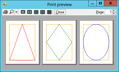
Figure 16-1: The PrintPreviewDialog lets the user zoom in and out, view the printout’s various pages, and send the printout to a printer.
The print preview dialog’s printer button on the left sends the printout to the currently selected printer. The magnifying glass button displays a drop-down that lets you select different scales. The next five buttons let the user display one, two, three, four, or six of the printout’s pages at the same time. The Close button closes the dialog box and the Page up/down arrows let you move through the printout’s pages.
The PrintPreviewControl displays a print preview much as the PrintPreviewDialog control does, except that it sits on your form. It does not provide all the buttons that the dialog box does, but it does provide methods that let you implement similar features. For example, your program can set the zoom level and the number of columns in the display.
The third thing you can do with a PrintDocument is assign it to a PrintDialog object’s Document property and then call the dialog’s ShowDialog method. This displays a dialog box that lets you select the printer and set its properties. For example, you can set the printer’s landscape or portrait orientation. When you click the dialog’s Print button, the dialog uses the PrintDocument object to send the printout to the printer.
The PrintShapes example program, which is available for download on this book’s website, displays a preview in a PrintPreviewControl, sends a printout directly to a printer, and displays the print preview dialog shown in Figure 16-1. At design time, I added a PrintPreviewControl, PrintDocument, and PrintPreviewDialog to the form. I set the Document properties for the preview control and the preview dialog to the PrintDocument object.
When the program starts, the PrintPreviewControl automatically generates and displays its preview.
The following code shows how the program sends a printout to the printer.
// Send the printout to the currently selected printer.
private void printButton_Click(object sender, EventArgs e)
{
    samplePrintDocument.Print();
}
The following code shows how the program displays the preview dialog.
// Display a print preview.
private void previewButton_Click(object sender, EventArgs e)
{
    samplePrintPreviewDialog.ShowDialog();
}
Finally, the following code shows the most interesting part of the program in which the PrintDocument generates the printout.
// The next page number to print.
private int NextPage = 0;

// Start with page number 0.
private void samplePrintDocument_BeginPrint(object sender,
    System.Drawing.Printing.PrintEventArgs e)
{
    NextPage = 0;
}

// Print a page.
private void samplePrintDocument_PrintPage(object sender,
    System.Drawing.Printing.PrintPageEventArgs e)
{
    e.Graphics.SmoothingMode = SmoothingMode.AntiAlias;

    // Draw the margin bounds.
    e.Graphics.DrawRectangle(Pens.Orange, e.MarginBounds);

    // Draw a shape.
    int xmid = (e.MarginBounds.Left + e.MarginBounds.Right) / 2;
    int ymid = (e.MarginBounds.Top + e.MarginBounds.Bottom) / 2;
    switch (NextPage)
    {
        case 0:     // Triangle.
            Point[] trianglePoints =
            {
                new Point(xmid, e.MarginBounds.Top),
                new Point(e.MarginBounds.Right, e.MarginBounds.Bottom),
                new Point(e.MarginBounds.Left, e.MarginBounds.Bottom),
            };
            e.Graphics.DrawPolygon(Pens.Red, trianglePoints);
            break;
        case 1:     // Diamond.
            Point[] diamondPoints =
            {
                new Point(xmid, e.MarginBounds.Top),
                new Point(e.MarginBounds.Right, ymid),
                new Point(xmid, e.MarginBounds.Bottom),
                new Point(e.MarginBounds.Left, ymid),
            };
            e.Graphics.DrawPolygon(Pens.Green, diamondPoints);
            break;
        case 2:     // Ellipse.
            e.Graphics.DrawEllipse(Pens.Blue, e.MarginBounds);
            break;
    }

    // Page 2 is the last page.
    e.HasMorePages = (++NextPage <= 2);
}
The code first defines the NextPage variable that it uses to keep track of which page it is printing.
The BeginPrint event handler executes before the PrintDocument starts to generate the printout. In this example, this event handler sets NextPage to 0 so that the program knows it is about to print the first page.
The PrintPage event handler does all the drawing. It starts by setting the Graphics object’s SmoothingMode property to make drawn shapes smoother. (Download the example, and comment this out to see what the difference is.)
Next, the program draws an orange rectangle showing the page’s margin bounds. Normally, anything you draw should be inside the margin bounds. (Don’t worry too much yet about how to draw shapes. The following sections explain drawing basics.)
Depending on the page number, the code then draws a triangle, diamond, or ellipse. The event handler finishes by incrementing NextPage and setting e.HasMorePages to true if the next page has a number less than or equal to 2.
The following sections provide a bit more information about how the Graphics object’s drawing methods work.
Drawing Basics
The previous section explains how the PrintShapes example program draws some simple shapes. It focuses mostly on the PrintPage event and glosses over exactly how the graphics are drawn.
A program uses three things to draw shapes: a Graphics object, pens, and brushes. It uses those things whether it is drawing on a Form, PictureBox, Bitmap, or print document.
The following sections describe Graphics objects, pens, and brushes.
Graphics Objects
A Graphics object represents a drawing surface. You can think of it as the canvas or paper on which the program will draw.
The Graphics class provides many methods for drawing lines, rectangles, curves, and other shapes. The following table summarizes these methods.
| Method | Description |
DrawArc | Draws an arc of an ellipse. |
DrawBezier | Draws a Bézier curve. |
DrawBeziers | Draws a series of Bézier curves. |
DrawClosedCurve | Draws a smooth closed curve that joins a series of points, connecting the final point to the first point. |
DrawCurve | Draws a smooth curve that joins a series of points but doesn’t connect the final point to the first point. |
DrawEllipse | Draws an ellipse. (To draw a circle, draw an ellipse with equal width and height.) |
DrawIcon | Draws an icon. |
DrawIconUnstretched | Draws an icon without scaling. If you know that you will not resize the icon, this is faster than DrawIcon. |
DrawImage | Draws an image. Bitmap is a subclass of Image, so you can use this method to draw a Bitmap. |
DrawImageUnscaled | Draws an image without scaling. If you know that you will not resize the image, this is faster than DrawImage. |
DrawLine | Draws a line. |
DrawLines | Draws a series of connected lines. This is much faster than using DrawLine repeatedly. |
DrawPath | Draws a GraphicsPath object. |
DrawPie | Draws a pie slice taken from an ellipse. |
DrawPolygon | Draws a polygon. This is similar to DrawLines except it connects the last point to the first point. |
DrawRectangle | Draws a rectangle with horizontal and vertical sides. (In other words, it can’t draw rotated rectangles.) |
DrawRectangles | Draws a series of rectangles. This is much faster than using DrawRectangle repeatedly. |
DrawString | Draws text. |
The methods listed in the preceding table draw the outline of something such as a line, rectangle, or ellipse. The Graphics class provides corresponding methods that fill many of these shapes. For example, the DrawRectangle method outlines a rectangle, and the corresponding FillRectangle method fills a rectangle. The filling methods include FillClosedCurve, FillEllipse, FillPath, FillPie, FillPolygon, FillRectangle, and FillRectangles.
The Draw methods take a pen as a parameter and use that pen to determine how the outline is drawn. In contrast, the Fill methods take a brush as a parameter and use the brush to determine how to fill the area.
The one exception is the DrawString method, which uses a brush to fill text even though its name begins with Draw.
The sections “Pens” and “Brushes” later in this chapter describe pens and brushes in greater detail.
See the online help for specific information about the Graphics class’s drawing and filling methods. You can find links to the pages describing these methods at the Graphics class’s web page msdn.microsoft.com/library/system.drawing.graphics.
Obtaining Graphics Objects
There are several ways a program can obtain a Graphics object on which to draw. You’ve already seen that the PrintDocument’s PrintPage event handler provides an e.Graphics parameter.
Similarly, a Form, PictureBox, or other control can provide a Paint event that includes an e.Graphics parameter on which a program can draw. The Paint event is raised when a control needs to redraw some or all of itself.
Note that the Graphics object included in a Paint event handler may clip its drawing methods, so it redraws only the parts of the control that actually need to be redrawn. That means any graphics drawn outside of those areas are ignored. You don’t need to do anything special to make this work. Just be aware that some of your graphics may not actually be drawn.
For example, if you want to redraw an entire PictureBox to cover it with random circles, you need to refresh the entire PictureBox to ensure that everything you draw appears. (You can refresh a control by calling its Refresh method.)
The last common way to obtain a Graphics object is to create one that is associated with a Bitmap. The program can then use the Graphics object to draw on the Bitmap. The following code demonstrates this technique.
private void Form1_Load(object sender, EventArgs e)
{
    // Make a Bitmap.
    Bitmap bitmap = new Bitmap(100, 100);
    using (Graphics graphics = Graphics.FromImage(bitmap))
    {
        // Draw an ellipse on it.
        graphics.DrawEllipse(Pens.Brown, 0, 0, 99, 99);
    }

    // Display it on the form.
    this.BackgroundImage = bitmap;
}
This code creates a 100 × 100 pixel Bitmap. (Coordinates for all graphics in .NET are in pixels.) It then uses the Graphics.FromImage method to create a Graphics object associated with the Bitmap. The Graphics class provides a Dispose method, so the program includes a using statement to ensure that the method is called when the program is done with the object.
Next, the code uses the Graphics object’s DrawEllipse method to draw a brown ellipse on the Bitmap. The code finishes by displaying the Bitmap in the form’s BackgroundImage property.
Pens
The Pen object determines how lines are drawn. It determines a line’s color, thickness, dash style, join style, and end cap style.
A program can explicitly create Pen objects, but often it can simply use one of the more than 280 stock pens that are predefined by the Pens class. For example, the following code draws a rectangle using a hot pink line that’s one pixel wide.
gr.DrawRectangle(Pens.HotPink, 10, 10, 50, 50)The following table summarizes the Pen class’s constructors.
| Constructors | Description |
Pen(brush) | Creates a pen of thickness 1 using the indicated Brush |
Pen(color) | Creates a pen of thickness 1 using the indicated color |
Pen(brush, thickness) | Creates a pen with the indicated thickness (a float) using a Brush |
Pen(color, thickness) | Creates a pen with the indicated thickness (a float) using the indicated color |
The following table describes some of the Pen class’s most useful properties and methods.
| Property or Method | Purpose |
Brush | Determines the Brush used to fill a line. |
Color | Determines the line’s color. |
CompoundArray | Lets you draw lines that are striped lengthwise. |
CustomEndCap | Determines a line’s end cap. |
CustomStartCap | Determines a line’s start cap. |
DashCap | Determines the cap drawn at the ends of dashes. This can be Flat, Round, or Triangle. |
DashOffset | Determines the distance from the start of a line to the start of its first dash. |
DashPattern | An array of floats that specifies a custom dash pattern. The array entries tell how many pixels to draw, skip, draw, skip, and so forth. These values are scaled if the pen is not one pixel wide. |
DashStyle | Determines the line’s dash style. This value can be Dash, DashDot, DashDotDot, Dot, Solid, or Custom. If you set the DashPattern property, this value is automatically set to Custom. The dashes and gaps between them are scaled if the pen is not one pixel wide. |
EndCap | Determines the cap used at the end of the line. This can be ArrowAnchor, DiamondAnchor, Flat, NoAnchor, Round, RoundAnchor, Square, SquareAnchor, Triangle, and Custom. If LineCap is Custom, you should use a CustomLineCap object to define the cap. |
LineJoin | Determines how lines are joined by methods that draw connected lines such as DrawLines and DrawPolygon. This value can be Bevel, Miter, and Round. |
SetLineCap | Specifies the pen’s StartCap, EndCap, and LineJoin properties at the same time. |
StartCap | Determines the cap used at the start of the line. |
Width | The pen’s width. |
The PaintForm example program, which is available for download on this book’s website, uses the following code to demonstrate some of these properties as it draws two shapes on the program’s form.
private void Form1_Paint(object sender, PaintEventArgs e)
{
    e.Graphics.SmoothingMode = SmoothingMode.AntiAlias;

    // Draw a dashed ellipse.
    using (Pen ellipsePen = new Pen(Color.Black, 5))
    {
        ellipsePen.DashStyle = DashStyle.DashDotDot;
        e.Graphics.DrawEllipse(ellipsePen, 50, 50, 150, 100);
    }

    // Draw a polygon.
    using (Pen polygonPen = new Pen(Color.Gray, 10))
    {
        polygonPen.LineJoin = LineJoin.Bevel;
        Point[] points =
        {
            new Point(20, 20),
            new Point(200, 20),
            new Point(100, 50),
            new Point(260, 250),
            new Point(20, 170),
        };
        e.Graphics.DrawPolygon(polygonPen, points);
    }
}
The code creates a black pen of thickness 5. It sets the pen’s DashStyle property to DashDotDot and draws an ellipse with it.
Next, the code creates a gray pen of thickness 10. It sets the pen’s LineJoin property to Bevel and draws a polygon with it. Figure 16-2 shows the result.
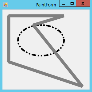
Figure 16-2: The PaintForm example program demonstrates dashed lines and beveled line joins.
You can learn more about the pen class at msdn .microsoft.com/library/system.drawing.pen.
Brushes
The Brush object determines how shapes are filled when you draw them using Graphics methods such as FillClosedCurve, FillEllipse, and FillRectangle. Different types of Brushes fill areas with solid colors, hatch patterns, color gradients, and images.
The Brush class is an abstract class, so you cannot make instances of the Brush class itself. Instead, you must create instances of one of the derived classes SolidBrush, TextureBrush, HatchBrush, LinearGradientBrush, and PathGradientBrush. The following table briefly describes these classes.
| Class | Purpose |
SolidBrush | Fills areas with a solid color |
TextureBrush | Fills areas with a repeating image |
HatchBrush | Fills areas with a repeating hatch pattern |
LinearGradientBrush | Fills areas with a linear gradient of two or more colors |
PathGradientBrush | Fills areas with a color gradient that follows a path |
The BrushSamples example program, which is available for download on this book’s website, uses the following code to demonstrate four kinds of brushes.
private void Form1_Paint(object sender, PaintEventArgs e)
{
    Rectangle rect = new Rectangle(10, 10, 120, 120);
    using (Brush solidBrush = new SolidBrush(Color.LightGray))
    {
        e.Graphics.FillRectangle(solidBrush, rect);
    }

    rect.Y += 130;
    using (Brush gradientBrush = new LinearGradientBrush(
        rect, Color.Black, Color.White, 45.0f))
    {
        e.Graphics.FillRectangle(gradientBrush, rect);
    }

    rect = new Rectangle(140, 10, 120, 120);
    using (Brush textureBrush = new TextureBrush(Properties.Resources.Smiley))
    {
        e.Graphics.FillRectangle(textureBrush, rect);
    }

    rect.Y += 130;
    using (Brush hatchBrush = new HatchBrush(
        HatchStyle.DiagonalBrick, Color.Black, Color.White))
    {
        e.Graphics.FillRectangle(hatchBrush, rect);
    }
}
The code first creates a light gray solid brush and fills a rectangle.
Next, it moves the rectangle down 130 pixels and creates a linear gradient brush. The brush fills the rectangle starting with the color black and shading smoothly to the color white. The gradient’s direction is 45 so the colors shade from black in the upper-left corner to white in the lower-right corner. After creating the brush, the program fills the rectangle with it.
The program then creates a new rectangle. It makes a texture brush, passing the brush’s constructor the image stored in the program’s Properties.Resources.Smiley resource. (Use the Project ⇒ Properties menu, and select the Resources page to add image resources.) When the program uses the texture brush, the rectangle is filled with repeating copies of the image.
Finally, the program creates a HatchBrush that uses a diagonal brick pattern with a black foreground and white background. It finishes by filling a rectangle with the hatch brush. Figure 16-3 shows the result.
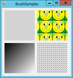
Figure 16-3: The BrushSamples example program fills four rectangles with different kinds of brushes.
You can learn more about the brush classes at msdn.microsoft.com/library/system .drawing.brush.
Drawing Text
Many printing applications draw text more than anything else, so the DrawString method is particularly important. This method has six overloaded versions. All take a string to draw, the font to draw it with, and a brush to determine the text’s appearance as their first three parameters.
Different versions let you specify the location for the text as X and Y float coordinates, a PointF (which has X and Y coordinates), or a RectangleF (which has top, left, width, and height values, again as floats).
The final variation in the overloaded versions is that some let you include a StringFormat object to determine the way the text is laid out. For example, the Alignment and LineAlignment properties determine the text’s horizontal and vertical alignment, respectively.
The DrawText example program, which is shown in Figure 16-4 and available for download on this book’s website, uses the following code to demonstrate two of the overloaded versions of DrawString.
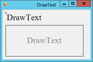
Figure 16-4: The DrawText example program draws text at a point and centered in a rectangle.
private void Form1_Paint(object sender, PaintEventArgs e)
{
    e.Graphics.SmoothingMode = SmoothingMode.AntiAlias;

    // Make a font.
    using (Font font = new Font("Times New Roman", 20))
    {
        // Draw text in the upper left corner.
        e.Graphics.DrawString("DrawText", font, Brushes.Black, 10, 10);
        e.Graphics.DrawLine(Pens.Black, 7, 7, 13, 13);
        e.Graphics.DrawLine(Pens.Black, 7, 13, 13, 7);

        // Draw text centered on the form.
        using (StringFormat sf = new StringFormat())
        {
            // Center vertically and horizontally.
            sf.Alignment = StringAlignment.Center;
            sf.LineAlignment = StringAlignment.Center;

            // Draw the text.
            Rectangle rect = new Rectangle(10, 50, 250, 100);
            e.Graphics.DrawRectangle(Pens.Black, rect);
            e.Graphics.DrawString("DrawText", font,
                Brushes.Gray, rect, sf);
        }
    }
}
After setting the SmoothingMode, the program creates a large font. It then draws the string “DrawText” using the font and a black brush at the point (10, 10). The DrawString method draws the text so its upper-left corner is just below that point.
The code then draws two lines to make an X over the point (10, 10) so you can see how the text is arranged with respect to this point.
Next, the program makes a StringFormat object. The object’s Alignment and LineAlignment properties can take the values Near (left or top alignment), Center (centered), or Far (right or bottom alignment). This program sets both properties to center the text.
The code then creates a Rectangle, draws the Rectangle, and then draws the text using the StringFormat object to center the text in the Rectangle.
Printing Images
The Graphics class’s DrawImage method draws an image. This method has 30 different overloaded versions. Some take the coordinates of a point where the image should be drawn. Others take rectangles or arrays of points to indicate which part of the image should be drawn at which location on the Graphics object. A few interesting versions let you map a rectangle to a parallelogram, possible flipping or skewing the image.
One of the more explicit versions takes a source rectangle that indicates the part of the image to print, and a destination rectangle that indicates where to print it.
The PrintImage example program, which is available for download on this book’s website, uses the following PrintPage event handler to print an image centered on a page.
private void imagePrintDocument_PrintPage(object sender,
    System.Drawing.Printing.PrintPageEventArgs e)
{
    Bitmap bm = Properties.Resources.GrandCanyon;

    // The source rectangle includes the whole picture.
    Rectangle sourceRect = new Rectangle(0, 0, bm.Width, bm.Height);

    // Center the destination rectangle.
    int x = e.MarginBounds.Left + (e.MarginBounds.Width - bm.Width) / 2;
    int y = e.MarginBounds.Top + (e.MarginBounds.Height - bm.Height) / 2;
    Rectangle destRect = new Rectangle(x, y, bm.Width, bm.Height);

    // Draw the image.
    e.Graphics.DrawImage(Properties.Resources.GrandCanyon,
        destRect, sourceRect, GraphicsUnit.Pixel);

    // There are no more pages.
    e.HasMorePages = false;
}
The code starts by setting the variable bm equal to the image resource named GrandCanyon. (Use the Project ⇒ Properties menu, and select the Resources page to add image resources.) The code could work directly with the image. The variable bm is just used to make the code easier to read.
Next, the program defines a source rectangle that includes the entire image. It then defines a destination rectangle that is the same size as the image and centered within the page’s margins.
The code then uses the DrawImage method to draw the entire image in the destination rectangle. It finishes by setting e.HasMorePages to false. Figure 16-5 shows the program’s print preview.
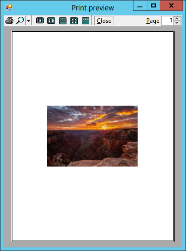
Figure 16-5: The PrintImage example program draws an image centered within the page’s margins.
A Booklet Example
The examples in this chapter so far have drawn simple shapes or text samples. This section describes a more complete and potentially useful example that prints a long series of paragraphs that may each use a different font size.
The PrintBooklet example program, which is available for download on this book’s website, breaks text into pages. It assumes you will print the pages double-sided and then staple the pages into a booklet. To allow extra room for the staples, the program adds a gutter to the margin of each page on the side where the staples will be. The program assumes the first page goes on the outside of the booklet, so it adds the gutter to the left margin on odd-numbered pages and to the right margin on even-numbered pages. Finally, the program displays a page number in the upper corner opposite the gutter.
In addition to demonstrating event handlers for the PrintDocument class’s events, this example shows how to use StringFormat objects to align text and break lines at word boundaries, wrap text within a target rectangle, and measure text to see how much will fit in a target rectangle.
Figure 16-6 shows the PrintBooklet program’s print preview dialog, so you can understand the goals. The figure isn’t big enough for you to read the text. The text (other than the headings) is gibberish anyway. It’s just there so that you can see the shape of the document.
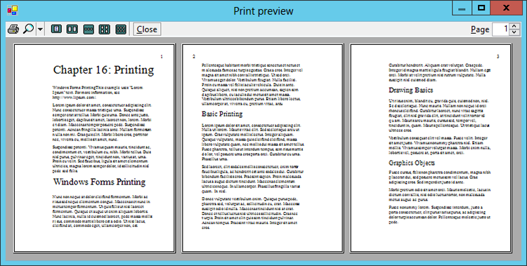
Figure 16-6: The PrintBooklet example program breaks text across pages, places a gutter on alternate sides, and draws page numbers on the side opposite the gutter.
If you look closely, you can see that the gutters are placed on alternate sides in odd and even pages. You can also see that the page numbers are in the upper corner on the side that doesn’t have the gutter.
The program uses the following ParagraphInfo structure to store information about the text it will print.
// Information about the paragraphs to print.
private struct ParagraphInfo
{
    public int FontSize;
    public string Text;
    public ParagraphInfo(int fontSize, string text)
    {
        FontSize = fontSize;
        Text = text;
    }
}
The following code shows how the program prepares the text it will print.
// The paragraphs.
private List<ParagraphInfo> AllParagraphs, ParagraphsToPrint;
private int PagesPrinted;

// Load the paragraph info.
private void Form1_Load(object sender, EventArgs e)
{
    // Make the text to print.
    AllParagraphs = new List<ParagraphInfo>();
    AllParagraphs.Add(new ParagraphInfo(45, "Chapter 16: Printing"));
    AllParagraphs.Add(new ParagraphInfo(16,
        "This example uses "Lorem Ipsum" text. For more information," +
        "see http://www.lipsum.com/."));
    ... Code to initialize other ParagraphInfo structures omitted ...
}
This code declares two List<ParagraphInfo> objects. The AllParagraphs list holds all the text to be printed. The ParagraphsToPrint list holds the text that hasn’t yet been printed while the program prints.
The Form1_Load event handler creates the AllParagraphs list and fills it with ParagraphInfo structures to print.
At design time I added a PrintDocument and PrintPreviewDialog to the program’s form as usual. When you click the program’s button Print Preview button, the program calls the dialog’s ShowDialog method to start the printing process. When printing starts, the following BeginPrint event handler executes.
// Prepare to print.
private void bookletPrintDocument_BeginPrint(object sender, PrintEventArgs e)
{
    // We have not yet printed any pages.
    PagesPrinted = 0;

    // Make a copy of the text to print.
    ParagraphsToPrint = AllParagraphs.ToList();
}This code sets PagesPrinted to 0 because no pages have been printed yet during this round of printing. It then copies the ParagraphInfo structures from the AllParagraphs list (which holds all the data) into the ParagraphsToPrint list (which holds those paragraphs that have not yet been printed).
Before it prints each page, the PrintDocument object raises its QueryPageSettings event. The program uses the following code to catch this event and prepare the next page for printing.
// Set the margins for the next page.
private void bookletPrintDocument_QueryPageSettings(object sender,
    QueryPageSettingsEventArgs e)
{
    // Use a 1 inch gutter. (Printer units are 1/100th inch).
    const int gutter = 100;

    // See if the next page will be the first, odd, or even.
    if (PagesPrinted == 0)
    {
        // The first page. Increase the left margin.
        e.PageSettings.Margins.Left += gutter;
    }
    else if ((PagesPrinted % 2) == 0)
    {
        // It's an odd page. Shift the margins right.
        e.PageSettings.Margins.Left += gutter;
        e.PageSettings.Margins.Right -= gutter;
    }
    else
    {
        // It's an even page. Shift the margins left.
        e.PageSettings.Margins.Left -= gutter;
        e.PageSettings.Margins.Right += gutter;
    }
}
This code positions the new page’s gutter. If this is the first page, then the page’s margins have their default values and do not include a gutter. In that case, the code increases the left margin to add a 1-inch gutter.
If this isn’t the first page, the code determines whether it is an odd or even page. If this is an even page, then the previous page was odd, so the gutter is currently on the left. To move the gutter to the right side of the page, the code adds 1 inch to the left margin and subtracts 1 inch from the right margin.
Similarly, if this is an even page, the code subtracts 1 inch from the left margin and adds 1 inch to the right margin.
After the QueryPageSettings event finishes, the PrintDocument object raises its PrintPage event to generate the next printed page. The program’s PrintPage event handler is fairly long, so the following paragraphs describe it in pieces. (Download the example to see it all in one chunk.)
The following code shows how the event handler starts.
private void bookletPrintDocument_PrintPage(object sender, PrintPageEventArgs e)
{
    // Increment the page number.
    PagesPrinted++;

    // Draw the margins (for debugging).
    //e.Graphics.DrawRectangle(Pens.Red, e.MarginBounds);

    // Print the page number right justified
    // in the upper corner opposite the gutter
    // and outside of the margin.
    int x;
    using (StringFormat sf = new StringFormat())
    {
        // See if (this is an odd or even page.
        if ((PagesPrinted % 2) == 0)
        {
            // This is an even page.
            // The gutter is on the right and
            // the page number is on the left.
            x = (e.MarginBounds.Left + e.PageBounds.Left) / 2;
            sf.Alignment = StringAlignment.Near;
        }
        else
        {
            // This is an odd page.
            // The gutter is on the left and
            // the page number is on the right.
            x = (e.MarginBounds.Right + e.PageBounds.Right) / 2;
            sf.Alignment = StringAlignment.Far;
        }

        // Print the page number.
        using (Font font = new Font("Times New Roman", 20,
            FontStyle.Regular, GraphicsUnit.Point))
        {
            e.Graphics.DrawString(PagesPrinted.ToString(),
                font, Brushes.Black, x,
                (e.MarginBounds.Top + e.PageBounds.Top) / 2,
                sf);
        }
The event handler starts by incrementing the number of pages printed so far. It then includes commented code to draw a rectangle around the page’s margins. Drawing this rectangle often makes debugging printing routines easier because it lets you see how your printing relates to the page’s margins.
Next, the code prepares to print the page number. It starts by creating a StringFormat object to align the page number. It sets the object’s Alignment property to left-justify page numbers in the left margin and to right-justify page numbers in the right margin. The code also calculates an X coordinate to place the page number halfway between the margin and the page’s bounds.
The code then creates the page number font and prints the page number at the point with the calculated X coordinate and halfway between the page’s upper margin and page bounds. Depending on the alignment, the text is arranged so that it is to the left or right of that point.
The following code shows how the program prepares to print text.
        // Draw the rest of the text left justified,
        // wrap at words, and don't draw partial lines.
        sf.Alignment = StringAlignment.Near;
        sf.FormatFlags = StringFormatFlags.LineLimit;
        sf.Trimming = StringTrimming.Word;

        // Draw some text.
        ParagraphInfo paragraphInfo;
        int ymin = e.MarginBounds.Top;
        RectangleF layoutRect;
        SizeF textSize;
        int charsFitted, linesFilled;
        while (ParagraphsToPrint.Count > 0)
        {
            // Print the next paragraph.
            paragraphInfo = ParagraphsToPrint[0];
            ParagraphsToPrint.RemoveAt(0);

            // Get the area available for this paragraph.
            layoutRect = new RectangleF(
                e.MarginBounds.Left, ymin,
                e.MarginBounds.Width,
                e.MarginBounds.Bottom - ymin);
            // Work around bug where MeasureString
            // thinks characters fit if (height <= 0.
            if (layoutRect.Height < 1) layoutRect.Height = 1;

            // See how big the text will be and
            // how many characters will fit.
            // Get the font.
            using (Font font = new Font("Times New Roman",
                paragraphInfo.FontSize, FontStyle.Regular, GraphicsUnit.Point))
            {
                textSize = e.Graphics.MeasureString(
                    paragraphInfo.Text, font,
                    new SizeF(layoutRect.Width, layoutRect.Height),
                    sf, out charsFitted, out linesFilled);
This code resets the StringFormat object’s properties to draw the text left-justified. Setting FormatFlags to LineLimit makes the program stop drawing when a complete line of text won’t fit in the formatting rectangle. By default, a line would be drawn even if its bottom edge would stick out of the rectangle.
Setting Trimming to Word makes drawing stop when a complete word won’t fit on a line. (Other settings let you stop at the nearest character and add an ellipsis after the final word or character if there’s more text that wouldn’t fit.)
The program sets ymin to the page’s top Y coordinate and then enters a loop that runs as long as there are more paragraphs to print.
Inside the loop, the program gets the next paragraph to print and removes it from the ParagraphsToPrint list. It then creates a layout rectangle that contains the remaining space that is available for printing. Vertically this rectangle starts at the current Y coordinate ymin and extends to the bottom of the page. Horizontally the rectangle covers the width of the page.
Next, the code creates a font of the appropriate size for the paragraph. It then calls the e.Graphics .MeasureString method. The overloaded version of the method used by the program takes the paragraph’s text and font, a size, and the StringFormat object as input parameters. It returns through output parameters the number of characters and lines that will fit in the indicated size. The program uses that information to determine how much of the paragraph will fit in the formatting rectangle.
Having determined how much text will fit in the available space, the program uses the following code to print it.
                // See if any characters will fit.
                if (charsFitted > 0)
                {
                    // Draw the text.
                    e.Graphics.DrawString(paragraphInfo.Text,
                        font, Brushes.Black,
                        layoutRect, sf);

                    // Debugging: Draw a rectangle around the text.
                    //e.Graphics.DrawRectangle(Pens.Green,
                    //    layoutRect.Left,
                    //    layoutRect.Top,
                    //    textSize.Width,
                    //    textSize.Height);

                    // Increase the Y coordinate where the next
                    // piece of text can start.
                    // Add a little interparagraph spacing.
                    ymin += (int)(textSize.Height +
                        e.Graphics.MeasureString("M", font).Height / 2);
                }
            } // font
If any text fits in the layout rectangle, the program uses the DrawString method to print it. Commented out code lets you draw a rectangle around the text, again for debugging purposes.
The code then increases the available Y coordinate ymin by the height of the printed text plus half of an M character’s height (for paragraph spacing).
At this point, the program has printed as much of the current paragraph as will fit in the available space. When the page first starts printing, that is probably the entire paragraph. It’s only near the bottom of the page that a partial paragraph may be printed.
The following code shows how the program finishes printing the page.
            // See if (some of the paragraph didn't fit on the page.
            if (charsFitted < paragraphInfo.Text.Length)
            {
                // Some of the paragraph didn't fit.
                // Prepare to print the rest on the next page.
                paragraphInfo.Text = paragraphInfo.Text.
                    Substring(charsFitted);
                ParagraphsToPrint.Insert(0, paragraphInfo);

                // That's all that will fit on this page.
                break;
            }
        } // while
    } // sf

    // If we have more paragraphs, we have more pages.
    e.HasMorePages = (ParagraphsToPrint.Count > 0);
}
If some of the paragraph’s characters did not fit, the program resets the ParagraphInfo structure’s text so that it holds whatever text did not fit. It then inserts the ParagraphInfo at the beginning of the ParagraphsToPrint list so that it is printed first on the next page. It then breaks out of the while loop so that it stops printing paragraphs on this page.
If all the paragraph’s text did fit, the while loop continues printing the next paragraph. After the while loop ends, either because a paragraph didn’t fit completely or because all the paragraphs have been printed, this page is done. The code sets e.HasMorePages to true if there are more paragraphs in the ParagraphsToPrint list.
When the last page has been printed, the PrintDocument object raises its EndPrint event. The following code shows the EndPrint event handler.
private void bookletPrintDocument_EndPrint(object sender, PrintEventArgs e)
{
    ParagraphsToPrint = null;
}
In this program, the EndPrint event handler simply sets the ParagraphsToPrint list to null so that the garbage collector can later recycle its memory. In this program, the list doesn’t occupy much space, so freeing it is a small matter. In a program that allocated more elaborate data structures, cleaning up in this event handler might be more important.
WPF Printing
WPF programs have some big advantages over Windows Forms applications. For example, WPF controls are infinitely scalable. That means no matter how far you zoom in on a WPF control, the result is smooth and not pixelated.
WPF’s approach to printing makes particularly good use of this infinite scalability. To create a printout, a WPF application creates objects that represent whatever needs to be printed. The program can scale those objects as necessary to fit the printout and the result takes advantage of the printer’s capabilities.
There are several ways a WPF application can produce printouts. The following sections describe two of the more useful: using a paginator and creating documents.
Using a Paginator
A paginator is an object that generates a printout’s pages. To create a printout by using a paginator, you derive a new class from the DocumentPaginator class and override its GetPage method to create the document’s pages. You also need to override a few other methods to let the paginator know how many pages it will produce.
The WpfPrintShapes example program, which is available for download on this book’s website, uses a paginator to create a printout. Figure 16-7 shows the program’s three pages displayed in Microsoft Reader.
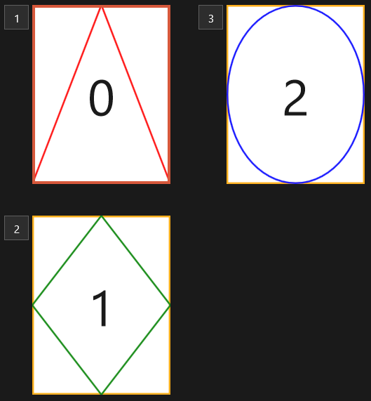
Figure 16-7: The WpfPrintShapes example program prints three pages.
When the WpfPrintShapes example program executes, it displays a Print button. When you click the button, the following code executes.
private void printButton_Click(object sender, RoutedEventArgs e)
{
    PrintDialog pd = new PrintDialog();
    if (pd.ShowDialog() == true)
    {
        // Print.
        pd.PrintDocument(
            new ShapesPaginator(
                new Size(pd.PrintableAreaWidth, pd.PrintableAreaHeight)),
            "Shapes");
    }
}
This code creates a PrintDialog object and calls its ShowDialog method to display it. If the user selects a printer and clicks Print, the ShowDialog method returns true. In that case, the program calls the dialog’s PrintDocument method, passing it a new ShapesPaginator object and a description of the document being printed.
When the program creates the ShapesPaginator object, it passes the constructor a Size structure representing the page’s printable area.
The ShapesPaginator object does all the interesting work of generating the document’s printed pages. The following code shows the ShapesPaginator class, except for the GetPage method, which is described shortly.
public class ShapesPaginator : DocumentPaginator
{
    // The area in which to print.
    private Size MyPageSize;

    // Save the page size.
    public ShapesPaginator(Size pageSize)
    {
        MyPageSize = pageSize;
    }

    // Create and return the requested page.
    public override DocumentPage GetPage(int pageNumber)
    {
        ...
    }

    // If pagination is in progress and PageCount is not final, return false.
    // If pagination is complete and PageCount is final, return true.
    // In this example, there is no pagination to do.
    public override bool IsPageCountValid
    {
        get { return true; }
    }

    // The number of pages paginated so far.
    // This example has exactly 3 pages.
    public override int PageCount
    {
        get { return 3; }
    }

    // The suggested page size.
    public override Size PageSize
    {
        get { return MyPageSize; }
        set { MyPageSize = value; }
    }

    // The element currently being paginated.
    public override IDocumentPaginatorSource Source
    {
        get { return null; }
    }
}
The ShapesPaginator class inherits from DocumentPaginator. The class starts by declaring a private MyPageSize variable to hold the available printing area. The class’s constructor takes a Size parameter and saves it in MyPageSize.
To produce a printout, the class overrides the following four properties.
IsPageCountValid—Some programs may need to paginate all the printout’s pages before the finalPageCountvalue is correct. In that case, this property should returnfalsewhile pagination is occurring andtrueafterPageCountis set to its final correct value.PageCount—Returns the number of pages that have been formatted.PageSize—Gets or sets the suggested size of the printed page.Source—Returns the element being paginated.
The WpfPrintShapes example just prints three pages, so these overridden properties are relatively simple. The program doesn’t need to format all the pages to determine how many pages there will be, so IsPageCountValid always returns true, PageCount always returns 3, PageSize returns the size saved by the class’s constructor, and Source returns null.
In a Windows Forms application, a PrintDocument raises a PrintPage event to generate a printed page. Similarly, when a WPF application uses a paginator, it calls the paginator’s GetPage method to get objects representing a printed page. The following code shows the GetPage method used by the ShapesPaginator class.
// Create and return the requested page.
public override DocumentPage GetPage(int pageNumber)
{
    // Create a grid.
    Grid grid = new Grid();
    grid.Width = MyPageSize.Width;
    grid.Height = MyPageSize.Height;
    // Outline the drawing area.
    Rectangle rectangle = new Rectangle();
    rectangle.Width = MyPageSize.Width;
    rectangle.Height = MyPageSize.Height;
    rectangle.Stroke = Brushes.Orange;
    rectangle.StrokeThickness = 10.0;
    grid.Children.Add(rectangle);

    // Display the page number.
    TextBlock textBlock = new TextBlock();
    textBlock.Text = pageNumber.ToString();
    textBlock.FontSize = 300;
    textBlock.HorizontalAlignment = HorizontalAlignment.Center;
    textBlock.VerticalAlignment = VerticalAlignment.Center;
    grid.Children.Add(textBlock);

    // Generate the appropriate page.
    switch (pageNumber)
    {
        case 0:     // Triangle.
            Polygon triangle = new Polygon();
            triangle.Stroke = Brushes.Red;
            triangle.StrokeThickness = 10.0;

            PointCollection triangle_pts = new PointCollection();
            triangle_pts.Add(new Point(MyPageSize.Width / 2, 0));
            triangle_pts.Add(new Point(MyPageSize.Width, MyPageSize.Height));
            triangle_pts.Add(new Point(0, MyPageSize.Height));
            triangle.Points = triangle_pts;
            grid.Children.Add(triangle);
            break;

        case 1:     // Diamond.
            Polygon diamond = new Polygon();
            diamond.Stroke = Brushes.Green;
            diamond.StrokeThickness = 10.0;

            PointCollection diamond_pts = new PointCollection();
            diamond_pts.Add(new Point(MyPageSize.Width / 2, 0));
            diamond_pts.Add(new Point(MyPageSize.Width, MyPageSize.Height / 2));
            diamond_pts.Add(new Point(MyPageSize.Width / 2, MyPageSize.Height));
            diamond_pts.Add(new Point(0, MyPageSize.Height / 2));
            diamond.Points = diamond_pts;
            grid.Children.Add(diamond);
            break;

        case 2:     // Ellipse
            Ellipse ellipse = new Ellipse();
            ellipse.Stroke = Brushes.Blue;
            ellipse.StrokeThickness = 10.0;
            ellipse.Width = MyPageSize.Width;
            ellipse.Height = MyPageSize.Height;
            grid.Children.Add(ellipse);
            break;
    }

    // Make the grid arrange itself and its controls.
    Rect rect = new Rect(new Point(0, 0), MyPageSize);
    grid.Arrange(rect);

    // Wrap the grid in a DocumentPage and return it.
    return new DocumentPage(grid);
}
The code starts by creating a Grid control and making it fit the available print area.
Next, the program creates a Rectangle and makes it fit the available area. It sets the Rectangle’s Stroke properties to draw an orange outline 10 pixels wide and adds the Rectangle to the Grid’s children.
The code then creates a TextBlock to display the page number. It sets the object’s text, font size, and alignment. It then adds the TextBlock to the Grid’s children.
By now you can probably see the pattern. The code creates a new object to represent some output, sets its properties, and adds the object to the Grid’s children.
Now, depending on the page number, the code creates a polygon representing a triangle, a polygon representing a diamond, or an ellipse.
After creating the content controls, the method calls the Grid’s Arrange method to make it arrange its controls. It finishes by returning a new DocumentPage object. It passes the DocumentPage constructor the root visual object that it should contain (the Grid in this example).
Creating Documents
By using paginator objects as described in the preceding section, you can produce just about any document you like, at least in theory. In practice creating a layout for a complicated multipage printout with paragraphs flowing around pictures, tables, and charts would be a huge amount of work. The FlowDocument and FixedDocument classes make this sort of complex layout task much easier.
FlowDocuments
A FlowDocument object holds other objects that represent graphical output such as text, images, and shapes. It arranges its objects to take best advantage of whatever space is available, much as a web browser rearranges its contents when it is resized.
There isn’t room here to completely cover XAML, and all the objects that can be contained in a FlowDocument, but the WpfFlowDocument program, which is shown in Figure 16-8 and available for download on this book’s website, can serve as a small example.
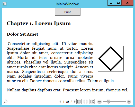
Figure 16-8: A FlowDocument rearranges its contents much as a web browser does when it is resized.
The following code shows the XAML used by the WpfFlowDocument program.
<Window x:Class="WpfFlowDocument.MainWindow"
        xmlns="http://schemas.microsoft.com/winfx/2006/xaml/presentation"
        xmlns:x="http://schemas.microsoft.com/winfx/2006/xaml"
        Title="WpfFlowDocument" Height="350" Width="525">
    <Grid>
        <Grid.RowDefinitions>
            <RowDefinition Height="30"/>
            <RowDefinition Height="*"/>
        </Grid.RowDefinitions>
        <Button Grid.Row="0"
            Content="Print" Click="printButton_Click"
            Width="100" Height="30" VerticalAlignment="Top"/>
        <FlowDocumentReader Grid.Row="1" VerticalAlignment="Top">
            <FlowDocument Name="sampleFlowDocument">
                <Paragraph FontSize="20" FontWeight="Bold">
                    Chapter 1. Lorem Ipsum
                </Paragraph>

                <Paragraph FontSize="16" FontWeight="Bold">
                    Dolor Sit Amet
                </Paragraph>

                <Paragraph>
                    <Floater HorizontalAlignment="Right">
                        <Paragraph>
                            <Grid Width="100" Height="100">
                                <Border BorderBrush="Black" BorderThickness="1"/>
                                <Polygon
                                    Points="50,5 95,50 50,95 5,50"
                                    Stroke="Black" StrokeThickness="5" />
                            </Grid>
                        </Paragraph>
                    </Floater>
                    Consectetur adipiscing elit ...
                </Paragraph>

                <Paragraph>
                    Nullam dapibus dapibus ...
                </Paragraph>

                <Paragraph>
                    Etiam lacus eros ...
                </Paragraph>

            </FlowDocument>
        </FlowDocumentReader>
    </Grid>
</Window>
The XAML code begins with a Window element that represents the program’s window. That element contains a Grid with two rows: one that is 30 pixels tall and one that occupies the Grid’s remaining vertical space.
Next, the code defines a Print Button in the Grid’s first row. The code then defines a FlowDocumentReader to display the FlowDocument.
The FlowDocument element contains a sequence of Paragraph elements. The first two Paragraphs define headings. The third includes a Floater element. A Floater represents content that can be moved if necessary and around which other text can flow. In Figure 16-8 you can see how the text flows around the Floater on the right.
In this example, the Floater contains a Paragraph that holds a Grid. The Grid contains a Border and a Polygon.
The Floater is followed by more text in the same Paragraph.
Finally, the FlowDocument contains two other Paragraphs.
Printing a FlowDocument involves the following short but confusing sequence of steps.
- Display a
PrintDialogas usual. - Make an
XpsDocumentWriterassociated with thePrintDialog’s selected printer’s queue. - Cast the
FlowDocumentinto anIDocumentPaginatorSource. - Use the
XpsDocumentWriter’sWritemethod to write into the print queue. Pass the method a paginator obtained by calling theFlowDocument’sDocumentPaginatorproperty.
The following code shows how the WpfFlowDocument example prints.
private void printButton_Click(object sender, RoutedEventArgs e)
{
    PrintDialog pd = new PrintDialog();
    if (pd.ShowDialog() == true)
    {
        // Make an XPS document writer for the print queue.
        XpsDocumentWriter xpsWriter =
            PrintQueue.CreateXpsDocumentWriter(pd.PrintQueue);

        // Turn the FlowDocument into an IDocumentPaginatorSource.
        IDocumentPaginatorSource paginatorSource =
            (IDocumentPaginatorSource)sampleFlowDocument;

        // Write into the writer using the document's paginator.
        xpsWriter.Write(paginatorSource.DocumentPaginator);
    }
}
FixedDocuments
Like a FlowDocument, a FixedDocument holds graphical objects. Instead of rearranging its objects as space permits, a FixedDocument always places its objects in the same positions. This is similar to the way a PostScript document displays items at fixed positions.
The WpfFixedDocument example program, which is shown in Figure 16-9, and available for download on this book’s website, displays and prints a FixedDocument.
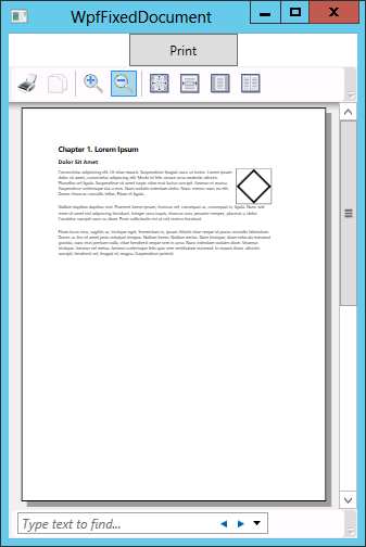
Figure 16-9: A FixedDocument positions its contents in set positions on a fixed page.
The code to print a FixedDocument is similar to the code shown in the preceding section for printing a FlowDocument.
To display a FixedDocument in XAML code, include a DocumentViewer to hold the FixedDocument. Give the FixedDocument one or more PageContent elements to represent the printed pages. Each of those should hold a FixedPage element to generate content for the pager.
The following code shows the piece of XAML code used by the WpfFixedDocument example program to display its contents.
<DocumentViewer Grid.Row="1">
    <FixedDocument Name="sampleFixedDocument">
        <PageContent Width="850" Height="1100">
            <FixedPage Width="850" Height="1100" Margin="100">
                ... Page 1 content elements ...
            </FixedPage>
        </PageContent>
        <PageContent Width="850" Height="1100">
            <FixedPage Width="850" Height="1100" Margin="100">
                ... Page 1 content elements ...
            </FixedPage>
        </PageContent>
    </FixedDocument>
</DocumentViewer>
The details about how the program generates its content are long and not very interesting, so they aren’t included here. They just use a long sequence of StackPanel, TextBlock, Grid, and other controls to create the output. Download the example and look at the code to see how it works.
Summary
Windows Forms and WPF take different approaches to printing. In a Windows Forms application, a PrintDocument object represents a printout. It raises events such as BeginPrint and PrintPage to let the program determine what is printed. In the PrintPage event handler, you use Graphics, Pen, and Brush objects to produce output.
WPF applications use objects more directly to represent items to be printed. When you use a paginator, you derive a class from DocumentPaginator and you override the class’s GetPage method to produce output. That output takes the form of a DocumentPage object containing other objects such as TextBlock, Rectangle, and Polygon objects that generate printed results.
If you prefer to use a FlowDocument or FixedDocument to produce output, you also use objects such as TextBlock, Rectangle, and Polygon to generate printed results. If you place the FlowDocument or FixedDocument inside a FlowDocumentReader or DocumentViewer, you can even use them as previews for the printout they will produce.
The programs described before this chapter interact only with the user. Printing is one way a program can interact with some other part of the system. The next chapter describes some other ways that a C# program can interact with the system by storing configuration and resource values for later use. These techniques let a program store and recover information between runs.
Exercises
To save paper, you may want to make all printing programs display print previews instead of printing.
- Write a Windows Forms program that uses 20-pixel-wide blue lines to draw five-, seven-, and nine-pointed stars centered on three pages, as shown in Figure 16-10.
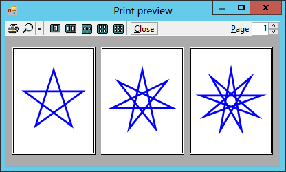
Figure 16-10: For Exercise 1, make a program that prints five-, seven-, and nine-pointed stars.
Hint: You can use the following code to generate points for the stars.
private List<PointF> StarPoints(float centerX, float centerY,
    float radius, int numPoints)
{
    // Calculate the difference in angles between points.
    double dtheta = (2 * Math.PI / numPoints) * (int)(numPoints / 2);

    // Generate the points.
    List<PointF> points = new List<PointF>();
    double theta = -Math.PI / 2;
    for (int i = 0; i < numPoints; i++)
    {
        double x = centerX + radius * Math.Cos(theta);
        double y = centerY + radius * Math.Sin(theta);
        points.Add(new PointF((float)x, (float)y));
        theta += dtheta;
    }

    return points;
}
- Make a Windows Forms program that draws your name as large as possible centered inside the page’s margins. (Hint: Use the
Graphicsobject’sMeasureStringmethod to see how big the string will be when drawn with a particular font. Try fonts of different sizes until you find the largest that works. You only need to try integral font sizes.) - Make a Windows Forms program that generates prime numbers and prints them one per line in a 12-point font until it reaches the bottom of the page. Draw the margin bounds to verify that your text doesn’t go beyond them. (Hints: Use 1.2 times the height of an M for the spacing between lines. To generate primes, use the
AllPrimesiterator you built for Exercise 8 in Chapter 14, “Collection Classes.”) - Repeat Exercise 1 with a WPF program that uses a paginator.
- Repeat Exercise 1 with a WPF program that uses a
FixedDocument. Hint: You don’t need to create the stars at design time in XAML code. When the window loads, use code to add pages containing the stars to theFixedDocument. (This book doesn’t explain how to build WPF interfaces in code, but you should be able to figure it out with a little experimentation. Create newPageContent,FixedPage,Grid, andPolygonobjects. Add them to the appropriate objects’PagesorChildrencollections. If you get stuck, look at the solution in Appendix A “Solutions to Exercises,” and download the program described there.)