
Introducing dynamic blocks, external references (xrefs), and raster images
Authoring dynamic blocks
Attaching and managing xrefs and DWFs
Controlling xref paths
Attaching and managing raster image files
In Chapter 17, I introduce blocks as collections of object geometry that are treated as single entities in AutoCAD. In that chapter, I also describe giving blocks a little more oomph by adding attributes — changeable text tags that can differ with each insertion. Other than that kind of slight variation though, the blocks I describe in Chapter 17 tend to be pretty static.
But blocks don't have to be static creations. Instead of having a half-dozen regular blocks for a half-dozen different door sizes, you can create a single dynamic block that includes all those sizes. Unlike a regular block, in which every instance of a particular block is geometrically identical, each instance of a dynamic block can display geometric variations. For example, you can insert one furniture block three times and have one instance display as a sofa, one as a loveseat, and one as an armchair. I introduce block authoring — the process for creating and editing dynamic blocks — in this chapter.
An external reference drawing, or xref, is like an industrial-strength block. An xref is a pointer to a separate drawing outside the drawing you're working on. When you attach a reference drawing, it appears on-screen and on plots as part of your drawing, but it continues to live as a separate document on your hard drive. If you edit the externally referenced drawing, the appearance of the drawing changes in all drawings that reference it.
A raster image file stores a graphical image as a series of dots. Raster files are good for storing photographs, logos, and other images, whereas AutoCAD vector files are good for storing geometrical objects such as lines and arcs, along with text and other annotations for describing the geometry. Sometimes it's handy to combine raster images with AutoCAD vector files by attaching them to your drawing files, and the External References palette makes the process straightforward.
Note
Before AutoCAD 2007, external references were AutoCAD drawing files that you attached to your current drawing. Images were (and still are) raster graphics files that you attached in a similar way but with a different command. In AutoCAD 2007 and later, External References is the name of the palette with which you attach and manage not only externally referenced AutoCAD drawings (xrefs) and 2D MicroStation DGN drawing files, but also image files and DWF underlays. (DWF stands for Design Web Format; a DWF is a "lightweight" version of a DWG file intended for design review or posting on a web site.) I discuss attaching DWFs as external references at the end of this chapter, and describe the Web functions of DWFs in Chapter 19.
Both AutoCAD 2009 and AutoCAD LT 2009 enable you to attach DGN files to current drawings via the External References palette. DGN files are drawing files created by one of AutoCAD's major competitors: MicroStation from Bentley Systems. (You can also import and export DGN drawing data in both AutoCAD and AutoCAD LT.) If you're new to AutoCAD, you're not so likely to encounter DGN files unless you're working for a large company that exchanges a lot of drawings with partners and consultants. For more information on DGN files in AutoCAD 2009, look up "DGN Files, About" in the online help system index.
As I mention in Chapter 17, blocks, external references, DWF underlays, raster images, and DGN files enable you to reuse your work and the work of others, giving you the potential to save tremendous amounts of time — or to cause tremendous problems if you change a file on which other people's drawings depend. Use these features when you can to save time, but do so in an organized and careful way so as to avoid problems.
You can add variety to your blocks by making them dynamic. The two most useful applications for dynamic blocks are multiple presentations of similar objects and manipulation of components within individual block inserts.
There's no question that AutoCAD's dynamic blocks feature gives a great deal of flexibility to block creation and insertion. But it's also a very complicated system, with its own set of commands and system variables. I recommend that you become very familiar with the regular block creation and insertion techniques I describe in Chapter 17 before you tackle dynamic blocks.
Tip
Spend some time planning your dynamic blocks. Sketch out the geometry for each variation in appearance (or visibility state) and decide where the common base point should be. Unless you're a lot smarter than I am, you'll probably find that creating dynamic blocks is complex enough without trying to design your blocks as you go.
If your drawing shows six different kinds of windows, one approach is to create six different standard blocks to represent them all. Alternatively, you can create a single dynamic block and define visibility states to cover all six different types. The following steps show you how to make your blocks do double (or sextuple?) duty by using the Edit Block Definition dialog box:
Open a drawing that contains some block definitions you'd like to combine or draw some simple geometry to make some similar types of objects.
You can create dynamic blocks from scratch, or you can work with existing standard (that is, non-dynamic) block definitions. Figure 18-1 shows a drawing with three non-dynamic blocks.
On the Block panel of the Home tab, choose Edit (or choose Tools

In the Block to create or edit box, specify a new block name or click <Current Drawing> and then click OK to display the Block Editor window.
The Block Editor is a special authoring environment with its own set of controls and a passel of command-line commands. You also have access to the rest of the Ribbon panels (or toolbars), so you can draw and edit just like you're in the regular drawing window.
If you enter a new block name, AutoCAD displays an empty block-authoring environment where you draw geometry or insert existing blocks. If you instead select Current Drawing, AutoCAD places all drawing objects inside the block authoring environment.
Create some geometry for the first visibility state or choose Insert on the Block panel (on the classic menu bar choose Insert
When creating geometry from scratch, pay attention to where the common base point should be. Although you use different blocks to assemble a multiple-view block, they should all have the same base point (0,0 is a good one for blocks). You don't want your chairs jumping around between different insertion points!
If you inserted an existing block in Step 4, deselect all three Specify On-Screen check boxes, make sure that the Explode check box is not selected, and then click OK.
Repeat Steps 4 and 5, drawing or inserting all the necessary geometry.
At this point, your drawing screen may look pretty strange (see Figure 18-2). Don't worry; you're going to fix it up in the next steps.
Click the Parameters tab of the Block Authoring palettes and then click Visibility Parameter.
If the palettes aren't open, click Block Authoring Palettes on the Tools panel on the highlighted Block Editor section of the Ribbon (or on the Block Authoring toolbar in the AutoCAD Classic workspace).
AutoCAD prompts you to specify the parameter location.
Click to place the parameter marker somewhere other than the base point location you chose in Step 4.
The parameter location you specify will be the spot on the block where the dynamic block option grip will be displayed. It's not crucial where you locate this point, but try to pick a sensible location on the object. If you specify the same point for the parameter location as the base point for the block, you may have a hard time selecting the dynamic option grip.
AutoCAD places a parameter marker at the selected point and returns to the command line.
As shown in Figure 18-2, the label Visibility appears next to the Visibility Parameter marker, and a yellow Alert symbol indicates that no action has been assigned to the parameter yet. The controls on the Ribbon's Visibility panel (or at the right end of the classic Block Authoring toolbar) become active.
Click Visibility States on the Visibility panel (or the Block Authoring toolbar). Click Rename and change VisibilityState0 to something more descriptive. Click OK.
As is the case with other named objects in AutoCAD, it's good procedure to assign useful, descriptive names rather than accept the default generic labels.
On the Visibility panel or the classic toolbar, click Make Invisible. At the Select objects prompt, select the geometry or block inserts that should be invisible in the current visibility state — that is, those that are not associated with the current visibility state — and then press Enter.
By default, the invisible objects disappear from the screen. You can view them in a faded appearance by clicking Visibility Mode on the ribbon or the AutoCAD Classic toolbar.
Click Visibility States again and then click New to create a new visibility state. In the New Visibility State dialog box, enter a descriptive name. Select the Show All Existing Objects in New State radio button, and then click OK.
All of your geometry should reappear.
Repeat Steps 10, 11, and 12 to create additional visibility states associated with the remaining geometry or blocks.
The geometry or block insert associated with the last-created visibility state should be visible on-screen.
Click Close Block Editor on the Ribbon (or the Block Authoring toolbar). Save the changes to your new block or to <Current Drawing>.
AutoCAD displays an alert box asking if you want to save changes to your block. Click Cancel to return to the block editor or No to discard your edits. Click Yes to save. AutoCAD closes the block authoring environment and returns to the standard drawing editor window.


You can modify the appearance of individual instances of the same block by defining parameters and actions to move, rotate, flip, or align parts of them. You can adjust the block's appearance as you insert it or at any time afterward. The following steps show you how to use the Block Editor to add some action to a block definition:
Open a drawing that contains some block definitions whose appearance you'd like to spice up a little, or draw some simple geometry that might make a suitably dynamic block.
Action parameters are most effective in block definitions that contain groups of related objects — for example, an office desk and chair or a furniture arrangement.
On the Block panel of the Ribbon's Home tab, choose Edit (or choose Tools
In the Block to create or edit field, type a new block name or click <Current Drawing>, and then click OK.
Create some geometry or insert some blocks. When inserting blocks, remember to make sure that the Explode check box at the lower-left corner of the Insert dialog box is not selected, and then click OK.
Draw the geometry or insert the blocks in a group such that you can insert the finished arrangement into your drawings — for example, Figure 18-3 shows the creation of a dynamic block for a coffee shop or cafeteria.
Repeat Step 4 until you've drawn all the needed geometry or inserted all the necessary blocks.
Click the Parameters tab of the Block Authoring palettes and then click Rotation Parameter.
AutoCAD prompts you to specify the parameter location.
Click to place the parameter marker somewhere on the object geometry other than the base point location.
If you specify the same point for the parameter location as the base point for the block, you may have a hard time selecting the dynamic option grip.
AutoCAD places a parameter marker at the selected point and returns to the command line, prompting you to specify the radius of the rotation parameter, the default rotation angle, and finally the parameter label location.
The parameter marker's label appears next to the rotation parameter marker.
Click the Actions tab of the Block Authoring palettes and then click Rotate Action. Select the Rotate Parameter, select the objects that should be modified when the grip is used, and specify a point for the action's label.
AutoCAD returns to the command prompt. At this point, it's fine to go with default values and on-screen pick points.
Repeat Steps 6 through 9, trying different parameters and actions. For example, choose a Point Parameter and a Move Action.
Figure 18-3 shows a set of block components, several of which have action parameters assigned to them. After the block is inserted, you can manipulate the components to which you've added parameters to vary the appearance of the blocks. I explain how a little later in this chapter.
Click Close Block Editor on the Ribbon (or AutoCAD Classic's Block Authoring toolbar).
An AutoCAD alert box asks if you want to save changes to your block. Click Yes to save changes to your new block or <Current Drawing>.
AutoCAD closes the block-authoring environment and returns to the standard drawing editor window.
After a dynamic block has been inserted in a drawing, you can select it and modify its display through a special set of custom grips. (That's what AutoCAD calls them, so I'm following suit.)
Note
When you select a non-dynamic block, you see a single grip at the insertion point. When you select a dynamic block, you see at least two — and maybe more — custom grips, as well as the insertion point grip. The custom grips usually look different from the regular object grips, but not always, so take care when clicking grips.

The following steps show you how to make your dynamic blocks do the things you just spent all this time teaching them to do:
Insert a few blocks that contain some dynamic parameters such as visibility or action parameters.
If your block inserts don't have any action parameters, go to Step 4.
Select a block that includes some action parameters.
The block insert displays a number of grips (see Figure 18-4). If the insert displays only one grip, it isn't a dynamic block.
Click one of the custom grips — for example, clicking a round grip opens the rotation parameter of the object. Rotate the component as required.
Select a block that includes a visibility parameter and then click the visibility grip. Choose the desired visibility state from the right-click menu.
For additional information on manipulating actions and visibility states, refer to the online help system.
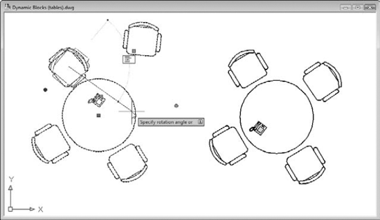
Figure 18-4. Variations on dynamic blocks (original on the right, and a handy grip tip on a chair at left center).
Dynamic blocks, as I've suggested more than once, are a powerful — and complicated — feature. The Block Authoring Palettes contain 10 selectable parameters, 8 actions, and 20 parameter sets. I'm thinking of writing a new book called AutoCAD Block Authoring For Dummies (although, truth be told, it may never happen). Until I do, AutoCAD's online help system is your best resource for more information on all the possibilities of dynamic blocks. The quickest and most direct way to AutoCAD's own help is to click the Learn about Dynamic Blocks button in the Block Editor Ribbon's Tools panel (refer to Figure 18-3).
In AutoCAD, an xref, or external reference, is a reference to another, external drawing file — one outside the current drawing — that you can make act as though it's part of your drawing. Technically, a reference is simply a pointer from one file to another. The xref is the actual pointer, but many people call the combination of the pointer and the external file the xref.
In AutoCAD 2009, external drawing files are just one of four different file types you can attach to your current drawing by using the somewhat confusingly named External References palette. You use this palette to attach externally referenced AutoCAD drawings (xrefs), raster image files, DWF files, and MicroStation DGN drawing files. It's really worth getting past the confusion — it's very useful to be able to see externally referenced drawing files, attached images, DWF underlays (and maybe even MicroStation drawing files) all in the same window.
When you attach an external drawing to your current drawing, you become the host of the external file. No need to break out the cocktails and canapés though . . . it's actually your current drawing that's doing the hosting and in AutoCAD, it's called (what else?) the host drawing. You can think of the attached xrefs as guests, but most of the time they're pretty well-behaved ones, and like the best of guests, they go away as soon as you want them to.
Xrefs have a big advantage over blocks: If a drawing is inserted as a block into another drawing, its geometry doesn't change if the original drawing is changed in any way — it always looks the way it looks when it's inserted. If that drawing is attached as an xref, however, AutoCAD will automatically update every host drawing to which it's attached when the host drawing is reopened. You can also manually reload the changed xref if you don't want to close and reopen the host drawing.
When you open a drawing that contains xrefs, AutoCAD displays a little symbol (which looks like papers with a binder clip) on the right end of the status bar. This symbol alerts you to the fact that some of the things you see in the drawing are actually parts of other, xrefed drawings. If an xref changes while you have the host drawing open (because you or someone else opens and saves the referenced drawing), the status bar xref symbol displays an External Reference Files Have Changed balloon notification (in AutoCAD but not in AutoCAD LT). Simply click the Reload link in the balloon notification to show the updated xrefs. (If you want to change how AutoCAD checks for changes, look up "XREFNOTIFY" in the online help.)
Note
AutoCAD LT doesn't automatically check for changed references, nor is there an XREFNOTIFY variable in LT. The thinking at Autodesk is that external references are more for the big guys who play with the full program, not LT users who are less likely to be working on huge projects or working collaboratively — places where xrefs pay large dividends.
In both AutoCAD and AutoCAD LT, you can use the Reload option on the External References palette to update the xrefs. See the "Managing xrefs" section, later in this chapter, for details.
Another advantage that xrefs have over blocks is that their contents aren't stored in your drawing even once. The disk storage space taken up by the original drawing (that is, the xref) isn't duplicated, no matter how many host drawings reference it. This characteristic makes xrefs much more efficient than blocks for larger drawings that are reused several times.
You can always buy a larger hard drive, however, so the storage issue isn't crucial. The key benefit of xrefs is that they enable you to organize your drawings so that changes you make to a single drawing file automatically "ripple through" all the host drawings into which it's xrefed. This benefit is even greater on larger projects involving multiple drafters, each of whose work may be incorporated in part or in whole in the work of others.
Warning
The automatic update feature of xrefs is a big advantage only if you're organized about how you use xrefs. Suppose that an architect creates a plan drawing showing a building's walls and other major features that are common to the architectural, structural, plumbing, and electrical plan drawings. The architect then tells the structural, plumbing, and electrical drafters to xref this background plan into their drawings so that everyone is working from a consistent and reusable set of common plan elements. If the architect decides to revise the wall locations and updates the xrefed drawing, everyone will see the current wall configuration and be able to change their drawings. But if the architect absentmindedly adds architecture-specific objects, such as toilets and furniture, to the xrefed drawing, or shifts all the objects with respect to 0,0, everyone else will have problems. If different people in your office share xrefs, create a protocol for who is allowed to modify which file when, and what communication needs to take place after a shared xref is modified.
Attaching an external reference drawing is similar to inserting a block, and almost as easy. Just use the following steps:
Set an appropriate layer current, as described in Chapter 6.
It's a good idea to insert xrefs on a separate layer from all other objects. Note that if you freeze the layer an xref is inserted on, the entire xref disappears. (This behavior can be either a handy trick or a nasty surprise.)
If the External References palette isn't already open, click External References on the Reference panel of the Blocks and References tab (or choose Tools
The toolbar at the top of the palette lets you attach an external DWG file, a DWF underlay, a MicroStation DGN drawing file, or a raster image file. I cover attaching images and DWFs later in this chapter. If you need to attach DGN files, visit the online help.
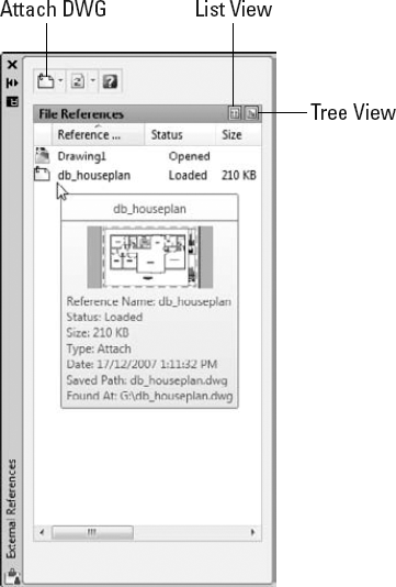
Click Attach DWG. (Click the down arrow if the tooltip offers to attach something else — see Figure 18-5.)
The Select Reference File dialog box appears.
Browse to find the file you want to attach, select it, and then click Open.
The External Reference dialog box appears.
Specify the parameters for the xref in the dialog box.
Parameters include the insertion point, scaling factors, and rotation angle. You can set these parameters in the dialog box or specify them on-screen, just as you can do when inserting a block, as described earlier in this chapter.
Note
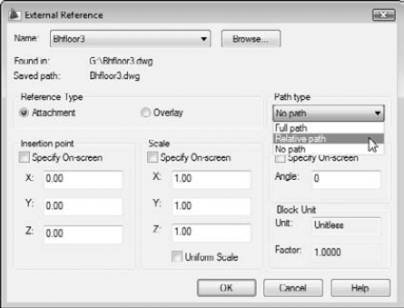
You can select the Attachment or Overlay radio button to tell AutoCAD how to handle the xref. The choice matters only if you create a drawing that uses xrefs, and then your drawing is, in turn, used as an xref. Attachment is the default choice, and it means that the xrefed file will always be included with your drawing when someone else uses your drawing as an xref. Overlay, the other choice, means that you see the xrefed drawing, but someone who xrefs your drawing won't see the overlaid file. By choosing Overlay, you can xref a map, for example, to your drawing of a house but not have the map show up when someone else xrefs your house drawing. (That person can xref the map, if need be.) I recommend that you use the default Attachment reference type unless you have a specific reason to do otherwise.
The Path Type drop-down list provides more flexibility in how the xref's path gets stored. See the "Forging an xref path" section, later in this chapter, for more information. For now, I recommend that you choose Relative Path instead of the default Full Path.
Click OK.
The externally referenced file appears in your drawing.
When you attach or overlay an xref, AutoCAD adds new layers to your current drawing that correspond to the layers in the xrefed DWG file. The new layers are assigned names that combine the drawing name and layer name; for example, if you xref the drawing MYSCREW.DWG, which has the layer names GEOMETRY, TEXT, and so on, the xrefed layers will be named MYSCREW|GEOMETRY, MYSCREW|TEXT, and so on. By creating separate layers corresponding to each layer in the xrefed file, AutoCAD eliminates the potential problem with blocks I warn you about in Chapter 17, when layers have the same name but different color or linetype in the two drawings.
To create a file that you can use as an external reference, just create a drawing and save it. That's it. You can then create or open another drawing and create an external reference to the previous one. The xrefed drawing appears in the host drawing as a single object, like a block insert. In other words, if you click any object in the xref, AutoCAD selects the entire xref. You can measure or object snap to the xrefed geometry, but you can't modify or delete individual objects in the xref — you open the xref drawing in order to edit its geometry.
AutoCAD's XOPEN command (not in AutoCAD LT) provides a quick way to open an xrefed drawing for editing. You just start the command and pick any object in the xref. Alternatively (and again, not in LT), you can select the xref in the External References palette and then right-click and choose Open to open one or more xrefs for editing. See the "Managing xrefs" section, later in this chapter, for more information.
When you attach an xref, AutoCAD, by default, stores the xref's full path — that is, the drive letter and sequence of folders and subfolders in which the DWG file resides — along with the filename. This default behavior corresponds to the Full Path setting in the Path Type drop-down list. (Figure 18-6 shows the three xref path options.) Full Path works fine as long as you never move files on your hard drive or network and never send your DWG files to anyone else — which is to say, it almost never works fine!
At the other end of the path spectrum, the No Path option causes AutoCAD not to store any path with the xref attachment — only the filename is stored. This is the easiest and best option if the host drawings and the xrefs reside in the same folder.
If you prefer to organize the DWG files for a particular project in more than one folder, then you'll appreciate AutoCAD's Relative Path option, shown in Figure 18-6. This option permits xrefing across more complex folder structures but avoids many of the problems that the Full Path option can cause. For example, you may have a host drawing, H:Project-XPlansFirst floor.dwg, that xrefs H:Project-XCommonColumn grid.dwg. If you choose Relative path, AutoCAD will store the xref path as .. CommonColumn grid.dwg instead of H:Project-XCommonColumn grid.dwg. Now if you decide to move the Project-X folder and its subfolders to a different drive (or send them to someone else who doesn't have an H: drive), AutoCAD will still be able to find the xrefs.
Note
When you use Relative Path, you'll see xref paths that include the special codes . and .. (single and double period). The single period means "this host drawing's folder," and the double period means "the folder above this host drawing's folder."
You can report on and change xref paths for a set of drawings with the AutoCAD Reference Manager (not in AutoCAD LT). See Chapter 19 for more information.
Tip
If all these path options and periods leave you feeling punchy, you can keep your life simple by always keeping host and xref drawings in the same folder and using the No Path option when you attach xrefs.
The External References palette includes many more options for managing xrefs after you attach them. Many of these options are hiding in right-click menus. Important options include
List of external references: You can change between the List view and Tree view of your drawing's external references just by clicking the appropriate button at the top of the palette (refer to Figure 18-5). You can resize the columns by dragging the column dividers or re-sort the list by clicking the column header names, just as in Windows Explorer.
Unload: Right-click an xref and choose Unload to make the selected xref disappear from the on-screen display of your drawing and from any plots you do of it, but retain the pointer and attachment information. Right-click again and choose Reload to redisplay an unloaded xref.
Reload: Right-click an xref and choose Reload to force AutoCAD to reread the selected xrefed DWG file from the disk and update your drawing with its latest contents. This feature is handy when you share xrefs on a network and someone has just made changes to a drawing that you've xrefed — especially for AutoCAD LT users who don't get automatic change notifications as in regular AutoCAD.
Detach: Right-click an xref in the External References palette and choose Detach to completely remove the selected reference to the external file from your drawing.
Bind: Right-click an xref and choose Bind to bring the selected xref into your drawing and turn it into a block. You might use this function, for example, to roll up a complex set of xrefs into a single archive drawing.
Warning
In many offices, binding xrefs without an acceptable reason for doing so is a crime as heinous as exploding blocks indiscriminately. In both cases, you're eliminating an important data management link. Find out what the policies are in your company. When in doubt, keep yourself out of a bind. And even when you do have a good reason to bind, you generally should do it on a copy of the host drawing.
Open: Right-click an xref and choose Open to open one or more xref drawings in separate drawing windows (I wish I didn't have to keep apologizing to you folks, but sorry LT users — you can't do that either). After you edit and save an xref drawing, return to the host drawing and use the Reload option in the External References palette to show the changes.
None of these options (other than opening and editing the xref) affects the xrefed drawing itself; it continues to exist as a separate DWG file. If you need to delete or move the DWG file that the xref refers to, do it in Windows Explorer.
Note
The fact that the xrefed drawing is a separate file is a potential source of problems when you send your drawing to someone else; that someone else needs all the files that your drawing depends on, or it will be useless. Make sure to include xrefed files in the package with your drawing. See Chapter 19 for a procedure.
AutoCAD (but not AutoCAD LT) includes an additional xref feature called xref clipping. You can use the XCLIP command to clip an externally referenced file or a block insertion so only part of it appears in the host drawing. AutoCAD LT doesn't include the XCLIP command, but if you open a drawing containing an xref that was clipped in AutoCAD, the clipped view will be preserved.
Blocks and xrefs are useful for organizing sets of drawings to use and update repeated elements. It's not always clear, though, when to use blocks and when to use xrefs. Applications for xrefs include
The parts of a title block that are the same on all sheets in a project.
Reference elements that need to appear in multiple drawings (for example, wall outlines, site topography, column grids).
Assemblies that are repeated in one or more drawings, especially if the assemblies are likely to change together (for example, repeated framing assemblies, bathroom layouts, modular furniture layouts).
Pasting up several drawings (for example, details or a couple of plans) onto one plot sheet.
Temporarily attaching a background drawing for reference or tracing.
On the other hand, blocks remain useful in simpler circumstances. Situations in which you might stick with a block are
Components that aren't likely to change.
Small components.
A simple assembly that's used repeatedly but in only one drawing. (You can easily update a block in one drawing with the REFEDIT command, or if you're using AutoCAD LT, by exploding the block, editing its components, and then redefining the block with the same name; for more on this procedure see Chapter 17.)
When you want to include attributes (variable text fields) that you can fill in each time you insert a block. Blocks let you include attribute definitions; xrefs don't. Refer to Chapter 17 for the lowdown on attributes.
Everyone in a company or workgroup should aim for consistency as to when and how they use blocks and xrefs. Check whether guidelines exist for using blocks and xrefs in your office. If so, follow them; if not, it would be a good idea to develop some guidelines.
AutoCAD includes three more xref-like features: the ability to attach raster images, DWF files, and DGN files to drawings. I cover DWF files in the next section and refer you to the online help if you should find some DGN files on your hands. The image feature is useful for adding a raster logo to a drawing title block or placing a photographed map or scene behind a drawing. A raster, or bitmapped, image is one that's stored as a field of tiny points.
Most AutoCAD drawings are vector files. A vector drawing is a graphic file defined by storing geometrical definitions of a bunch of objects. Typical objects include a line, defined by its two endpoints, and a circle, defined by its center point and radius. Vector-based images are typically smaller (in terms of the disk space they occupy) and more flexible than raster images but also are less capable of displaying visually rich images such as photographs.
Raster images often come from digital cameras or from other programs, such as Photoshop. Raster images also can come into the computer from some kind of scanner that imports a blueline print, photograph, or other image.
Whether you're doing your scanning yourself or having a service bureau do it for you, you need to know that AutoCAD handles most of the popular image file formats, including: the Windows BMP format; the popular Web graphics formats GIF and JPEG; common print formats like PCX, PNG, and TIFF; and the less popular DIB, FLC, FLI, GP4, MIL, RLE, RST, TGA, and several even more obscure ones.
Here are three scenarios in which you could incorporate raster images in your drawing:
Small stuff: You can add logos, special symbols, and other small images that you have in raster files.
Photographs and maps: You can add photographs (such as a future building site) and maps (for example, showing the project location).
Vectorization: To convert a raster image into a vector drawing by tracing lines in the raster image, you can attach the raster image in your drawing, trace the needed lines by using AutoCAD commands, and then detach the raster image. (This procedure is okay for a simple raster image; add-on software is available, from Autodesk and others, to support automatic or semiautomatic vectorization of more complex images.)
Using raster images is much like using external references. The raster image isn't stored with your drawing file; a reference to the raster image file is established from within your drawing, like an xref. You can clip the image and control its size, brightness, contrast, fade, and transparency. These controls fine-tune the appearance of the raster image on-screen and on a plot.
Note
When you attach raster images, you have to make sure that you send the raster files along when you send your drawing to someone else.
Follow these steps to bring a raster image into AutoCAD:
If the External References palette isn't already open, click External References on the Reference panel of the Blocks and References Ribbon (or choose Tools
Use the drop-down list on the first toolbar button to attach a drawing, an image, a DWF file, or a DGN file.
Click Attach Image and locate the image file you want to attach.
The Select Image File dialog box appears, as shown in Figure 18-7.
Browse to find the file you want to attach, select it, and then click Open.
Tip
Click the Details button in the Image dialog box to see more information about the resolution and image size of the image you're attaching.
Specify the parameters for the attached image in the dialog box.
Parameters include the insertion point, scale factor, and rotation angle. You can set these parameters in the dialog box or specify them on-screen, similar to what you can do with blocks and external references, as described earlier in this chapter.
The Image dialog box includes the same Full Path, Relative Path, and No Path options as those for attaching xrefs. (See the "Forging an xref path" section, earlier in this chapter.)
Click OK.
The image appears in your drawing.
If you need to ensure that the raster image floats behind other objects in the drawing, select the raster image, right-click, choose Draw Order, and then choose Send to Back.

You manage the images in your drawing with the External References palette. You can view a list of image files that appear in the current drawing, detach (remove) image references, and unload and reload images when needed. You can't bind an image to your drawing; it always remains an external file.
You can clip images so that only part of the image is displayed in your drawing. Choose Modify
Tip
Raster image files often are larger than DWG files of corresponding complexity; raster file size can affect performance within AutoCAD because the raster file loads into memory when you're working on your drawing. Some workarounds speed up operations:
Attach raster images late in the production process.
Create a lower-resolution version of the raster file, just large enough to create the desired effect in your drawing.
Right-click over an image in the External References palette and choose Unload to temporarily hide an image without losing the attachment information.
In addition, raster files can increase the time that AutoCAD takes to generate plots (and the plot file sizes) dramatically. Before you settle on using large raster files in your AutoCAD drawing, do some testing on zooming, editing, and plotting.
DWF stands for Design Web Format. You could think of a DWF as "DWG Lite" because it looks just like a drawing file and contains some of the actual drawing file data. I talk more about the web side of DWFs in Chapter 19; in this section I explain how you can use DWFs as reference files in your own drawings. (Some people call DWF files dwiffs, but I'm going to hold off on that one until I start hearing DWG files called dwiggs.)
You create DWFs from within AutoCAD in one of two ways. Either choose Plot and select the DWF option in the Printer/Plotter name list, or choose Publish and select DWF in the Publish To area of the Publish dialog box. DWFs are compact and secure: You can't edit a DWF in AutoCAD. The DWF format is ideal for two purposes: You can post DWFs on the Web, and you can send your drawings to consultants and clients in a form that they can't mess up. You can attach DWFs to your drawing files in pretty much the same way you attach drawings as external references. DWFs attached to drawing files are referred to as DWF underlays.
The previous sections show how to attach a DWG and a raster image. Follow these steps to attach a DWF file as an underlay:
If the External References palette isn't already open, click External References on the Reference panel of the Blocks and References Ribbon (or choose Tools
The toolbar at the top of the palette lets you attach an external file as an xref, a raster image file, or a DGN or DWF underlay. I cover attaching xrefs and images earlier in this chapter. See the online help for information on attaching DGN files.
Click Attach DWF and locate the file you want to attach.
The Select DWF File dialog box appears.
Browse to find the file you want to attach, select it, and then click Open.
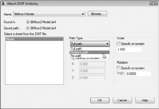
The Attach DWF Underlay dialog box appears.
Specify the parameters for the DWF in the dialog box.
The layout may be different, but the content is mostly the same. Parameters include specifying a sheet, the insertion point, scaling factors, rotation angle, and path type (see Figure 18-8). You can set these parameters in the dialog box or specify them on-screen, just as you can do when inserting a block, attaching an xref, or attaching an image, as described earlier in this chapter.
Click OK.
The externally referenced DWF file appears in your drawing.
Tip
DWF files aren't as precise as DWGs — that's why they're a lot smaller. When using object snap to locate points in DWFs, you may see the word approximate on the object snap tooltip. If this is a problem, you can increase the precision of your DWF file when you create it.