
We can easily go several hours without drinking water. We can comfortably go the better part of a day without eating food. But try and go more than a few minutes without breathing. (No, don’t really try.) Understanding the composition of the lower atmosphere—the troposphere—is among the most important environmental measurements we can take.
Everything floating around the troposphere—nitrogen, oxygen, carbon dioxide, water vapor, and all sorts of pollution—winds up in our lungs, on our plants, in our food, and in our water (see Figure 2-1). It dusts our windows, our automobiles, and our buildings. For this reason, the authors (as well as organizations like the American Lung Association) believe that it’s vitally important to know what’s inside every breath we take.
In the old days, when people wanted to know what was in the atmosphere, they used chemically-treated filter paper, and hung it in a breeze. The chemicals reacted with whatever was in the air and would respond by changing color. Or they bubbled the atmosphere through water and measured the different compounds that resulted as gas dissolved in water. This kind of work could only be performed in a dedicated chemistry lab.
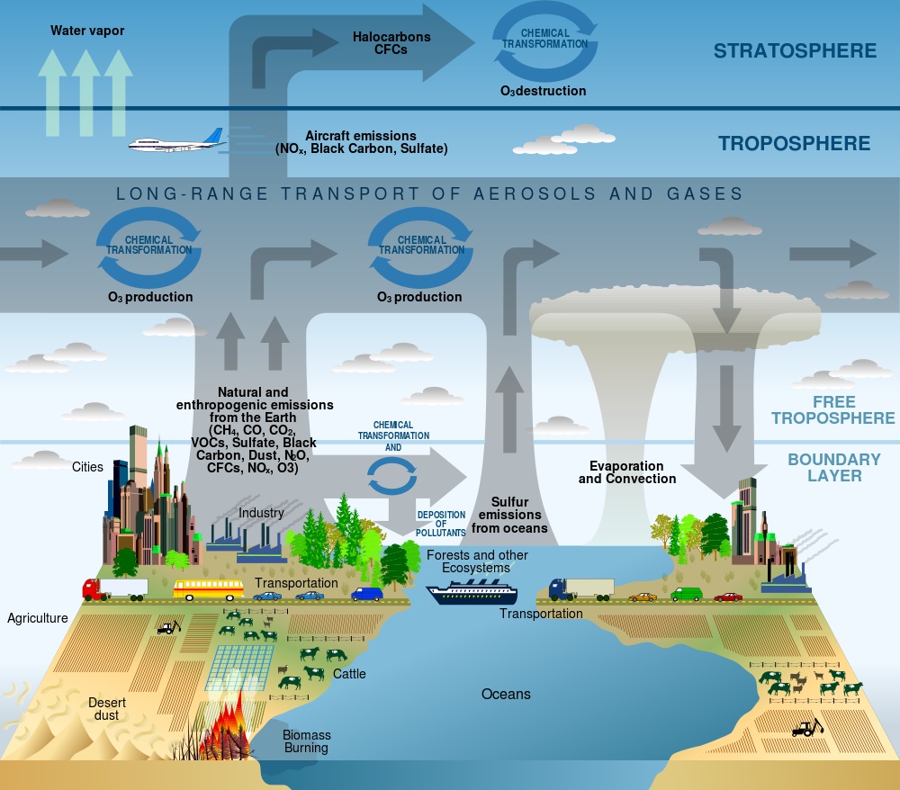
Figure 2-1. This illustration shows how different chemicals and other substances move into and through the troposphere. Credit: U.S. Climate Change Science Program, 2003.
Fortunately for us, we can now purchase a small, complete atmospheric laboratory for less than $10, in the form of an electronic gas sensor (Figure 2-2). These sensors detect different substances in the atmosphere by measuring the changing resistance of a film made of tin dioxide.

Figure 2-2. There are lots of inexpensive sensors on the market that can be used for DIY monitoring.
Oxygen in the atmosphere removes electrons from the tin dioxide film, which decreases its conductivity (and increases its resistance). When other types of gases, particularly those that are chemically reducing, touch the tin dioxide film, electrons are injected into the material. This increases the conductivity (and lowers the resistance) of the tin dioxide layer. You can use your Arduino to measure that change in resistance.
It’s important to keep in mind that tin dioxide sensors tend to be broadly selective. While certain sensors may be marketed as being "alcohol" sensors or "carbon monoxide" sensors, they actually respond to more than just alcohol or carbon monoxide, respectively; they respond to a wide family of similar gases. Manufacturers can make the tin dioxide-based gas sensors more selective by adding various catalysts into the sensor head, or by using external filters. The datasheet provided with each sensor explains more completely how to adjust the sensitivity of each sensor for various gases.
There are electronic sensors for a wide range of gases. As we write this book in the summer of 2012, there are easy-to-use inexpensive sensors on the market to detect carbon monoxide, carbon dioxide, liquid petroleum gas, butane, propane, methane (natural gas), hydrogen, ethyl alcohol, benzene, volatile organic compounds, ammonia, ozone, hydrogen sulfide, and more. It’s not unreasonable to expect that it won’t be long before cheap sensors hit the market that can detect nitrogen oxides and other contaminants. All of these gases count as pollutants; in varying concentrations, all of them can be harmful.
We’re going to use the MQ-2 and MQ-6 sensors from Hanwei, Inc. in this gadget. Both detect combustible gases: the MQ-6 detects butane and liquefied petroleum gas (LPG), also called propane (both hydrocarbons), while the MQ-2 is sensitive to LPG, methane (the primary component of natural gas, and a potent greenhouse gas), and smoke. We feel that both sensors together are a great way to start measuring ground-level air pollution.
A heating element in the electronic circuit heats the metal, making it more reactive with atmospheric gases. As the various gases react with the metal, the resistance changes in proportion to the amount of that gas present in the air exposed to the sensor. This change in resistance is measured by the Arduino analog port. That’s basically it.
If we plug the heater directly into Arduino, we find ourselves with a problem. The heater consumes 800 mW, which works out to equal 200 mA (.8 W / 5 V = .2 A). A standard Arduino pin can only reliably source 20 mA (in other words, only about 10% of the power the heater needs). We have correspondence from the manufacturers indicating that the heater can be powered by connecting it to the +5 V Arduino pin, but frankly, we’re skeptical. We’ve got to come up with a way to use Arduino to control the amount of power that goes to the heating units, so that the heating unit is not on constantly, without actually having Arduino provide that power.
Both these problems—providing power to the heater and controlling that power—have a single solution, probably the greatest invention of the 20th century: the transistor.
Transistors are used to amplify electronic signals cheaply and efficiently, with very little noise, while giving off very little heat (Figure 2-3). Transistors also act as tiny, efficient digital switches. Since all computer activity breaks down into a series of binary "on and off" states represented by 1s and 0s, transistors by the millions, embedded into a silicon chip, control those on and off signals.
We really can’t overstate the importance of the transistor. We don’t have room in this book to discuss the details of how transistors work; suffice it to say that the lightweight, cheap electronic gadgets in our lives—handheld cell phones, computers, digital cameras, flat screen TVs, microwave ovens, cable television, touchtone phones, simple portable AM/FM radios, essentially anything more complicated than a flashlight—would be impossible without the transistor.

The first thing you notice when you look at a transistor is that unlike almost every other electronic device we’ve seen so far, a transistor has three terminals. We can control the voltage between two of the terminals by applying a specific electric current or voltage to the third terminal. The three terminals are the base, the collector, and the emitter. The base is the controller; voltage applied here determines whether or not electricity flows from the collector to the emitter. The collector is the "source" of the electrical current, and the emitter is the output.
If we were to send varying levels of current from the base, we can regulate the amount of current flowing from the collector to the emitter. This is how a transistor acts as an amplifier: a very low signal coming into the base is repeated at a much larger voltage provided by the collector.
When we use a transistor as a switch, the circuitry is even simpler. A transistor switch is either fully on or fully off. A small data signal to the base determines whether the transistor is switched on or off. When it is switched on, current flows between the ground and the collector. This simple setup lets us use Arduino to turn on components that have a separate power supply.
| Amount | Part Type | Properties/(Assembly Code) |
|---|---|---|
2 | 1 k Ω resistor | Package THT; tolerance 5%; bands 4; resistance 1 k Ω; pin spacing 400 mil (R1 & R2) |
1 | Voltage regulator, 5 V | Package TO220 [THT]; voltage 5 V (U1) |
2 | NPN-transistor | Package TO92 [THT]; type NPN (Q1 & Q2) |
1 | Arduino UNO R3 | (Arduino1) |
1 | LCD screen | Character type, 16 pins (LCD1) |
1 | Battery block 9 V | (VCC1) |
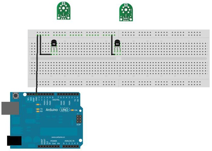
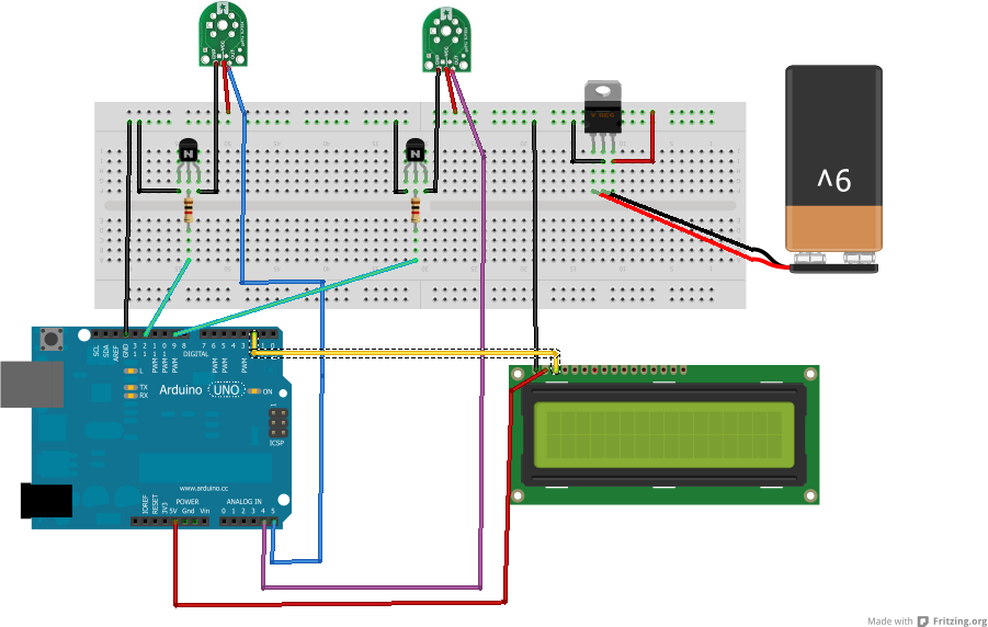
- Connect a wire from the GND pin of Arduino to the GND rail of the breadboard. Connect the GND rail of the breadboard to the EMITTER pin of the transistor (Figure 2-4).
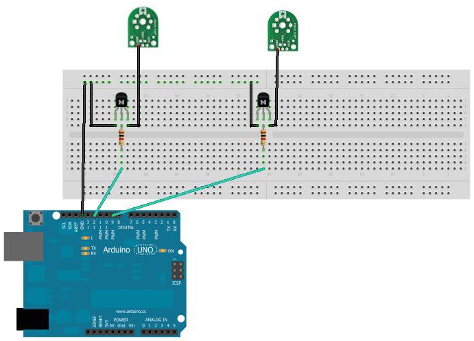
- Connect the BASE pin of the transistor to a 1 K resistor, and connect the resistor to an Arduino digital pin (Figure 2-5).

- Connect the COLLECTOR pin of the transistor to the GND pin of the sensor (Figure 2-6).
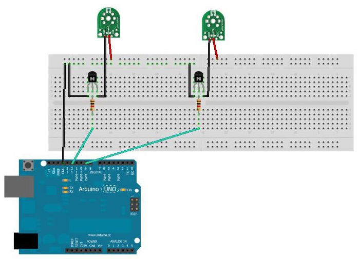
- Connect the +5 (VCC) sensor pins to the breadboard’s power rail (Figure 2-7). Don’t worry; we’re going to add a power supply later.
- Connect the data lines from the sensors to Arduino analog ports 4 and 5 (Figure 2-8).

- Connect the 7805 +5 VDC voltage regulator. This regulates the voltage coming from your independent power source for the sensor heaters. Like the transistor, the voltage regulator also has three terminals: a center pin goes to GND, the pin on the left is input, and the pin on the right is output (Figure 2-9).

- Connect the GND pin to the GND rail of the breadboard AND to the black (or –) wire on your power supply. Connect the input pin to the red (or +) wire on your power supply. Connect the output pin to the power rail on the breadboard (Figure 2-10).
This device takes an input current (up to 35 volts), and changes it to a stable, fixed +5 VDC. In our example, we’re using a standard 9 volt battery at the current source, but you can use just about anything: a 6 volt lantern battery, two 3.7 volt lithium polymer batteries connected in series, even a bunch of AA batteries. The total capacity of your power source should be your main determining factor: smaller batteries generally provide fewer amp-hours, meaning that the lifespan of your gadget can be cut short if you run out of power.
Don’t connect the battery until you actually need it, or add an ON-OFF switch to power it up when you’re ready to start taking readings.
Note
Optionally, connect the LCD. The data line is Arduino pin 2, ground goes to GND, and the power supply is Arduino’s 3.3 V pin.
You can find this sketch in the AMWA GitHub repository.
#include <SoftwareSerial.h>
#include <SD.h>
#include <EEPROM.h>
#include<stdlib.h>

// Liquid Crystal Display
// Define the LCD pins: We'll be using a serial-based LCD display
// which only required +3.3Volts, GND, and a single data line.
// databuff and displaybuff hold the data to be displayed
#define LCDIn 2
#define LCDOut 5
SoftwareSerial mySerialPort(LCDIn, LCDOut);


// Data Buffers for the LCD
char databuff1[16];
char databuff2[16];
char dispbuff[16];

// GAS SENSORS
// Analog input pin that reads the first gas sensor
const int gasPin1 = A5;

// Analog input pin that reads the gas sensor
const int gasPin2 = A4;

// The digital pin that controls the heater of gas sensor 1
const int heaterPin1 = 7;

// The digital pin that controls the heater of gas sensor 2
const int heaterPin2 = 9;

// LED connected to digital pin 13
const int ledPin = 13;

// value read from the sensor A5
int gasVal1 = 0;

// value read from the sensor A4
int gasVal2 = 0;

long warmup = 180000;           // enter time for heaters to warmup, in milliseconds.
// 180,000 milliseconds = 3 minutes

long downtime = 360000;       // enter delay between readings, in milliseconds.
// 360,000 milli seconds = 6 minutes

//EEPROM records require two bytes to store a 1024 bit value.
//Each gas sensor returns a value from 0-1024, taking 2 bytes.
//To store gas sensor data would require a record index,
//plus two bytes for the first gas sensor, two bytes for the second gas sensor
//For a total of five bytes per record.

// current EEPROM address
int addr =0;

//EEPROM record number
int record = 0;

//EEPROM record length
int reclen = 5;

//switch to tell if an SD card is present
int SDPresent = 1;

void setup()
{
  // initialize serial communications at 9600 bps:
  Serial.begin(9600);

  pinMode(heaterPin1, OUTPUT);  // sets the digital pins as output
  pinMode(heaterPin2, OUTPUT);
  pinMode(LCDOut, OUTPUT);

  //reset the LCD
  mySerialPort.begin(9600);
  mySerialPort.write(0xFE);
  mySerialPort.write(0x01);
  sprintf(databuff1,"Wakeup Test");
  sprintf(dispbuff,"%-16s",databuff1);
  mySerialPort.print(dispbuff);

  // Set up SD card, let us know if SD card is absent
  pinMode(10, OUTPUT);
  if (!SD.begin(4))
  {
    SDPresent =0;
    sprintf(databuff2,"NO SD CARD!!!");
    sprintf(dispbuff,"%-16s",databuff2);
    mySerialPort.print(dispbuff);
    Serial.println("NO SD CARD!!!");
    delay(6000);
  }
  delay(3333);
}

void loop()
{
  long scratch=0;   // scratch variable

  // set the timer
  unsigned long counter = millis();

  //turn first heater on
  digitalWrite(heaterPin1, HIGH);

  // wait 3 minutes for heater to heat up
  while(millis() < (counter + warmup))
  {
    sprintf(databuff1,"Unit1 Activated");
    sprintf(dispbuff,"%-16s",databuff1);
    mySerialPort.print(dispbuff);

    scratch = (int)((counter+warmup - millis())/1000);
    sprintf(databuff2,"Countdown: %3d", scratch);
    sprintf(dispbuff,"%-16s",databuff2);
    mySerialPort.print(dispbuff);

    Serial.println(scratch);
  }

  // read the analog in value:
  gasVal1 = analogRead(gasPin1);
  sprintf(databuff1,"read unit 1");
  sprintf(dispbuff,"%-16s",databuff1);
  mySerialPort.print(dispbuff);

  // shut off the first heater
  digitalWrite(heaterPin1, LOW);

  //turn second heater on
  digitalWrite(heaterPin2, HIGH);
  sprintf(databuff2,"turning on unit2");
  sprintf(dispbuff,"%-16s",databuff2);
  mySerialPort.print(dispbuff);

  // wait 3 minutes for heater to heat up
  while(millis() < (counter + warmup + warmup))
  {
    sprintf(databuff1,"Unit2 Activated");
    sprintf(dispbuff,"%-16s",databuff1);
    mySerialPort.print(dispbuff);

    scratch = (int)((counter+warmup+warmup - millis())/1000);
    sprintf(databuff2,"Countdown: %3d", scratch);
    sprintf(dispbuff,"%-16s",databuff2);
    mySerialPort.print(dispbuff);

    Serial.println(scratch);
  }

  // read the analog in value:
  gasVal2 = analogRead(gasPin2);
  sprintf(databuff2,"reading unit2");
  sprintf(dispbuff,"%-16s",databuff2);
  mySerialPort.print(dispbuff);

  // shut off the second heater
  digitalWrite(heaterPin2, LOW);

  //Display on LCD
  sprintf(databuff1,"Gas1:%4d",gasVal1);
  sprintf(dispbuff,"%-16s",databuff1);
  mySerialPort.print(dispbuff);
  sprintf(databuff2,"Gas2:%4d",gasVal2);
  sprintf(dispbuff,"%-16s",databuff2);
  mySerialPort.print(dispbuff);

//write to SD card
  if(SDPresent = 1)
  {
    writeDataToSD(databuff1, databuff2);
  }

  //Wait downtime and start again
  //to make more frequent measurements, change value of downtime
  while(millis() < (counter +downtime))
  {
  }
}

void writeDataToSD(String dataString1, String dataString2)
{
  // open the file. note that only one file can be open at a time,
  // so you have to close this one before opening another.
  File dataFile = SD.open("datalog.txt", FILE_WRITE);

  // if the file is available, write to it:
  if (dataFile)
  {
    Serial.println("Hooray, we have a file!");
    dataFile.print(millis());
    dataFile.print(",");
    dataFile.print(dataString1);
    dataFile.print(",");
    dataFile.println(dataString2);

    dataFile.close();

    // print to the serial port too:
    Serial.print(millis());
    Serial.print(",");
    Serial.print(dataString1);
    Serial.print(",");
    Serial.println(dataString2);

    //Print to LCD
    mySerialPort.print("Datafile written");
  }
}You can connect Arduino to components that display data, as well as those that store data for later use.
Liquid crystal displays (LCDs) are cheap and easy ways to display data, status, warnings, and other messages from Arduino. They come in many different colors: you can buy LCDs with amber characters on a black background, black characters on a green background, yellow characters on a blue background, and other color combinations. Some LCDs have two rows of 16 characters, others four rows of 20 characters, and other display combinations are available as well. But for our uses, the biggest differences in LCDs involve the way they handle data.
The most basic (and least expensive) LCDs make you do all the data handling. They can take up as many as 10 digital data pins (most Arduinos only have 13), and might even require you to design your own characters. Some makers love doing stuff like that, but others just want to plug in a device and have it work.
For our uses, we’ve decided to go with a serial-controlled LCD, one in which a small microprocessor attached to the LCD takes care of all the data and character management. It’s more expensive, but also much easier to use. All we need to do is ground the device, give it some power, and feed it data.
Step seven of the build explains how to connect the LCD to the tropospheric gas detector.
You might have noticed in the code that Arduino writes the data it recieves to something called EEPROM. This stands for "Electrically Erasable Programmable Read-Only Memory." This is a type of computer memory that is nonvolatile; it remains in place after Arduino is powered down, or after a new program is loaded. EEPROM is perfect for storing data that has to last a long time (a long time by Arduino standards, that is), such as months or years. Our gadget uses 5 bytes of EEPROM to store a single observation record: 1 byte for the record number, and 2 bytes apiece for each sensor’s data.
We’ve included a small program to extract tropospheric gas data from the Arduino’s EEPROM. Simply connect your Arduino to your computer via the USB cable, upload the following sketch, and then view the serial monitor.
#include <EEPROM.h>

// start reading from the first byte (address 0) of the EEPROM

int address = 1;
int record = 0;
unsigned int Sensor1 = 0;
unsigned int Sensor2 = 0;

int q;
int m;

void setup()
{
  Serial.begin(9600);
  Serial.println("Record#, Sensor1, Sensor2");
  for(int i =0; i<=95; i++)
  {
    readData();
  }
}

void loop()
{
  // There's no need for this program to loop.  We know what we want to do,
  // and we just did it in setup().
}

void readData()
{
  record = EEPROM.read(address++);
  Serial.print(record);
  Serial.print(",");
  q = EEPROM.read(address++);
  delay(20);
  m = EEPROM.read(address++);
  delay(20);
  Sensor1 = (q*256)+m;

  Serial.print(Sensor1);
  Serial.print(",");
  q = EEPROM.read(address++);
  delay(20);
  m = EEPROM.read(address++);
  delay(20);
  Sensor2 = (q*256)+m;

  Serial.print(Sensor2);
  Serial.print(",");
  q = EEPROM.read(address++);
  delay(20);
  m = EEPROM.read(address++);
  delay(20);

 }
The result is a CSV display of your data, ready to be copied and pasted into your favorite spreadsheet program.
If you are storing your gas detector data on the SD card, you’ll find a file called DATALOG.TXT. That file contains your measurements in CSV (comma separated value) format. To save space on Arduino, we did not massage the data in any way. You can open this file in your favorite spreadsheet program and work with it as desired.
Of course, there’s not just one way to build a gas detector. There are many different configurations you can try (such as more or different sensors) that will provide more detailed data, but what changes (if any) will you have to make to the circuit to be sure it works properly? Will you need to beef up the batteries, or try a totally new power source? Here are some other ideas to make your gas detector more versatile.
Does hot humid air hold more pollution than cold dry air? If you add a temperature/humidity sensor to the gadget, can you detect any correlations between temperature/humidity and toxic gas concentration?
As we noted earlier, Hanwei and other manufacturers offer many different gas sensors, often (but not always) built around the same basic circuitry, making it relatively easy to add more sensors to a gadget, or swap new sensors for old ones. It might be interesting to add an MQ-131 ozone sensor to the MQ-2 and MQ-6 sensors—is there a correlation between automobile pollution and ozone? between temperature/humidity and ozone?
One drawback to the current gadget is the batteries last only a few days. Is it possible to have the gadget work forever by powering it with the sun?
Yes, with some caveats. The heating elements of the gas sensors are real power hogs, and running this device totally on solar power might or might not be practical depending on the size of the solar panel, the amount of sunlight at your location, and the number of gas sensors you have. If you want to give it a try, we’d recommend starting with something like the Adafruit USB/SOLAR LiPoly charger. This device will handle all the power management for you.
The key question is the size of the solar panel: if you calculate the amount of power your Arduino and sensors use, and compare it to the net power you can expect from the solar panel/charger (taking into account your location and time of year), you can get a good idea if solar will work for your gadget.
Wouldn’t it be great if, instead of having to fetch data from your gadget, you could make your gadget send you its data? You can, with a GSM module. This device, available from all the usual suppliers like Sparkfun and Adafruit, is essentially the guts of a cell phone without the keypad, display, speaker, microphone, or ringtones. By connecting it in place of (or along with) the LCD display, you can have your gadget send you text messages (or even post on Twitter!) its latest findings. You’ll need to get a separate SIM card with a data plan, but these usually cost in the range of $5 to $10 per month.
Now we come to the strangest part of this book: the warning not to leave your gas detector unattended, anywhere, ever. Here’s why:
In May 2012, Takeshi Miyakawa, a visual artist and furniture designer in New York City, placed a portable battery-powered light inside a translucent "I Love NY" plastic shopping bag, and hung it from a metal rod attached to a tree. When the lamp was on, the bag glowed from within. A friend of the artist said he did this "to lift people’s spirits. He was simply trying to say that he loves the city and spread that attitude around."
Unfortunately for Miyakawa, someone in the neighborhood saw a contraption with wires, batteries, and plastic boxes and called the New York Police Department’s bomb squad, which evacuated the area and took two hours to determine that a battery and a light was just a battery and a light. When the police tracked the device to Miyakawa, they arrested him and charged him with two counts of first-degree reckless endangerment, two counts of placing a false bomb or hazardous substance in the first degree, two counts of placing a false bomb or hazardous substance in the second degree, two counts of second-degree reckless endangerment, and two counts of second-degree criminal nuisance. A judge ordered him sent to Bellevue hospital for psychiatric evaluation, as well.
All for hanging a light in a tree.
Miyakawa’s experience is not unique, unfortunately. In another case, researchers from Carnegie-Mellon University built similar detectors to ours, and placed them at various points around the Pittsburgh area. While the sensors were enclosed in professionally made plastic cases, and were clearly labeled as an approved research project, once again the police bomb squad was called. (The students didn’t report being arrested. However, they did say it took a great deal of negotiation with the authorities to get their equipment back.)
The US Department of Homeland Security (DHS) urges people to "be vigilant, take notice of your surroundings, and report suspicious items or activities to local authorities immediately." As a result, homemade electronic gadgets that once upon a time (at least, in the lifetimes of the authors) might have been regarded as interesting curiosities are now treated as threats. Many people don’t understand hobby electronics, and are frightened by what they do not understand. Police believe they must treat every suspicious package as if it may be harmful.
The point of telling you all this is not to scare you from building monitoring devices, but to warn you that a home-built, Arduino-based gas sensor might, to the unknowing eye, look like a box of batteries and wires and a scary thing with blinking lights. Leaving something like this unattended, without permission, on property you don’t own, can get you into a world of trouble.
The following subsections are a couple ideas for solving this problem.
Look into official channels through which you can deploy experimental packages in public. At A.M.W.A. World Headquarters in New York City, we looked to the Parks Department, which allows researchers to leave experimental devices in some of the city’s parks. The entire application process is on the city’s website. It’s fairly extensive, requiring an explanation of the experiment and a description of the device, but can be filled out in a single sitting.
Unfortunately, processing these permits seems to take a long time. We applied for one in early May 2012, and it still hadn’t arrived by the time this book went to press in November.
- If you’re a student, get your teachers on your side when it comes to your projects. Arduino is so new that there’s a good chance you’ll be teaching the teachers for a change, and once your teachers understand what you’re doing, they’ll be among your staunchest supporters.
- If you’re a member of a hackerspace, have an open house. Invite members of the community to meet you in person and learn about what you’re doing. This may work wonders toward alleviating some of the public’s fear of DIY electronics.
- If you’re not a member of a hackerspace, consider joining one, or even starting one. Good online resources for finding and learning more about hackerspaces are the Hackerspace Wiki and the UK Hackspace Foundation.