
16 Designing for fault tolerance
- What fault-tolerance is and why you need it
- Using redundancy to remove single points of failure
- Improving fault tolerance by retrying on failure
- Using idempotent operations to retry on failure
- AWS service guarantees
Failure is inevitable: hard disks, networks, power, and so on all fail from time to time. But failures do not have to affect the users of your system.
A fault-tolerant system provides the highest quality to your users. No matter what happens in your system, the user is never affected and can continue to go about their work, consume entertaining content, buy goods and services, or have conversations with friends. A few years ago, achieving fault tolerance was expensive and complicated, but with AWS, providing fault-tolerant systems is becoming an affordable standard. Nevertheless, building fault-tolerant systems is the top tier of cloud computing and might be challenging at the beginning.
Designing for fault tolerance means building for failure and building systems capable of resolving failure conditions automatically. An important aspect is avoiding single points of failures. You can achieve fault tolerance by introducing redundancy into your system. Instead of running your application on a single EC2 instance, you distribute the application among multiple machines. Also, decoupling the parts of your architecture such that one component does not rely on the uptime of the others is important. For example, the web server could deliver cached content if the database is not reachable.
The services provided by AWS offer different types of failure resilience. Resilience is the ability to deal with a failure with no or little effect on the user. You will learn about the resilience guarantees of major services in this chapter. But, in general, if you are unsure about the resilience capabilities of an AWS service, refer to the Resilience section of the official documentation for that service. A fault-tolerant system is very resilient to failure. We group AWS services into the following three categories:
-
No guarantees (single point of failure)—No requests are served if failure occurs.
-
High availability—In the case of failure, recovery can take some time. Requests might be interrupted.
-
Fault tolerant—In the case of failure, requests are served as before without any availability problems.
The most convenient way to make your system fault tolerant is to build the architecture using only fault-tolerant services, which you will learn about in this chapter. If all your building blocks are fault tolerant, the whole system will be fault tolerant as well. Luckily, many AWS services are fault tolerant by default. If possible, use them. Otherwise, you’ll need to deal with the consequences and handle failures yourself.
Unfortunately, one important service isn’t fault tolerant by default: EC2 instances. Virtual machines aren’t fault tolerant. This means an architecture that uses EC2 isn’t fault tolerant by default. But AWS provides the building blocks to help you improve the fault tolerance of virtual machines. In this chapter, we will show you how to use Auto Scaling groups, Elastic Load Balancing (ELB), and Simple Queue Service (SQS) to turn EC2 instances into fault-tolerant systems.
First, however, let’s look at the level of failure resistance of key services. Knowing which services are fault tolerant, which are highly available, and which are neither will help you create the kind of fault tolerance your system needs.
The following services provided by AWS are neither highly available nor fault tolerant. When using one of these services in your architecture, you are adding a single point of failure (SPOF) to your infrastructure. In this case, to achieve fault tolerance, you need to plan and build for failure as discussed during the rest of the chapter:
-
Amazon Elastic Compute Cloud (EC2) instance—A single EC2 instance can fail for many reasons: hardware failure, network problems, availability zone (AZ) outage, and so on. To achieve high availability or fault tolerance, use Auto Scaling groups to set up a fleet of EC2 instances that serve requests in a redundant way.
-
Amazon Relational Database Service (RDS) single instance—A single RDS instance could fail for the same reasons that an EC2 instance might fail. Use Multi-AZ mode to achieve high availability.
All the following services are highly available (HA) by default. When a failure occurs, the services will suffer from a short downtime but will recover automatically:
-
Elastic Network Interface (ENI)—A network interface is bound to an AZ, so if this AZ goes down, your network interface will be unavailable as well. You can attach an ENI to another virtual machine in case of a smaller outage, however.
-
Amazon Virtual Private Cloud (VPC) subnet—A VPC subnet is bound to an AZ, so if this AZ suffers from an outage, your subnet will not be reachable as well. Use multiple subnets in different AZs to remove the dependency on a single AZ.
-
Amazon Elastic Block Store (EBS) volume—An EBS volume distributes data among multiple storage systems within an AZ. But if the whole AZ fails, your volume will be unavailable (you won’t lose your data, though). You can create EBS snapshots from time to time so you can re-create an EBS volume in another AZ.
-
Amazon Relational Database Service (RDS) Multi-AZ instance—When running in Multi-AZ mode, a short downtime (one minute) is expected if a problem occurs with the master instance while changing DNS records to switch to the standby instance.
The following services are fault tolerant by default. As a consumer of the service, you won’t notice any failures:
-
Amazon Virtual Private Cloud (VPC) with an ACL and a route table
-
AWS Identity and Access Management (IAM, not bound to a single region; if you create an IAM user, that user is available in all regions)
In this chapter, you’ll learn everything you need to design a fault-tolerant web application based on EC2 instances (which aren’t fault tolerant by default). During this chapter, you will build a fault-tolerant web application that allows a user to upload an image, apply a sepia filter to the image, and download the image. First, you will learn how to distribute a workload among multiple EC2 instances. Instead of running a single virtual machine, you will spin up multiple machines in different data centers, also known as availability zones. Next, you will learn how to increase the resilience of your code. Afterward, you will create an infrastructure consisting of a queue (SQS), a load balancer (ALB), EC2 instances managed by Auto Scaling groups, and a database (DynamoDB).
16.1 Using redundant EC2 instances to increase availability
Here are just a few reasons your virtual machine might fail:
-
If the host hardware fails, it can no longer host the virtual machine on top of it.
-
If the network connection to/from the host is interrupted, the virtual machine will lose the ability to communicate over the network.
-
If the host system is disconnected from the power supply, the virtual machine will fail as well.
Additionally, the software running inside your virtual machine may also cause a crash for the following reasons:
-
If your application contains a memory leak, the EC2 instance will run out of memory and fail. It may take a day, a month, a year, or more, but eventually it will happen.
-
If your application writes to disk and never deletes its data, the EC2 instance will run out of disk space sooner or later, causing your application to fail.
-
Your application may not handle edge cases properly and may instead crash unexpectedly.
Regardless of whether the host system or your application is the cause of a failure, a single EC2 instance is a single point of failure. If you rely on a single EC2 instance, your system will fail up eventually. It’s merely a matter of time.
16.1.1 Redundancy can remove a single point of failure
Imagine a production line that makes fluffy cloud pies. Producing a fluffy cloud pie requires the following production steps (simplified!):
The current setup is a single production line. The big problem with this process is that whenever one of the steps crashes, the entire production line must be stopped. Figure 16.1 illustrates what happens when the second step (cooling the pie crust) crashes. The steps that follow no longer work, because they no longer receive cool pie crusts.

Why not have multiple production lines, each producing pies from pie crust through packaging? Instead of one line, suppose we have three. If one of the lines fails, the other two can still produce fluffy cloud pies for all the hungry customers in the world. Figure 16.2 shows the improvements; the only downside is that we need three times as many machines.

The example can be transferred to EC2 instances. Instead of having only one EC2 instance running your application, you can have three. If one of those instances fails, the other two will still be able to serve incoming requests. You can also minimize the cost of one versus three instances: instead of one large EC2 instance, you can choose three small ones. The problem that arises when using multiple virtual machines: how can the client communicate with the instances? The answer is decoupling: put a load balancer or message queue between your EC2 instances and the client. Read on to learn how this works.
16.1.2 Redundancy requires decoupling
In chapter 14, you learned how to use Elastic Load Balancing (ELB) and the Simple Queue Service (SQS) to decouple different parts of a system. You will apply both approaches to build a fault-tolerant system next.
First, figure 16.3 shows how EC2 instances can be made fault tolerant by using redundancy and synchronous decoupling. If one of the EC2 instances crashes, the load balancer stops routing requests to the crashed instances. Then, the Auto Scaling group replaces the crashed EC2 instance within minutes, and the load balancer begins to route requests to the new instance.

Take a second look at figure 16.3 and see what parts are redundant:
-
Availability zones (AZs)—Two are used. If one AZ suffers from an outage, we still have instances running in the other AZ.
-
Subnets—A subnet is tightly coupled to an AZ. Therefore, we need one subnet in each AZ.
-
EC2 instances—Two subnets with one or more EC2 instances lead to redundancy among availability zones.
-
Load Balancer—The load balancer spans multiple subnets and, therefore, multiple availability zones.
Next, figure 16.4 shows a fault-tolerant system built with EC2 that uses the power of redundancy and asynchronous decoupling to process messages from an SQS queue.

Second, in figures 16.3 and 16.4, the load balancer and the SQS queue appear only once. This doesn’t mean that ELB or SQS are single points of failure; on the contrary, ELB and SQS are both fault tolerant by default.
You will learn how to use both models—synchronous decoupling with a load balancer and asynchronous decoupling with a queue—to build a fault-tolerant system in the following sections. But before we do so, let’s have a look into some important considerations for making your code more resilient.
16.2 Considerations for making your code fault tolerant
If you want to achieve fault tolerance, you have to build your application accordingly. You can design fault tolerance into your application by following two suggestions:
16.2.1 Let it crash, but also retry
The Erlang programming language is famous for the concept of “let it crash.” That means whenever the program doesn’t know what to do, it crashes, and someone needs to deal with the crash. Most often people overlook the fact that Erlang is also famous for retrying. Letting it crash without retrying isn’t useful—if you can’t recover from a crash, your system will be down, which is the opposite of what you want.
You can apply the “let it crash” concept (some people call it “fail fast”) to synchronous and asynchronous decoupled scenarios. In a synchronous decoupled scenario, the sender of a request must implement the retry logic. If no response is returned within a certain amount of time, or an error is returned, the sender retries by sending the same request again. In an asynchronous decoupled scenario, things are easier. If a message is consumed but not acknowledged within a certain amount of time, it goes back to the queue. The next consumer then grabs the message and processes it again. Retrying is built into asynchronous systems by default.
“Let it crash” isn’t useful in all situations. If the program wants to respond to the sender but the request contains invalid content, this isn’t a reason for letting the server crash: the result will stay the same no matter how often you retry. But if the server can’t reach the database, it makes a lot of sense to retry. Within a few seconds, the database may be available again and able to successfully process the retried request.
Retrying isn’t that easy. Imagine that you want to retry the creation of a blog post. With every retry, a new entry in the database is created, containing the same data as before. You end up with many duplicates in the database. Preventing this involves a powerful concept that’s introduced next: idempotent retry.
16.2.2 Idempotent retry makes fault tolerance possible
How can you prevent a blog post from being added to the database multiple times because of a retry? A naive approach would be to use the title as the primary key. If the primary key is already used, you can assume that the post is already in the database and skip the step of inserting it into the database. Now the insertion of blog posts is idempotent, which means no matter how often a certain action is applied, the outcome must be the same. In the current example, the outcome is a database entry.
It continues with a more complicated example. Inserting a blog post is more complicated in reality, because the process might look something like this:
Let’s take a close look at each step.
1. Create a blog post entry in the database
We covered this step earlier by using the title as a primary key. But this time, we use a universally unique identifier (UUID) instead of the title as the primary key. A UUID like 550e8400-e29b-11d4-a716-446655440000 is a random ID that’s generated by the client. Because of the nature of a UUID, it’s unlikely that two identical UUIDs will be generated. If the client wants to create a blog post, it must send a request to the load balancer containing the UUID, title, and text. The load balancer routes the request to one of the backend servers. The backend server checks whether the primary key already exists. If not, a new record is added to the database. If it exists, the insertion continues. Figure 16.5 shows the flow.

Figure 16.5 Idempotent database insert: Creating a blog post entry in the database only if it doesn’t already exist
Creating a blog post is a good example of an idempotent operation that is guaranteed by code. You can also use your database to handle this problem. Just send an insert to your database. The next three things could happen:
-
Your database inserts the data. The operation is successfully completed.
-
Your database responds with an error because the primary key is already in use. The operation is successfully completed.
-
Your database responds with a different error. The operation crashes.
Think twice about the best way to implement idempotence!
This step sends an invalidation message to a caching layer. You don’t need to worry about idempotence too much here: it doesn’t hurt if the cache is invalidated more often than needed. If the cache is invalidated, then the next time a request hits the cache, the cache won’t contain data, and the original source (in this case, the database) will be queried for the result. The result is then put in the cache for subsequent requests. If you invalidate the cache multiple times because of a retry, the worst thing that can happen is that you may need to make a few more calls to your database. That’s easy.
3. Post to the blog’s Twitter feed
To make this step idempotent, you need to use some tricks, because you interact with a third party that doesn’t support idempotent operations. Unfortunately, no solution will guarantee that you post exactly one status update to Twitter. You can guarantee the creation of at least one (one or more than one) status update or at most one (one or none) status update. An easy approach could be to ask the Twitter API for the latest status updates; if one of them matches the status update that you want to post, you skip the step because it’s already done.
But Twitter is an eventually consistent system: there is no guarantee that you’ll see a status update immediately after you post it. Therefore, you can end up having your status update posted multiple times. Another approach would be to save whether you already posted the status update in a database. But imagine saving to the database that you posted to Twitter and then making the request to the Twitter API—but at that moment, the system crashes. Your database will state that the Twitter status update was posted, but in reality, it wasn’t. You need to make a choice: tolerate a missing status update, or tolerate multiple status updates. Hint: it’s a business decision. Figure 16.6 shows the flow of both solutions.

Figure 16.6 Idempotent Twitter status update: Share a status update only if it hasn’t already been done.
Now it’s time for a practical example! You’ll design, implement, and deploy a distributed, fault-tolerant web application on AWS. This example will demonstrate how distributed systems work and will combine most of the knowledge in this book.
16.3 Building a fault-tolerant web application: Imagery
Before you begin the architecture and design of the fault-tolerant Imagery application, we’ll talk briefly about what the application should do. A user should be able to upload an image. This image is then transformed with a sepia filter so that it looks fancy. The user can then view the sepia image. Figure 16.7 shows the process.
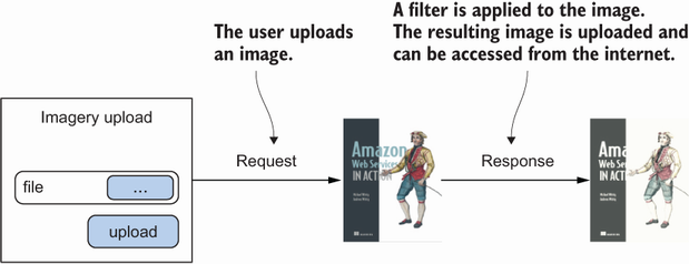
The problem with the process shown in figure 16.7 is that it’s synchronous. If the web server crashes during request and response, the user’s image won’t be processed. Another problem arises when many users want to use the Imagery app: the system becomes busy and may slow down or stop working. Therefore, the process should be turned into an asynchronous one. Chapter 14 introduced the idea of asynchronous decoupling by using an SQS message queue, as shown in figure 16.8.

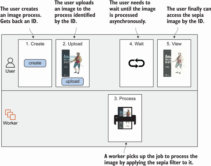
When designing an asynchronous process, it’s important to keep track of the process. You need some kind of identifier for it. When a user wants to upload an image, the user creates a process first. This returns a unique ID. With that ID, the user can upload an image. If the image upload is finished, the worker begins to process the image in the background. The user can look up the process at any time with the process ID. While the image is being processed, the user can’t see the sepia image, but as soon as the image is processed, the lookup process returns the sepia image. Figure 16.9 shows the asynchronous process.
Now that you have an asynchronous process, it’s time to map that process to AWS services. Keep in mind that many services on AWS are fault tolerant by default, so it makes sense to pick them whenever possible. Figure 16.10 shows one way of doing it.

To make things as easy as possible, all the actions will be accessible via a REST API, which will be provided by EC2 instances. In the end, EC2 instances will provide the process and make calls to all the AWS services shown in figure 16.10.
You’ll use many AWS services to implement the Imagery application. Most of them are fault tolerant by default, but EC2 isn’t. You’ll deal with that problem using an idempotent state machine, as introduced in the next section.
16.3.1 The idempotent state machine
An idempotent state machine sounds complicated. We’ll take some time to explain it because it’s the heart of the Imagery application. Let’s look at what a state and machine is and what idempotent means in this context.
A finite state machine has at least one start state and one end state. Between the start and the end states, the state machine can have many other states. The machine also defines transitions between states. For example, a state machine with three states could look like this:
But there is no transition possible between (A) → (C) or (B) → (A). With this in mind, we apply the theory to our Imagery example. The Imagery state machine could look like this:
Once a new process (state machine) is created, the only transition possible is to Uploaded. To make this transition happen, you need the S3 key of the uploaded raw image. The transition between Created → Uploaded can be defined by the function uploaded(s3Key). Basically, the same is true for the transition Uploaded → Processed. This transition can be done with the S3 key of the sepia image: processed(s3Key).
Don’t be confused by the fact that the upload and the image filter processing don’t appear in the state machine. These are the basic actions that happen, but we’re interested only in the results; we don’t track the progress of the actions. The process isn’t aware that 10% of the data has been uploaded or 30% of the image processing is done. It cares only whether the actions are 100% done. You can probably imagine a bunch of other states that could be implemented, but we’re skipping that for the purpose of simplicity in this example: resized and shared are just two examples.
An idempotent state transition must have the same result no matter how often the transition takes place. If you can make sure that your state transitions are idempotent, you can do a simple trick: if you experience a failure during transitioning, you retry the entire state transition.
Let’s look at the two state transitions you need to implement. The first transition Created → Uploaded can be implemented like this (pseudocode):
uploaded(s3Key) {
  process = DynamoDB.getItem(processId)
  if (process.state !== 'Created') {
    throw new Error('transition not allowed')
  }
  DynamoDB.updateItem(processId, {'state': 'Uploaded', 'rawS3Key': s3Key})
  SQS.sendMessage({'processId': processId, 'action': 'process'});
}
The problem with this implementation is that it’s not idempotent. Imagine that SQS.sendMessage fails. The state transition will fail, so you retry. But the second call to uploaded(s3Key) will throw a “transition not allowed” error because DynamoDB .updateItem was successful during the first call.
To fix that, you need to change the if statement to make the function idempotent, like this (pseudocode):
uploaded(s3Key) {
  process = DynamoDB.getItem(processId)
  if (process.state !== 'Created' && process.state !== 'Uploaded') {
    throw new Error('transition not allowed')
  }
  DynamoDB.updateItem(processId, {'state': 'Uploaded', 'rawS3Key': s3Key})
  SQS.sendMessage({'processId': processId, 'action': 'process'});
}
If you retry now, you’ll make multiple updates to Dynamo, which doesn’t hurt. And you may send multiple SQS messages, which also doesn’t hurt, because the SQS message consumer must be idempotent as well. The same applies to the transition Uploaded → Processed.
One little thing is still missing. So far, the code will fetch an item from DynamoDB and will update the item a few lines after that. In between, another process might have set the state to Uploaded already. Luckily, the database supports conditional updates, which allows us to reduce all the logic into a single DynamoDB request. DynamoDB will evaluate the condition before updating the item, as shown here (pseudocode):
uploaded(s3Key) {
  process = DynamoDB.getItem(processId)
  DynamoDB.updateItem(processId, {
    'state': 'Uploaded',
    'rawS3Key': s3Key,
    condition: 'NOT state IN(Created, Uploaded)'
  })
  SQS.sendMessage({'processId': processId, 'action': 'process'});
}
Next, you’ll begin to implement the Imagery server.
16.3.2 Implementing a fault-tolerant web service
We’ll split the Imagery application into two parts: the web servers and the workers. As illustrated in figure 16.11, the web servers provide the REST API to the user, and the workers process images.

The REST API will support the following routes:
-
POST/image—A new image process is created when executing this route. -
GET/image/:id—This route returns the state of the process specified with the path parameter:id. -
POST/image/:id/upload—This route offers a file upload for the process specified with the path parameter:id.
To implement the web server, you’ll again use Node.js and the Express web application framework. You’ll use the Express framework, but don’t feel intimidated because you won’t need to understand it in depth to follow along.
Setting up the web server project
As always, you need some boilerplate code to load dependencies, initial AWS endpoints, and things like that. The next listing explains the code to do so.
Listing 16.1 Initializing the Imagery server (server/server.js)
const express = require('express');                      ①
const bodyParser = require('body-parser');
const AWS = require('aws-sdk');
const { v4: uuidv4 }  = require('uuid');
const multiparty = require('multiparty');

const db = new AWS.DynamoDB({});                         ②
const sqs = new AWS.SQS({});                             ③
const s3 = new AWS.S3({});                               ④

const app = express();                                   ⑤
app.use(bodyParser.json());                              ⑥

// [...]

app.listen(process.env.PORT || 8080, function() {        ⑦
  console.log('Server started. Open http://localhost:'
➥ + (process.env.PORT || 8080) + ' with browser.');
});
① Loads the Node.js modules (dependencies)
⑤ Creates an Express application
⑥ Tells Express to parse the request bodies
⑦ Starts Express on the port defined by the environment variable PORT, or defaults to 8080
Don’t worry too much about the boilerplate code; the interesting parts will follow.
Creating a new Imagery process
To provide a REST API to create image processes, a fleet of EC2 instances will run Node.js code behind a load balancer. The image processes will be stored in DynamoDB. Figure 16.12 shows the flow of a request to create a new image process.

You’ll now add a route to the Express application to handle POST /image requests, as shown in the following listing.
Listing 16.2 Creating an image process with POST /image
app.post('/image', function(request, response) {        ①
   const id = uuidv4();                                 ②
   db.putItem({                                         ③
    'Item': {
      'id': {
        'S': id                                         ④
      },
      'version': {
        'N': '0'                                        ⑤
      },
      'created': {
        'N': Date.now().toString()                      ⑥
      },
      'state': {
        'S': 'created'                                  ⑦
      }
    },
    'TableName': 'imagery-image',                       ⑧
    'ConditionExpression': 'attribute_not_exists(id)'   ⑨
  }, function(err, data) {
    if (err) {
      throw err;
    } else {
      response.json({'id': id, 'state': 'created'});    ⑩
    }
  });
});
① Registers the route with Express
② Creates a unique ID for the process
③ Invokes the putItem operation on DynamoDB
④ The id attribute will be the primary key in DynamoDB.
⑤ Uses the version for optimistic locking (explained in the following sidebar)
⑥ Stores the date and time when the process was created
⑦ The process is now in the created state: this attribute will change when state transitions happen.
⑧ The DynamoDB table will be created later in the chapter.
⑨ Prevents the item from being replaced if it already exists
⑩ Responds with the process ID
A new process can now be created.
The next route you need to implement is to look up the current state of a process.
You’ll now add a route to the Express application to handle GET /image/:id requests. Figure 16.13 shows the request flow.

Express will take care of the path parameter :id by providing it within request .params.id. The implementation shown in the next listing needs to get an item from DynamoDB based on the path parameter ID.
Listing 16.3 GET /image/:id looks up an image process (server/server.js)
function mapImage = function(item) {                      ①
  return {
    'id': item.id.S,
    'version': parseInt(item.version.N, 10),
    'state': item.state.S,
    'rawS3Key': // [...]
    'processedS3Key': // [...]
    'processedImage': // [...]
  };
};

function getImage(id, cb) {
  db.getItem({                                            ②
    'Key': {
      'id': {                                             ③
        'S': id
      }
    },
    'TableName': 'imagery-image'
  }, function(err, data) {
    if (err) {
      cb(err);
    } else {
      if (data.Item) {
        cb(null, mapImage(data.Item));
      } else {
        cb(new Error('image not found'));
      }
    }
  });
}

app.get('/image/:id', function(request, response) {       ④
  getImage(request.params.id, function(err, image) {
    if (err) {
      throw err;
    } else {
      response.json(image);                               ⑤
    }
  });
});
① Helper function to map a DynamoDB result to a JavaScript object
② Invokes the getItem operation on DynamoDB
④ Registers the route with Express
⑤ Responds with the image process
The only thing missing is the upload part, which comes next.
Uploading an image via a POST request requires several steps:

The next code listing shows the implementation of these steps.
Listing 16.4 POST /image/:id/upload uploads an image (server/server.js)
function uploadImage(image, part, response) {
  const rawS3Key = 'upload/' + image.id + '-'
➥ + Date.now();                                                 ①
  s3.putObject({                                                 ②
    'Bucket': process.env.ImageBucket,                           ③
    'Key': rawS3Key,
    'Body': part,                                                ④
    'ContentLength': part.byteCount
  }, function(err, data) {
    if (err) { /* [...] */ } else {
      db.updateItem({                                            ⑤
        'Key': {'id': {'S': image.id}},
        'UpdateExpression': 'SET #s=:newState,                   ⑥
➥ version=:newVersion, rawS3Key=:rawS3Key',
        'ConditionExpression': 'attribute_exists(id)             ⑦
➥ AND version=:oldVersion
➥ AND #s IN (:stateCreated, :stateUploaded)',
        'ExpressionAttributeNames': {'#s': 'state'},
        'ExpressionAttributeValues': {
          ':newState': {'S': 'uploaded'},
          ':oldVersion': {'N': image.version.toString()},
          ':newVersion': {'N': (image.version + 1).toString()},
          ':rawS3Key': {'S': rawS3Key},
          ':stateCreated': {'S': 'created'},
          ':stateUploaded': {'S': 'uploaded'}
        },
        'ReturnValues': 'ALL_NEW',
        'TableName': 'imagery-image'
      }, function(err, data) {
        if (err) { /* [...] */ } else {
          sqs.sendMessage({                                      ⑧
            'MessageBody': JSON.stringify({                      ⑨
              'imageId': image.id, 'desiredState': 'processed'
            }),
            'QueueUrl': process.env.ImageQueue,                  ⑩
          }, function(err) {
            if (err) {
              throw err;
            } else {
              response.redirect('/#view=' + image.id);
              response.end();
            }
          });
        }
      });
    }
  });
}
app.post('/image/:id/upload', function(request,
➥ response) {                                                   ⑪
  getImage(request.params.id, function(err, image) {
    if (err) { /* [...] */ } else {
      const form = new multiparty.Form();                        ⑫
      form.on('part', function(part) {
        uploadImage(image, part, response);
      });
      form.parse(request);
    }
  });
});
① Creates a key for the S3 object
② Calls the S3 API to upload an object
③ The S3 bucket name is passed in as an environment variable (the bucket will be created later in the chapter).
④ The body is the uploaded stream of data.
⑤ Calls the DynamoDB API to update an object
⑥ Updates the state, version, and raw S3 key
⑦ Updates only when the item exists. Version equals the expected version, and state is one of those allowed.
⑧ Calls the SQS API to publish a message
⑨ Creates the message body containing the image’s ID and the desired state
⑩ The queue URL is passed in as an environment variable.
⑪ Registers the route with Express
⑫ We are using the multiparty module to handle multipart uploads.
The server side is finished. Next, you’ll continue to implement the processing part in the Imagery worker. After that, you can deploy the application.
16.3.3 Implementing a fault-tolerant worker to consume SQS messages
The Imagery worker processes images by applying a sepia filter asynchronously. The worker runs through the following steps in an endless loop. It is worth noting that multiple workers can run at the same time:
To get started, you need some boilerplate code to load dependencies, initial AWS endpoints, and an endless loop to receive messages. The following listing explains the details.
Listing 16.5 Initializing the Imagery worker (worker/worker.js)
const AWS = require('aws-sdk');                                ①
const assert = require('assert-plus');
const Jimp = require('jimp');
const fs = require('fs/promises');

const db = new AWS.DynamoDB({});                               ②
const s3 = new AWS.S3({});
const sqs = new AWS.SQS({});

const states = {
  'processed': processed
};

async function processMessages() {                             ③
  let data = await sqs.receiveMessage({                        ④
    QueueUrl: process.env.ImageQueue,
    MaxNumberOfMessages: 1
  }).promise();
  if (data.Messages && data.Messages.length > 0) {
    var task = JSON.parse(data.Messages[0].Body);
    var receiptHandle = data.Messages[0].ReceiptHandle;
    assert.string(task.imageId, 'imageId');                    ⑤
    assert.string(task.desiredState, 'desiredState');
    let image = await getImage(task.imageId);                  ⑥
    if (typeof states[task.desiredState] === 'function') {
      await states[task.desiredState](image);                  ⑦
      await sqs.deleteMessage({                                ⑧
        QueueUrl: process.env.ImageQueue,
        ReceiptHandle: receiptHandle
      }).promise();
    } else {
      throw new Error('unsupported desiredState');
    }
  }
}

async function run() {
  while (true) {                                               ⑨
    try {
    await processMessages();
    await new Promise(resolve => setTimeout(resolve,
➥ 10000));                                                    ⑩
    } catch (e) {                                              ⑪
      console.log('ERROR', e);
    }
  }
}

run();
① Loads the Node.js modules (dependencies)
② Configures the clients to interact with AWS services
③ This function reads messages from the queue, processes them, and finally deletes the message from the queue.
④ Reads one message from the queue; might return an empty result if there are no messages in the queue
⑤ Makes sure the message contains all the required properties
⑥ Gets the process data from the database
⑧ If the message was processed successfully, deletes the message from the queue
⑪ Catches all exceptions, ignores them, and tries again
The Node.js module jimp is used to create sepia images. You’ll wire that up next.
Handling SQS messages and processing the image
The SQS message to trigger the image processing is handled by the worker. Once a message is received, the worker starts to download the raw image from S3, applies the sepia filter, and uploads the processed image back to S3. After that, the process state in DynamoDB is modified. Figure 16.15 shows the steps.

The code to process an image appears next.
Listing 16.6 Imagery worker: Handling SQS messages (worker/worker.js)
async function processImage(image) {
  let processedS3Key = 'processed/' + image.id + '-' + Date.now() + '.png';
  let rawFile = './tmp_raw_' + image.id;
  let processedFile = './tmp_processed_' + image.id;
  let data = await s3.getObject({                                  ①
    'Bucket': process.env.ImageBucket,
    'Key': image.rawS3Key
  }).promise();
  await fs.writeFile(rawFile, data.Body,
➥ {'encoding': null});                                            ②
  let lenna = await Jimp.read(rawFile);                            ③
  await lenna.sepia().write(processedFile);                        ④
  await fs.unlink(rawFile);                                        ⑤
  let buf = await fs.readFile(processedFile,
➥ {'encoding': null});                                            ⑥
  await s3.putObject({                                             ⑦
    'Bucket': process.env.ImageBucket,
    'Key': processedS3Key,
    'ACL': 'public-read',
    'Body': buf,
    'ContentType': 'image/png'
  }).promise();
  await fs.unlink(processedFile);                                  ⑧
  return processedS3Key;
}

async function processed(image) {
  let processedS3Key = await processImage(image);
  await db.updateItem({                                            ⑨
    'Key': {
      'id': {
        'S': image.id
      }
    },
    'UpdateExpression':
      'SET #s=:newState, version=:newVersion,
➥ processedS3Key=:processedS3Key',                                ⑩
    'ConditionExpression':
      'attribute_exists(id) AND version=:oldVersion
➥ AND #s IN (:stateUploaded, :stateProcessed)',                   ⑪
    'ExpressionAttributeNames': {
      '#s': 'state'
    },
    'ExpressionAttributeValues': {
      ':newState': {'S': 'processed'},
      ':oldVersion': {'N': image.version.toString()},
      ':newVersion': {'N': (image.version + 1).toString()},
      ':processedS3Key': {'S': processedS3Key},
      ':stateUploaded': {'S': 'uploaded'},
      ':stateProcessed': {'S': 'processed'}
    },
    'ReturnValues': 'ALL_NEW',
    'TableName': 'imagery-image'
  }).promise();
}
① Fetches the original image from S3
② Writes the original image to a temporary folder on disk
③ Reads the file with the image manipulation library
④ Applies the sepia filter and writes the processed image to disk
⑤ Deletes the original image from the temporary folder
⑦ Uploads the processed image to S3
⑧ Deletes the processed file from the temporary folder
⑨ Updates the database item by calling the updateItem operation
⑩ Updates the state, version, and processed S3 key
⑪ Updates only when an item exists, the version equals the expected version, and the state is one of those allowed
The worker is ready to manipulate your images. The next step is to deploy all that code to AWS in a fault-tolerant way.
16.3.4 Deploying the application
As before, you’ll use CloudFormation to deploy the application. The infrastructure consists of the following building blocks:
It takes quite a while to create that CloudFormation stack; that’s why you should do so now. After you’ve created the stack, we’ll look at the template. After that, the application should be ready to use.
To help you deploy Imagery, we have created a CloudFormation template located at http://s3.amazonaws.com/awsinaction-code3/chapter16/template.yaml. Create a stack based on that template. The stack output EndpointURL returns the URL that you can access from your browser to use Imagery. Here’s how to create the stack from the terminal:
$ aws cloudformation create-stack --stack-name imagery
➥ --template-url https:/ /s3.amazonaws.com/
➥ awsinaction-code3/chapter16/template.yaml
➥ --capabilities CAPABILITY_IAM
Next, let’s have a look what is going on behind the scenes.
Bundling runtime and application into a machine image (AMI)
In chapter 15, we introduced the concept of immutable machines. The idea is to create an Amazon Machine Image (AMI) containing the runtime, all required libraries, and the application’s code or binary. The AMI is then used to launch EC2 instances with everything preinstalled. To deliver a new version of your application, you would create a new image, launch new instances, and terminate the old instances. We used Packer by HashiCorp to build AMIs. Check out chapter 15 if you want to recap the details. All we want to show here is the configuration file we used to prebuild and share AMIs containing the Imagery worker and server with you.
Listing 16.7 explains the configuration file we used to build the AMIs for you. Please note: you do not need to run Packer to build your own AMIs. We have done so already and shared the AMIs publicly.
Find the Packer configuration file at chapter16/imagery.pkr.hcl in our source code repository at https://github.com/AWSinAction/code3.
Listing 16.7 Configuring Packer to build an AMI containing the Imagery app
packer {                                                               ①
  required_plugins {
    amazon = {                                                         ②
      version = ">= 0.0.2"
      source  = "github.com/hashicorp/amazon"
    }
  }
}

source "amazon-ebs" "imagery" {                                        ③
  ami_name      = "awsinaction-imagery-{{timestamp}}"                  ④
  tags = {                                                             ⑤
    Name = "awsinaction-imagery"
  }
  instance_type = "t2.micro"                                           ⑥
  region        = "us-east-1"                                          ⑦
  source_ami_filter {                                                  ⑧
    filters = {
      name                = "amzn2-ami-hvm-2.0.*-x86_64-gp2"
      root-device-type    = "ebs"
      virtualization-type = "hvm"
    }
    most_recent = true
    owners      = ["137112412989"]
  }
  ssh_username = "ec2-user"                                            ⑨
  ami_groups = ["all"]                                                 ⑩
  ami_regions = [                                                      ⑪
    "us-east-1",
    # [...]
  ]
}

build {                                                                ⑫
  name    = "awsinaction-imagery"                                      ⑬
  sources = [
    "source.amazon-ebs.imagery"                                        ⑭
  ]

  provisioner "file" {
    source = "./"                                                      ⑮
    destination = "/home/ec2-user/"                                    ⑯
  }

  provisioner "shell" {                                                ⑰
    inline = [
      "curl -sL https:/ /rpm.nodesource.com/setup_14.x | sudo bash -", ⑱
      "sudo yum update",
      "sudo yum install -y nodejs cairo-devel
➥ libjpeg-turbo-devel",                                               ⑲
      "cd server/ && npm install && cd -",                             ⑳
      "cd worker/ && npm install && cd -"
    ]
  }
}
① Initializes and configures Packer
② Adds the plug-in required to build AMIs
③ Configures how Packer will create the AMI
④ The name for the AMI created by Packer
⑤ The tags for the AMI created by Packer
⑥ The instance type used by Packer when spinning up a virtual machine to build the AMI
⑦ The region used by Packer to create the AMI
⑧ The filter describes how to find the base AMI—the latest version of Amazon Linux 2—from which to start.
⑨ The username required to connect to the build instance via SSH
⑩ Allows anyone to access the AMI
⑪ Copies the AMI to all commercial regions
⑫ Configures the steps Packer executes while building the image
⑭ The sources for the build (references source from above)
⑮ Copies all files and folders from the current directory ...
⑯ ... to the home directory of the EC2 instance used to build the AMI
⑰ Executes a shell script on the EC2 instance used to build the AMI
⑱ Adds a repository for Node.js 14, the runtime for the Imagery server and worker
⑲ Installs Node.js and the libraries needed to manipulate images
⑳ Installs Node.js packages for the server and worker
Next, you will learn how to deploy the infrastructure with the help of CloudFormation.
Deploying S3, DynamoDB, and SQS
The next code listing describes the VPC, S3 bucket, DynamoDB table, and SQS queue.
Listing 16.8 Imagery CloudFormation template: S3, DynamoDB, and SQS
---
AWSTemplateFormatVersion: '2010-09-09'
Description: 'AWS in Action: chapter 16'
Mappings:
  RegionMap:                                          ①
    'us-east-1':
      AMI: 'ami-0ad3c79dfb359f1ba'
    # [...]
Resources:
  VPC:                                                ②
    Type: 'AWS::EC2::VPC'
    Properties:
      CidrBlock: '172.31.0.0/16'
      EnableDnsHostnames: true
  # [...]
  Bucket:                                             ③
    Type: 'AWS::S3::Bucket'
    Properties:
      BucketName: !Sub 'imagery-${AWS::AccountId}'    ④
      WebsiteConfiguration:
        ErrorDocument: error.html
        IndexDocument: index.html
  Table:                                              ⑤
    Type: 'AWS::DynamoDB::Table'
    Properties:
      AttributeDefinitions:
      - AttributeName: id                             ⑥
        AttributeType: S
      KeySchema:
      - AttributeName: id
        KeyType: HASH
      ProvisionedThroughput:
        ReadCapacityUnits: 1
        WriteCapacityUnits: 1
      TableName: 'imagery-image'
  SQSDLQueue:                                         ⑦
    Type: 'AWS::SQS::Queue'
    Properties:
      QueueName: 'imagery-dlq'
  SQSQueue:                                           ⑧
    Type: 'AWS::SQS::Queue'
    Properties:
      QueueName: imagery
      RedrivePolicy:
        deadLetterTargetArn: !Sub '${SQSDLQueue.Arn}'
        maxReceiveCount: 10                           ⑨
# [...]
Outputs:
  EndpointURL:                                        ⑩
    Value: !Sub 'http://${LoadBalancer.DNSName}'
    Description: Load Balancer URL
① The map contains key-value pairs mapping regions to AMIs built by us including the Imagery server and worker.
② The CloudFormation template contains a typical public VPC configuration.
③ A S3 bucket for uploaded and processed images, with web hosting enabled
④ The bucket name contains the account ID to make the name unique.
⑤ DynamoDB table containing the image processes
⑥ The id attribute is used as the partition key.
⑦ The SQS queue that receives messages that can’t be processed
⑧ The SQS queue to trigger image processing
⑨ If a message is received more than 10 times, it’s moved to the dead-letter queue.
⑩ Visit the output with your browser to use Imagery.
The concept of a dead-letter queue (DLQ) needs a short introduction here as well. If a single SQS message can’t be processed, the message becomes visible again on the queue after reaching its visibility timeout for other workers. This is called a retry. But if for some reason every retry fails (maybe you have a bug in your code), the message will reside in the queue forever and may waste a lot of resources because of all the retries. To avoid this, you can configure a dead-letter queue. If a message is retried more than a specific number of times, it’s removed from the original queue and forwarded to the DLQ. The difference is that no worker listens for messages on the DLQ. You should create a CloudWatch alarm that triggers if the DLQ contains more than zero messages, because you need to investigate this problem manually by looking at the message in the DLQ. Once the bug is fixed, you can move the messages from the dead letter queue back to the original queue to process them again.
Now that the basic resources have been designed, let’s move on to the more specific resources.
IAM roles for server and worker EC2 instances
Remember that it’s important to grant only the privileges that are necessary. All server instances must be able to do the following:
-
sqs:SendMessageto the SQS queue created in the template to trigger image processing -
s3:PutObjectto the S3 bucket created in the template to upload a file to S3 (You can further limit writes to theupload/key prefix.) -
dynamodb:GetItem,dynamodb:PutItem, anddynamodb:UpdateItemto the DynamoDB table created in the template
All worker instances must be able to do the following:
-
sqs:DeleteMessage, andsqs:ReceiveMessageto the SQS queue created in the template -
s3:PutObjectto the S3 bucket created in the template to upload a file to S3 (You can further limit writes to theprocessed/key prefix.) -
dynamodb:GetItemanddynamodb:UpdateItemto the DynamoDB table created in the template
Both servers and workers need to grant access for the AWS Systems Manager to enable access via Session Manager as follows:
If you don’t feel comfortable with IAM roles, take a look at the book’s code repository on GitHub at https://github.com/AWSinAction/code3. The template with IAM roles can be found in /chapter16/template.yaml.
Now it’s time to deploy the server.
Deploying the server with a load balancer and an Auto Scaling group
The Imagery server allows the user to upload images, monitor the processing, and show the results. An Application Load Balancer (ALB) acts as the entry point into the system. Behind the load balancer, a fleet of servers running on EC2 instances answers incoming HTTP requests. An Auto Scaling group ensures EC2 instances are up and running and replaces instances that fail the load balancer’s health check.
The following listing shows how to create the load balancer with the help of CloudFormation.
Listing 16.9 CloudFormation template: Load balancer for the Imagery server
LoadBalancer:                                      ①
  Type: 'AWS::ElasticLoadBalancingV2::LoadBalancer'
  Properties:
    Subnets:
    - Ref: SubnetA
    - Ref: SubnetB
    SecurityGroups:
    - !Ref LoadBalancerSecurityGroup
    Scheme: 'internet-facing'
  DependsOn: VPCGatewayAttachment
LoadBalancerListener:                               ②
  Type: 'AWS::ElasticLoadBalancingV2::Listener'
  Properties:
    DefaultActions:
    - Type: forward                                 ③
      TargetGroupArn: !Ref LoadBalancerTargetGroup
    LoadBalancerArn: !Ref LoadBalancer
    Port: 80                                        ④
    Protocol: HTTP
LoadBalancerTargetGroup:                            ⑤
  Type: 'AWS::ElasticLoadBalancingV2::TargetGroup'
  Properties:
    HealthCheckIntervalSeconds: 5                   ⑥
    HealthCheckPath: '/'
    HealthCheckPort: 8080
    HealthCheckProtocol: HTTP
    HealthCheckTimeoutSeconds: 3
    HealthyThresholdCount: 2
    UnhealthyThresholdCount: 2
    Matcher:
      HttpCode: '200,302'
    Port: 8080                                      ⑦
    Protocol: HTTP
    VpcId: !Ref VPC
LoadBalancerSecurityGroup:                          ⑧
  Type: 'AWS::EC2::SecurityGroup'
  Properties:
    GroupDescription: 'awsinaction-elb-sg'
    VpcId: !Ref VPC
    SecurityGroupIngress:
    - CidrIp: '0.0.0.0/0'                           ⑨
      FromPort: 80
      IpProtocol: tcp
      ToPort: 80
① The load balancer distributes incoming requests among a fleet of virtual machines.
② Configures a listener for the load balancer
③ The HTTP listener forwards all requests to the default target group defined below.
④ The listener will listen for HTTP requests on port 80/TCP.
⑥ The target group will check the health of registered EC2 instances by sending HTTP requests on port 8080/TCP.
⑦ By default, the target group will forward requests to port 8080/TCP of registered virtual machines.
⑧ A security group for the load balancer
⑨ Allows incoming traffic on port 80/TCP from anywhere
Next, creating an Auto Scaling group to launch EC2 instances and registering them at the load balancer is illustrated in the following listing.
Listing 16.10 CloudFormation template: Auto Scaling group for the Imagery server
ServerSecurityGroup:                                         ①
  Type: 'AWS::EC2::SecurityGroup'
  Properties:
    GroupDescription: 'imagery-worker'
    VpcId: !Ref VPC
    SecurityGroupIngress:
    - FromPort: 8080                                         ②
      IpProtocol: tcp
      SourceSecurityGroupId: !Ref LoadBalancerSecurityGroup
      ToPort: 8080
ServerLaunchTemplate:                                        ③
  Type: 'AWS::EC2::LaunchTemplate'
  Properties:
    LaunchTemplateData:
      IamInstanceProfile:
        Name: !Ref ServerInstanceProfile
      ImageId: !FindInMap [RegionMap, !Ref
➥ 'AWS::Region', AMI]                                       ④
      Monitoring:
        Enabled: false
      InstanceType: 't2.micro'                               ⑤
      NetworkInterfaces:                                     ⑥
      - AssociatePublicIpAddress: true
        DeviceIndex: 0
        Groups:
        - !Ref ServerSecurityGroup
      UserData:                                              ⑦
        'Fn::Base64': !Sub |
          #!/bin/bash -ex
          trap '/opt/aws/bin/cfn-signal -e 1
➥ --region ${AWS::Region} --stack ${AWS::StackName}
➥ --resource ServerAutoScalingGroup' ERR
          cd /home/ec2-user/server/
          sudo -u ec2-user ImageQueue=${SQSQueue} ImageBucket=${Bucket}
➥ nohup node server.js > server.log &
          /opt/aws/bin/cfn-signal -e $? --stack ${AWS::StackName}
➥ --resource ServerAutoScalingGroup --region ${AWS::Region}
ServerAutoScalingGroup:                                      ⑧
  Type: 'AWS::AutoScaling::AutoScalingGroup'
  Properties:
    LaunchTemplate:                                          ⑨
      LaunchTemplateId: !Ref ServerLaunchTemplate
      Version: !GetAtt 'ServerLaunchTemplate.LatestVersionNumber'
    MinSize: 1                                               ⑩
    MaxSize: 2
    DesiredCapacity: 1
    TargetGroupARNs:                                         ⑪
    - !Ref LoadBalancerTargetGroup
    HealthCheckGracePeriod: 120
    HealthCheckType: ELB                                     ⑫
    VPCZoneIdentifier:                                       ⑬
    - !Ref SubnetA
    - !Ref SubnetB
    # [...]
  DependsOn: VPCGatewayAttachment
  # [...]
① A security group for the EC2 instances running the server
② Allows incoming traffic on port 8080/TCP but only from the load balancer
③ The launch template used as a blueprint for spinning up EC2 instances
④ Looks up the AMI with the Imagery server preinstalled from the region map (see listing 16.9)
⑤ Launches virtual machines of type t2.micro to run examples under the Free Tier
⑥ Configures a network interface (ENI) with a public IP address and the security group of the server
⑦ Each virtual machine will execute this script at the end of the boot process. The script starts the Node.js server.
⑧ Creates an Auto Scaling group that manages the virtual machines running the Imagery server
⑨ References the launch template
⑩ The Auto Scaling group will spin up at least one and no more than two EC2 instances.
⑪ The Auto Scaling group will register and deregister virtual machines at the target group.
⑫ The Auto Scaling group will replace EC2 instances that fail the target group’s health check.
⑬ Spins up EC2 instances distributed among two subnets and, therefore, two AZs
That’s it for the server. Next, you need to deploy the worker.
Deploying the worker with an Auto Scaling group
Deploying the worker works similar to the process for the server. Instead of a load balancer, however, the queue is used for decoupling. Please note that we already explained how to create a SQS in listing 16.8. Therefore, all that’s left is the Auto Scaling group and a launch template. The next listing shows the details.
Listing 16.11 Load balancer and Auto Scaling group for the Imagery worker
WorkerLaunchTemplate:                                 ①
  Type: 'AWS::EC2::LaunchTemplate'
  Properties:
    LaunchTemplateData:
      IamInstanceProfile:                             ②
        Name: !Ref WorkerInstanceProfile
      ImageId: !FindInMap [RegionMap, !Ref
➥ 'AWS::Region', AMI]                                ③
      Monitoring:                                     ④
        Enabled: false
      InstanceType: 't2.micro'                        ⑤
      NetworkInterfaces:                              ⑥
      - AssociatePublicIpAddress: true
        DeviceIndex: 0
        Groups:
        - !Ref WorkerSecurityGroup
      UserData:                                       ⑦
        'Fn::Base64': !Sub |
          #!/bin/bash -ex
          trap '/opt/aws/bin/cfn-signal -e 1 --region ${AWS::Region}
➥ --stack ${AWS::StackName} --resource WorkerAutoScalingGroup' ERR
          cd /home/ec2-user/worker/
          sudo -u ec2-user ImageQueue=${SQSQueue} ImageBucket=${Bucket}
➥ nohup node worker.js > worker.log &
          /opt/aws/bin/cfn-signal -e $? --stack ${AWS::StackName}
➥ --resource WorkerAutoScalingGroup --region ${AWS::Region}
WorkerAutoScalingGroup:                               ⑧
  Type: 'AWS::AutoScaling::AutoScalingGroup'
  Properties:
    LaunchTemplate:                                   ⑨
      LaunchTemplateId: !Ref WorkerLaunchTemplate
      Version: !GetAtt 'WorkerLaunchTemplate.LatestVersionNumber'
    MinSize: 1                                        ⑩
    MaxSize: 2
    DesiredCapacity: 1
    HealthCheckGracePeriod: 120
    HealthCheckType: EC2                              ⑪
    VPCZoneIdentifier:                                ⑫
    - !Ref SubnetA
    - !Ref SubnetB
    Tags:                                             ⑬
    - PropagateAtLaunch: true
      Value: 'imagery-worker'
      Key: Name
  DependsOn: VPCGatewayAttachment
  # [...]
① The launch template used as a blueprint for spinning up EC2 instances
② Attaches an IAM role to the EC2 instances to allow the worker to access SQS, S3, and DynamoDB
③ Looks up the AMI with the Imagery worker preinstalled from the region map (see listing 16.10)
④ Disables detailed monitoring of EC2 instances to avoid costs
⑤ Launches virtual machines of type t2.micro to run examples under the Free Tier
⑥ Configures a network interface (ENI) with a public IP address and the security group of the worker
⑦ Each virtual machine will execute this script at the end of the boot process. The script starts the Node.js worker.
⑧ Creates an Auto Scaling group that manages the virtual machines running the Imagery worker
⑨ References the launch template
⑩ The Auto Scaling group will spin up at least one and no more than two EC2 instances.
⑪ The Auto Scaling group will replace failed EC2 instances.
⑫ Spins up EC2 instances distributed among two subnets: AZs
⑬ Adds a Name tag to each instance, which will show up at the Management Console, for example
After all that YAML reading, the CloudFormation stack should be created. Verify the status of your stack like this:
$ aws cloudformation describe-stacks --stack-name imagery
{
  "Stacks": [{
    [...]
    "Description": "AWS in Action: chapter 16",
    "Outputs": [{
      "Description": "Load Balancer URL",
      "OutputKey": "EndpointURL",
      "OutputValue":
➥ "http://....us-east-1.elb.amazonaws.com"    ①
    }],
    "StackName": "imagery",
    "StackStatus": "CREATE_COMPLETE"           ②
  }]
}
① Copy this output into your web browser.
② Waits until CREATE_COMPLETE is reached
The EndpointURL output of the stack contains the URL to access the Imagery application. When you open Imagery in your web browser, you can upload an image as shown in figure 16.16.

Go ahead and upload some images and enjoy watching the images being processed.
|
|
Congratulations! You have accomplished a big milestone: building a fault-tolerant application on AWS. You are only one step away from the end game, which is scaling your application dynamically based on load.
Summary
-
Fault tolerance means expecting that failures happen and designing your systems in such a way that they can deal with failure.
-
To create a fault-tolerant application, you can use idempotent actions to transfer from one state to the next.
-
State shouldn’t reside on the EC2 instance (a stateless server) as a prerequisite for fault tolerance.
-
AWS offers fault-tolerant services and gives you all the tools you need to create fault-tolerant systems. EC2 is one of the few services that isn’t fault tolerant right out of the box.
-
You can use multiple EC2 instances to eliminate the single point of failure. Redundant EC2 instances in different availability zones, started with an Auto Scaling group, are how to make EC2 fault tolerant.