
8
Supercritical CO2 and other advanced power cycles for concentrating solar thermal (CST) systems
Abstract
Subcritical steam Rankine cycles are currently used in all operating solar thermal power plants. However, thermal efficiencies of these power cycles are limited to about 42%. New types of power cycles are required to generate power at higher efficiencies in order to drive down the cost of solar thermal electricity. This chapter reviews the potential power cycles that can be employed for solar thermal power plants in the near future. Supercritical steam Rankine cycles, air and helium Brayton cycles, and supercritical carbon dioxide power cycles are described in this chapter. Special attention is given to the family of supercritical carbon dioxide power cycles. Combined power cycles are also discussed as alternatives to reduce heat rejection to the environment and further increase the thermal efficiency. Organic Rankine cycle, supercritical organic Rankine cycle, and two absorption power cycles, namely Kalina cycle and Goswami cycle, are candidates that can be used as bottoming cycles.
Keywords
Brayton cycle; Combined cycles; Power cycles; Rankine cycle; Solar thermal power plants; Supercritical carbon dioxide
8.1. Introduction
Over the past few years there has been a growing interest in generating electricity using solar thermal energy due to the potential of low-cost thermal-energy storage. Among the solar thermal power technologies, the power tower has shown the best promise because of its higher operating temperatures, which leads to better thermal-to-electric efficiency and lower overall cost. If molten salt is used as the heat transfer fluid (HTF), the temperature of the fluid leaving the receiver is about 550°C. Higher temperatures are achievable by using other types of HTFs such as air. As of 2016, traditional subcritical steam Rankine cycle (SRC) is being employed in these plants, which limits the efficiency. Therefore, it is clear that the potential of power-tower plants will not be fully utilized until new types of power cycles are put into service [11]. According to goals set in the SunShot program by the US Department of Energy (DOE), next generation of power blocks should offer a thermal efficiency close to 50% in comparison with today's SRC efficiency of 42% or less. Such high thermal efficiency needs to be achieved under dry cooling conditions because solar power plants are typically located in arid areas where water is most scarce [14]. In this chapter, supercritical SRCs, air and helium Brayton cycles, and supercritical carbon dioxide power cycles are described and discussed as the near-term potential candidates, which can fulfill such requirements.
Power conversion efficiency can be further increased by using combined power cycles [9]. In this case, a bottoming cycle utilizes the waste heat from the top cycle resulting in higher efficiency and less heat rejection to the environment. Depending on the operating temperatures, different power cycles can be employed as bottoming cycles including the subcritical SRC. In this chapter, organic Rankine cycle (ORC), supercritical organic Rankine cycle (SORC), and two absorption power cycles, namely Kalina cycle and Goswami cycle, are discussed as potential candidates.
8.2. Stand-alone cycles
In this section, stand-alone cycles that can be used for power generation in concentrating solar thermal (CST) plants are described. The section is divided into two main categories of SRCs and gas Brayton cycles.
8.2.1. Steam Rankine cycles
The SRC has been used in all existing CST plants. A schematic of a typical SRC cycle including feed water heaters and a reheater is shown in Fig. 8.1. The operating conditions are mainly dependent on the solar technology. In solar energy generating systems (SEGS) plants which use parabolic trough concentrators as the solar collectors and synthetic oil as the HTF, superheated steam is generated at 371°C and 100 bar. Using molten salt as the HTF or direct steam generation in solar power-tower plants increases the steam temperature to about 540°C, resulting in higher thermal-to-electric efficiency in the range of 42% with a wet-cooled condenser [14].
Beside increasing the temperature, elevating the steam pressure to more than its critical pressure (222 bar) leads to supercritical steam Rankine cycles (SSRCs), which give higher thermal efficiency [30]. Although SSRCs have not been utilized in the current CST plants, they have been successfully deployed in fossil fuel power plants [2].
Depending on the cycle configuration and operating temperatures, there is an optimum pressure above which the thermal efficiency does not improve much. For example, in a reheat cycle for the main/reheat temperatures of 600°C/620°C, increasing the main steam pressure above 300 bar does not offer any further economic advantage [8]. As of 2016, the high temperature of SSRCs is limited to about 627°C because of the limitation of ferritic steels. Other materials are under evaluation to operate at higher temperatures while special attention is being given to high-nickel alloys [32].
It is noteworthy that improvement in the efficiency by using supercritical steam, instead of superheated steam, comes at higher material costs. Cheang et al. [2] investigated the associated costs of the two cycles in CST plants. They concluded that using supercritical steam leads to an efficiency improvement of 4.6% while the power block capital cost is increased by 31.9%. They found the cost per kilowatt for the two plants to be about the same, which does not justify using the high-pressure working fluid. This conclusion may not hold for fossil fuel power plants, where saving fuel over the lifetime of the plant, as well as taking advantage of economy of scale (more than 400 MW), results in a lower operating cost of the SSRCs. Therefore, comprehensive lifetime cost analysis is required before deploying SSRC in the CST plants.
8.2.2. Gas Brayton cycles
Although all the operational CST plants are based on using SRCs, there is a growing interest in generating power at higher temperatures, and consequently, higher efficiencies. This requires the use of high-temperature solar receivers. Gas Brayton cycles, which have already been employed for a long time in fossil fuel power plants, are potential candidates for use in the future CST plants. Air, helium, and carbon dioxide can all be used as the working fluids.

8.2.2.1. Air Brayton cycle
Integration of the solar power-tower technology with existing gas turbines is a promising concept, which reduces the capital, and operational and maintenance costs. In this kind of technology, CST is used to preheat the pressurized air before entering the combustion chamber of the gas turbine (Fig. 8.2). Solar air preheating increases the compressed air temperature which leads to less fuel consumption. Moreover, in spite of the fluctuations in solar power input, the turbine inlet temperature remains constant and the output power is fully dispatchable. This reduces the losses due to frequent start-ups and shutdowns and part-load operation in the conventional CST plants, which results in higher system efficiency [28]. As shown in Fig. 8.2, an SRC can also be used as a bottoming cycle to further improve the thermal efficiency.
8.2.2.2. Helium Brayton cycle
Closed-loop Brayton cycles are recognized as highly efficient power cycles at relatively moderate top cycle temperatures. The high-temperature fluid leaving the turbine goes through a heat recovery unit where its thermal energy is transferred to the stream leaving the last compressor (Fig. 8.3). Using intercooling between the compressors and reheat between the turbines can further improve the efficiency. However, the efficiency benefit of reheating and intercooling decreases with every additional stage [8].

Figure 8.2 Air Brayton cycle with solar preheating. Adapted from Schwarzbözl P, Buck R, Sugarmen C, Ring A, Crespo MJM, Altwegg P, Enrile J. Solar gas turbine systems: design, cost and perspectives. Solar Energy 2006;80(10):1231–40.

A closed-loop Brayton cycle with helium as the working fluid has been considered for nuclear applications. It has been shown that a net cycle efficiency up to 48% can be achieved when the turbine inlet temperature is around 850°C to 900°C. However, for a sodium cooled fast reactor, the maximum working fluid temperature is limited to 500–550°C [39], which is achievable in the power-tower plants.
8.2.2.3. Supercritical carbon dioxide Brayton cycles
Carbon dioxide is a nontoxic, inexpensive, nonflammable, and highly stable compound with low critical properties, that is, 7.38 MPa and 30.98°C (314.13 K). Around the critical point, CO2 is not an ideal gas, and its behavior is very sensitive to pressure and temperature. In other words, the fluid properties vary significantly around the critical point. Fig. 8.4 shows the density variations of CO2 at different operating conditions. As can be seen, the density is very high around the critical point and comparable to liquid density. Therefore, the compression work is considerably reduced if carbon dioxide enters the compressor close to the critical condition, which is the main advantage of supercritical carbon dioxide (s-CO2) over the other working fluids. Wright et al. [33] compared the density of s-CO2 in a closed-loop Brayton cycle with that of water. At the specified condition, the density of the CO2 at the inlet of the compressor is 60% of the density of water, which results in low compression power requirement.

In addition to the density, other properties of CO2 also change drastically around the critical point. As can be seen from Fig. 8.5, the thermal conductivity of CO2 maximizes close to the critical point reaching 148.95  at 305 K. From Refprop [16], the thermal conductivity of water at 305 K is 618.41 , while the thermal conductivity of air is 26.355 at the atmospheric pressure and 305 K temperature.

Fig. 8.6 shows how the specific heat of CO2 changes close to the critical point. Large variations in specific heat affect the recuperator design in the power cycle. It is known that for a certain operating condition, a pinch-point exists in the recuperator. The pinch-point is the location where the temperature difference between the hot and cold streams is the lowest. As the specific heat varies radically with the changes in pressure and temperature, the temperature difference between the fluids varies widely within the recuperator. Consequently, the pinch-point location may be found somewhere inside the recuperator. Therefore, more detailed analysis of the temperature profiles is necessary to evaluate the performance of the recuperator [6]. Moreover, the recuperator size and efficiency are directly affected by the operating pressure. Therefore, unlike the recuperators for ideal gases, such as helium, where the temperature difference is almost constant and dependent only on the pressure ratio and temperatures, the operating pressure is also important and has to be optimally determined. In addition, the high specific heat of CO2 close to the critical point requires high mass flow rate of cooling water in the precooler which increases the parasitic losses [6].
There are multiple configurations of s-CO2 Brayton cycle in the literature. The three configurations that are introduced in this chapter are, simple, recompression, and partial cooling cycles.

Simple cycle
The simple cycle configuration and the corresponding temperature–entropy (T-s) diagram are shown in Fig. 8.7. Similar to the helium Brayton cycle, a heat recovery unit is used to transfer thermal energy from the high-temperature fluid leaving the turbine to the low-temperature stream. Intercooling and reheat can further increase the thermal efficiency.
Recompression cycle
In this configuration (Fig. 8.8), the fluid leaving the low-temperature recovery (LTR) unit is divided into two streams. One stream goes through the precooler, main compressor and LTR while the other stream is directly pressurized by a recompression compressor. The two streams are mixed before the high-temperature recovery (HTR). Then, thermal energy is added to achieve the required turbine inlet temperature. After expanding in the turbine, the flow is directed into HTR and LTR to preheat the high-pressure, low-temperature stream. The main advantage of this configuration over the simple cycle is more efficient heat recovery. By splitting the flow, the heat capacity of the high-pressure stream in the LTR decreases, which helps to avoid common pinch-point problems. The fraction of the flow going through the recompression compressor is an important design parameter, which directly affects the cycle thermal efficiency.
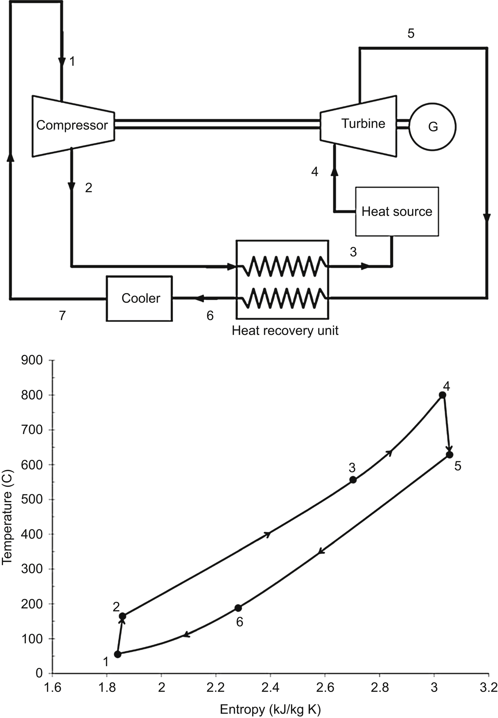
Figure 8.7 Simple s-CO2 Brayton cycle [1].

Figure 8.8 Recompression s-CO2 Brayton cycle [1].
Partial cooling cycle
This configuration (Fig. 8.9) has one more compressor and cooler in comparison with the recompression cycle. Before entering the precompressor, the low-pressure stream leaving the LTR is cooled. Then, the flow pressure is increased to an intermediate level. Next, the flow is divided into two streams. One stream enters the main compressor after rejecting heat and the other goes through the recompression compressor. The two streams are mixed before entering the HTR. Two-stage compression and the additional cooler lead to lower compression work in comparison with the previous configurations. Among these configurations the simple cycle is the least efficient. However, its simplicity and fewer numbers of components increase the potential of early commercial market entry. No definite conclusion can be reached yet, as to which of the other two configurations is more advantageous for future CST plants. Modeling the two cycles with the same effectiveness values for the heat exchangers leads to quite similar thermal efficiencies. However, more detailed analysis shows that the partial cooling cycle reaches higher efficiency than the recompression configuration when the two are compared, based on equal recuperator conductance values (UA). The difference between the thermal efficiencies can be as high as 4% for low UA values, and becomes almost zero when the UA is higher than 15 MW/K [21]. Therefore, assuming the cost of the cycle is largely dependent on the recuperator conductance, the partial cooling configuration is superior for low conductance values.

Figure 8.9 Partial cooling s-CO2 Brayton Cycle [1].
In addition, numerical analysis shows that the temperature difference between the inlet and outlet of the primary heater (states 4 and 5) is 23–35% larger in the partial cooling cycles in comparison to the recompression configuration. Higher temperature difference leads to the lower required fluid volume when sensible heat storage is employed. Therefore, the partial cooling cycle results in more cost-effective sensible heat storage. Higher temperature gradients in the receiver reduce the heat loss to the environment by lowering the average operating temperature. Moreover, partial cooling cycles operate at comparatively lower pressures, which is advantageous in terms of component designs [21].
On the other hand, a detailed analysis by [1] showed that the recompression cycle has a higher potential to be used as the top cycle in a combined s-CO2-ORC configuration. The efficiency benefit is about 2% in comparison with the combined partial cooling s-CO2-ORC cycle. Moreover, Padilla et al. [22] carried out a comprehensive exergy analysis on different s-CO2 cycle configurations, and concluded that the recompression cycle with an additional intercooler for the main compressor has the best exergetic performance.
It is noteworthy that this information is based on specific operating conditions and modeling approaches, and cannot be considered as conclusive. More studies are required in this area to further investigate the advantages and disadvantages of each cycle.
8.2.3. Comparison of the presented cycles
Dostal et al. [7] compared the thermal efficiency of a recompression s-CO2 cycle with a superheated steam Rankine, supercritical steam Rankine, and helium Brayton cycles. More detailed information about the configuration of each cycle can be found in Ref. [7]. As can be clearly seen from Fig. 8.10, s-CO2 cycle always outperforms the helium Brayton cycle for the entire temperature range. In addition, the s-CO2 cycle is more efficient than the SRC when the turbine inlet temperature is higher than 550°C. Therefore, the optimal operating temperature range for s-CO2 cycle is above 550°C. This is the temperature range that can be easily achieved in solar power towers.The expected efficiency for s-CO2 cycle in the CST plants is in the range of 43–54% under wet-cooling conditions. However, CST plants are usually located in the areas where water resources are limited; therefore, dry cooling would be preferred over wet cooling. Even under Dry-cooling conditions, close to 50% efficiency is achievable, which is consistent with the goals of the DOE SunShot program [25].

As stated earlier, the s-CO2 cycle has high efficiency due to low compression work, as the density of CO2 increases substantially around the critical point. Higher density of the working fluid also means smaller power conversion components which is another advantage [18]. Table 8.1 shows the turbine size, shaft speed, and CO2 mass flow rate for power ratings of 0.3, 3, and 300 MW. As can be seen, for 3 MW power, the turbine wheel diameter is only 15 cm with a speed of 50,000 rpm. Therefore, it is possible to place the power block inside the tower. In other words, power can be generated inside the tower right after the receiver and the fluid does not need to flow through long pipes. Hence, the system can be compact, and the pressure drop and heat loss are reduced, which consequently leads to higher efficiency and lower cost.
Table 8.1
CO2 turbine size at different power rates [18]
| Power rate (MW) | Turbine wheel diameter (m) | Desired shaft speed (rpm) | CO2 flow (kg/s) |
| 0.3 | 0.04 | 125,000 | 3.5 |
| 3 | 0.15 | 50,000 | 35 |
| 300 | 1.5 | 3,600 | 3,500 |

8.3. Combined cycles
Combined cycles can improve the overall efficiency of power conversion for CST. In this section, we introduce potential bottoming cycles that can be used in a combined cycle configuration. Any of the stand-alone cycles introduced in the previous section can serve as the topping cycle.
8.3.1. Organic Rankine cycle
The principle of operation for ORC is similar to SRC; however, an organic fluid is used instead of steam as the working fluid. Organic fluids generally have low boiling points, which makes recovering heat from low-grade heat sources possible [31]. The performance of an ORC is substantially affected by the selection of the working fluid.
Organic fluids can be categorized as dry (positive slope), wet (negative slope), and isentropic (vertical slope) fluids, depending on the slope of their saturation curves in T-s diagrams (Fig. 8.11).
The wet fluids such as water need to be superheated, while dry and isentropic fluids do not need superheating. The isentropic and dry fluids are for ORCs to protect the turbine blades from liquid droplets during expansion. However, if the fluid is “too dry,” the vapor will leave the turbine with substantial “superheat,” which adds to the cooling load of the condenser. This energy can be used to preheat the liquid before entering the evaporator to increase the cycle efficiency [4].
There is no best fluid for heat sources with different temperatures and one needs to consider multiple criteria and concerns before selecting a working fluid. These criteria are extensively discussed in [4,27,29] and can be summarized as:
1. Types of the working fluids: Dry, wet, or isentropic.

Figure 8.11 Types of organic fluids [4].
3. Critical properties: Critical properties of a fluid determine the operating conditions of temperatures and pressures in the cycle. Fluids with low critical temperatures (e.g., below 300 K) have difficulties in condensation and are usually not considered.
4. Stability of the fluid, compatibility with materials in contact, ozone depletion potential (ODP), global warming potential (GWP), the atmospheric lifetime (ALT), availability, and cost: All these are of great importance.
5. Thermal efficiency: Thermal efficiency of the cycle using the selected working fluid.
6. Turbine outlet/inlet volume flow ratio: Lower ratio allows the use of simpler and cheaper turbines.
Chen et al. [4] tabulated the thermodynamic and physical properties of 35 organic fluids which comply with environmental and safety regulations. Using the listed properties, one needs to select the potential working fluids for the heat source and sink temperatures. Then, analyzing the thermodynamic cycles with the selected working fluids can determine the best candidate for the specified conditions.
Besarati and Goswami [1] studied integration of an ORC bottoming cycle with each of the s-CO2 cycle configurations introduced in the previous sections. The best organic fluids for each configuration were shortlisted based on thermal efficiency and expansion ratio of the ORC turbine. The largest efficiency increase, close to 7%, was achieved by using a simple s-CO2 as the top cycle. However, as discussed previously, this cycle is less efficient than the recompression and partial cooling cycles. The maximum combined cycle efficiency (i.e., 54%) was obtained by the recompression s-CO2-ORC cycle using R245fa as the working fluid. The efficiency of the stand-alone cycle under the same operating conditions was around 49%.
8.3.2. Supercritical organic Rankine cycle
The principles of operation are similar to ORC, however, the working fluid with low critical properties is directly compressed to its supercritical state, bypassing the two-phase region [17]. Fig. 8.12 compares the thermal match between the heat source and two different working fluids, one in ORC and another in SORC, for the same maximum temperature and pinch-point limitation [27]. As can be seen clearly, the mean temperature difference between the heat source and the working fluid is less in the SORC, resulting in less entropy generation (lower irreversibility). On the other hand, SORCs normally operate at higher pressures than ORCs, which may lead to higher equipment costs and safety concerns.
Carbon dioxide has been frequently studied as the working fluid in SORCs [35,37,38]. The main challenge for using CO2 is its low critical temperature (i.e., about 31°C), which makes the condensation process difficult. Isobutene, propane, propylene, difluoromethane, and R-245fa are some of the other working fluids that have been studied for SORCs [4].
Another approach to reduce irreversibility and improve the system efficiency is using zeotropic mixtures of working fluids [3]. The main advantage is that the condensation process is not isothermal, and there is a better thermal match between the working fluid and the coolant. Fig. 8.13 depicts the condensation process of a zeotropic mixture of R134a and R32. As can be clearly seen, there is a thermal glide when the mixture is condensed at constant pressure. Therefore, the condensation process can be designed in a way that the temperature profile of the cooling water parallels that of SORC working fluid, resulting in less irreversibility.

Figure 8.12 (Left) T–ΔH diagram in an ORC with R152a as the working fluid at 20 bar from 31.16°C to 100°C. (Right) T–ΔH diagram in an SORC with R143a as the working fluid at 40 bar from 33.93°C to 100°C [27].

Figure 8.13 Condensation process of a zeotropic mixture of R134a and R32 and its thermal match with the coolant [3].
8.3.3. Absorption power cycles
In these type of power cycles, an ammonia–water mixture is generally used as the working fluid, where the concentration of ammonia varies at different points of the cycle. As ammonia is a more volatile component than water, it tends to vaporize at a lower temperature than pure water. Therefore, during the heating process, concentration of ammonia in the liquid working fluid decreases, resulting in a better thermal match with the heat source and lower irreversibility. Kalina and Goswami cycles are two absorption power cycles that can be used as the bottoming cycle in CST plants.
8.3.3.1. Kalina cycle
Kalina proposed a novel cycle in 1984 to be used as a bottoming cycle utilizing waste heat from the exhaust of gas turbines [13]. The proposed configuration was called Kalina cycle system 1 (KCS 1). This cycle uses ammonia–water mixture as the working fluid where the concentration of ammonia varies along the cycle. Since then, the cycle configuration has been modified for different applications and each is identified by a unique system number. For example, KCS 2 is intended for low-temperature geothermal applications and KCS 5 is applicable to direct fuel–fired plants. Different Kalina cycles along with their applications are well documented by Ref. [36]. The layout of a Kalina cycle is shown in Fig. 8.14.

In comparison with the Rankine cycle, the Kalina cycle is more complex and requires more components. On the other hand, the variable concentration of ammonia in the binary mixture provides the possibility to alter the properties of the working fluid at different locations in the cycle in order to maximize the thermal performance.
El-Sayed and Tribus [10] compared the thermal performance of steam Rankine and Kalina cycles when both are used as bottoming cycle with the same thermal boundary conditions. The results show that using the Kalina cycle leads to 10–20% improvement in the thermal efficiency. Other research papers have also indicated the advantages of Kalina over Rankine cycle (in a combined cycle configuration) from both first and second laws points of views [12,19].
Neises and Turchi [20] analyzed the performance of a combined steam Rankine–Kalina cycle in a parabolic trough solar thermal plant. It was concluded that such combined power cycle can overcome some of the drawbacks of the stand-alone SRC. These drawbacks can be summarized as:
1. Limitations in generating power during the low solar insolation periods when the steam temperature and flow rate are not satisfactory.
2. Large condensing unit due to very high specific volume of steam at the turbine outlet.
3. Vacuum pressure at the condenser.
4. Lower performance of the condensing turbines when they are used at small scales.
In their proposed cycle, condensing steam turbines are replaced by back-pressure turbines. The cycles operate in two different modes during high and low insolation modes. The Rankine cycle is bypassed during the low insolation periods (typically 300–400 W/m2). Under these conditions, the temperature of the HTF can still exceed 300°C, which is high enough for operating the Kalina cycle. When the insolation level is high, the Kalina cycle operates as the bottoming cycle utilizing the waste heat from the SRC. Operating the power block in two different modes improves the plant availability. Moreover, the condensing pressure of the combined cycle is above atmospheric, which is due to the high concentration of ammonia in the condensing unit. Moreover, back-pressure turbines operate efficiently at 5–20 MW size, which makes implementation of the technology possible for small- and medium-size power plants. A techno-economic analysis for a 50 MW parabolic trough power plant indicated that a 4–11% electricity cost saving could be achieved by replacing a stand-alone Rankine cycle with the combined Rankine–Kalina cycle.
In another study Peng et al. [24] investigated using Kalina cycle to utilize waste heat from a gas turbine. A solar power tower was used to preheat the air. A simulation showed that using Kalina instead of SRC as the bottoming cycle reduces the exergy destruction and leads to a peak solar-to-electric efficiency of 27.5% for the turbine inlet temperature of 1000°C.
8.3.3.2. Goswami cycle
Goswami proposed a thermodynamic cycle in 1995 which can be used either as a stand-alone cycle for low-temperature heat sources or a bottoming cycle [11,34]. An ammonia–water mixture is used as the working fluid and the cycle can produce both power and refrigeration, although other fluid pairs could also be used.

Fig. 8.15 shows a schematic of the cycle. The binary working fluid leaves the absorber with a relatively high ammonia concentration. It is then pressurized and receives heat from the returning weak ammonia liquid solution in the recovery heat exchanger. Next, the basic solution is partially boiled to produce a two-phase mixture. The vapor with high ammonia concentration is separated from the liquid and enters the rectifier. The rectifier cools the saturated ammonia vapor to condense out any remaining water. The liquid mixture with low ammonia concentration goes through the heat recovery unit and is throttled to the cycle's low pressure. Additional heat can be transferred to the ammonia vapor in the superheater before expanding in the turbine.
The temperature of the vapor leaving the turbine is significantly below the ambient temperature, which provides cooling in the refrigeration heat exchanger.
Similar to the Kalina cycle, the irreversibilities associated with heat transfer from a sensible heat source are reduced by boiling the ammonia–water mixture. Almost pure ammonia is expanded in the turbine. It is noteworthy that the cycle operating conditions can be optimized depending on the demand profile to generate maximum power, maximum cooling, or a combination of the two [5].
Padilla et al. [23] analyzed a 50-MW parabolic trough solar power plant with Goswami cycle serving as the condenser of a SRC. His analysis indicated that replacing the traditional condenser with the Goswami cycle reduces energy losses, and eliminates the high specific volume and poor vapor quality presented in the last stages of the turbine.
8.4. Summary and conclusions
In this chapter, power cycles that can be utilized in future CST power plants are reviewed. The Supercritical steam cycle is a highly promising candidate as the SRC is already in service at all CST plants. However, more development is required in terms of materials to enable the operation of the cycle at higher temperatures. Moreover, life cycle analysis is necessary to make sure the additional cost of using supercritical cycle does not outweigh the efficiency benefit. The air Brayton cycle is a promising candidate when a CST plant is added to an operational gas turbine to reduce fuel consumption. Direct and indirect receivers are under development with HTF exit temperatures of around 1000°C. Although helium Brayton cycle is being considered in nuclear power plants, its lower efficiency in comparison with s-CO2 Brayton cycles is a major obstacle for future development. Supercritical CO2 power cycles are superior to other stand-alone cycles at turbine inlet temperatures greater than 550°C. Both partial cooling and recompression configurations are promising and more detailed comparison is required before deploying in a power plant. Despite all the positive aspects mentioned for these types of power cycles, there are some uncertainties about utilization of s-CO2 in CST plants. The main concerns are the high pressure of the fluid and lack of experience in operating closed-loop Brayton cycles.
This chapter also describes some lower-temperature power cycles that can be used as potential bottoming cycles. Using a bottoming cycle can further improve the power cycle efficiency by minimizing the rejected heat to the environment. ORC and Kalina cycles are more developed alternatives, which have already been used to generate power from low-temperature heat sources at medium scales. The SORC and Goswami cycle can also be considered as options due to their simplicity and smooth heat addition. The efficiencies shown for each cycle in this study are dependent on the operating conditions and may differ depending on the system requirements.
Although developing new types of power cycles has been an active area of research for a number of years, additional effort is required to model the performance of power cycles, in particular at off-design conditions, which are frequently expected at the solar power plants. In addition, new types of low-cost turbo-machines need to be developed to operate at high efficiencies over a broad range of part-load conditions. The turbo-machines must respond quickly to frequent startup/shutdown operations. Moreover, employing high-temperature power cycles demands high-temperature solar receivers. Although new thermal receiver concepts such as, particle and micro-channel receivers are under development, extensive research is required before utilizing them in a solar power plant. In addition, increasing the maximum temperature of the power cycle has to be accompanied by a cost-effective thermal-storage approach. Thermochemical storage can be considered as a viable option for high temperature systems. Furthermore, low-cost recuperators need to be developed to address a challenge with s-CO2 cycles, which is the required substantial heat transfer area. Moreover, testing different types of materials such as nickel alloys is needed to find their expected thermo-mechanical properties under severe pressure and temperature conditions.
..................Content has been hidden....................
You can't read the all page of ebook, please click here login for view all page.