
Scheduling
Abstract
NR is essentially a scheduled system where the scheduler in the gNB controls downlink and uplink transmissions. This chapter describes the details around dynamic as well as semipersistent scheduling, including associated functionality such as buffer-status report and power-headroom reports.
Keywords
Scheduling; dynamic scheduling; semipersistent scheduling; preemption; buffer-status report; power-headroom report; scheduling request; discontinuous reception; DRX
NR is essentially a scheduled system, implying that the scheduler determines when and to which devices the time, frequency, and spatial resources should be assigned and what transmission parameters, including data rate, to use. Scheduling can be either dynamic or semistatic. Dynamic scheduling is the basic mode-of-operation where the scheduler for each time interval, for example, a slot, determines which devices are to transmit and receive. Since scheduling decisions are taken frequently, it is possible to follow rapid variations in the traffic demand and radio-channel quality, thereby efficiently exploiting the available resources. Semi-static scheduling implies that the transmission parameters are provided to the devices in advance and not on a dynamic basis.
In the following, dynamic downlink and uplink scheduling will be discussed, including bandwidth adaptation, followed by a discussion on non-dynamic scheduling and finally a discussion on discontinuous reception as a way to reduce device power consumption.
14.1 Dynamic Downlink Scheduling
Fluctuations in the received signal quality due to small-scale as well as large-scale variations in the environment are an inherent part in any wireless communication system. Historically, such variations were seen as a problem, but the development of channel-dependent scheduling, where transmissions to an individual device take place when the radio-channel conditions are favorable, allows these variations to be exploited. Given a sufficient number of devices in the cell having data to transfer, there is a high likelihood of at least some devices having favorable channel conditions at each point in time and able to use a correspondingly high data rate. The gain obtained by transmitting to users with favorable radio-link conditions is commonly known as multiuser diversity. The larger the channel variations and the larger the number of users in a cell, the larger the multiuser diversity gain. Channel-dependent scheduling was introduced in the later versions of the 3G standard known as HSPA [21] and is also used in LTE as well as NR.
There is a rich literature in the field of scheduling and how to exploit variations in the time and frequency domains (see, for example, Ref. [28] and the references therein). Lately, there has also been a large interest in various massive multiuser MIMO schemes [55] where a large number of antenna elements are used to create very narrow “beams,” or, expressed differently, isolate the different users in the spatial domain. It can be shown that, under certain conditions, the use of a large number of antennas results in an effect known as “channel hardening.” In essence, the rapid fluctuations of the radio-channel quality disappear, simplifying the time–frequency part of the scheduling problem at the cost of a more complicated handling of the spatial domain.
In NR, the downlink scheduler is responsible for dynamically controlling the device(s) to transmit to. Each of the scheduled devices is provided with a scheduling assignment including information on the set of time–frequency resources upon which the device’s DL-SCH1 is transmitted, the modulation-and-coding scheme, hybrid-ARQ-related information, and multi-antenna parameters as outlined in Chapter 10. In most cases the scheduling assignment is transmitted just before the data on the PDSCH, but the timing information in the scheduling assignment can also schedule in OFDM symbols later in the slot or in later slots. One use for this is bandwidth adaptation as discussed below. Changing the bandwidth part may take some time and hence data transmission may not occur in the same slot as the control signaling was received in.
It is important to understand that NR does not standardize the scheduling behavior. Only a set of supporting mechanisms are standardized on top of which a vendor-specific scheduling strategy is implemented. The information needed by the scheduler depends on the specific scheduling strategy implemented, but most schedulers need information about at least:
Additionally, the interference situation in neighboring cells can be useful if some form of interference coordination is implemented.
Information about the channel conditions at the device can be obtained in several ways. In principle, the gNB can use any information available, but typically the CSI reports from the device are used as discussed in Section 8.1. There is a wide range of CSI reports that can be configured where the device reports the channel quality in the time, frequency, and spatial domains. The amount of correlation between the spatial channels to different devices is also of interest to estimate the degree of spatial isolation between two devices in the case they are candidates for being scheduled on the same time–frequency resources using multiuser MIMO. Uplink sounding using SRS transmission can, together with assumptions on channel reciprocity, also be used to assess the downlink channel quality. Various other quantities can be used as well, for example, signal-strength measurements for different beam candidates.
The buffer status and traffic priorities are easily obtained in the downlink case as the scheduler and the transmission buffers reside in the same node. Prioritization of different traffic flows is purely implementation-specific, but retransmissions are typically prioritized over transmission of new data, at least for data flows of the same priority. Given that NR is designed to handle a much wider range of traffic types and applications than previous technologies, such as LTE, priority handling in the scheduler can in many cases be even more emphasized than in the past. In addition to selecting data from different data flows, the scheduler also has the possibility to select the transmission duration. For example, for a latency-critical service with its data mapped to a certain logical channel, it may be advantageous to select a transmission duration corresponding to a fraction of a slot, while for another service on another logical channel, a more traditional approach of using the full slot duration for transmission might be a better choice. It may also be the case that, for latency reasons and shortage of resources, an urgent transmission using a small number of transmissions needs to preempt an already ongoing transmission using the full slot. In this case, the preempted transmission is likely to be corrupted and require a retransmission, but this may be acceptable given the very high priority of the low-latency transmission. There are also some mechanisms in NR which can be used to mitigate this, as discussed in Section 14.1.2.
Different downlink schedulers may coordinate their decisions to increase the overall performance, for example, by avoiding transmission on a certain frequency range in one cell to reduce the interference towards another cell. In the case of (dynamic) TDD, the different cells can also coordinate the transmission direction, uplink or downlink, between the cells to avoid detrimental interference situations. Such coordination can take place on different time scales. Typically, the coordination is done at a slower rate than the scheduling decisions in each cell as the requirements on the backhaul connecting different gNBs otherwise would be too high.
In the case of carrier aggregation, the scheduling decisions are taken per carrier and the scheduling assignments are transmitted separately for each carrier, that is, a device scheduled to receive data from multiple carriers simultaneously receives multiple PDCCHs. A PDCCH received can either point to the same carrier, known as self-scheduling, or to another carrier, commonly referred to as cross-carrier scheduling (see Fig. 14.1). In the case of cross-carrier scheduling of a carrier with a different numerology than the one upon which the PDCCH was transmitted, timing offsets in the scheduling assignment, for example, which slot the assignment relates to, are interpreted in the PDSCH numerology (and not the PDCCH numerology).

The scheduling decisions for the different carriers are not taken in isolation. Rather, the scheduling of the different carriers for a given device needs to be coordinated. For example, if a certain piece of data is scheduled for transmission on one carrier, the same piece of data should normally not be scheduled on another carrier as well. However, it is in principle possible to schedule the same data on multiple carriers. This can be used to increase reliability; with multiple carriers transmitting the same data the likelihood of successful reception on at least one carrier is increased. At the receiver the RLC (or PDCP) layer can be configured to remove duplicates in case the same data are successfully received on multiple carriers. This results in selection diversity.
14.1.1 Bandwidth Adaptation
NR support a very wide transmission bandwidth, up to several 100 MHz on a single carrier. This is useful for rapid delivery of large payloads but is not needed for smaller payload sizes or for monitoring the downlink control channels when not scheduled. Hence, as mentioned already in Chapter 5 NR supports receiver-bandwidth adaptation such that the device can use a narrow bandwidth for monitoring control channels and only open the full bandwidth when a large amount of data is scheduled. This can be seen as discontinuous reception in the frequency domain.
Opening the wideband receiver can be done by using the bandwidth part indicator field in the DCI. If the bandwidth part indicator points to a different bandwidth part than the currently active one, the active bandwidth part is changed (see Fig. 14.2). The time it takes to change the active bandwidth part depends on several factors, for example, if the center frequency changes and the receiver needs to retune or not, but can be in the order of a slot. Once activated, the device uses the new, and wider, bandwidth part for its operation.

Upon completion of the data transfer requiring the wider bandwidth, the same mechanism can be used to revert back to the original bandwidth part. There is also a possibility to configure a timer to handle the bandwidth-part switching instead of explicit signaling. In this case, one of the bandwidth parts is configured as the default bandwidth part. If no default bandwidth part is explicitly configured, the initial bandwidth part obtained from the random-access procedure is used as the default bandwidth part. Upon receiving a DCI indicating a bandwidth part other than the default one, the timer is started. When the timer expires, the device switches back to the default bandwidth part. Typically, the default bandwidth part is narrower and can hence help reducing the device power consumption.
The introduction of bandwidth adaptation in NR raised several design questions not present in LTE, in particular related to the handling of controls signaling as many transmission parameters are configured per bandwidth part and the DCI payload size therefore may differ between different bandwidth parts. The frequency-domain resource allocation field is an obvious example; the larger the bandwidth part, the larger the number of bits for frequency-domain resource allocation. This is not an issue as long as the downlink data transmission uses the same bandwidth part as the DCI control signaling.2 However, in the case of bandwidth adaptation this is not true as the bandwidth part indicator in the DCI received in one bandwidth part can point to another differently sized bandwidth part for data reception. This raises the issue on how to interpret the DCI if the bandwidth part index points to another bandwidth part than the current one, as the DCI fields in the detected DCI may not match what is needed in the bandwidth part pointed to by the index field.
One possibility to address this would be to blindly monitor for multiple DCI payload sizes, one for each configured bandwidth parts, but unfortunately this would imply a large burden on the device. Instead, an approach where the DCI fields detected are reinterpreted to be useful in the bandwidth part pointed to by the index is used. A simple approach has been selected where the bitfields are padded or truncated to match what is assumed by the bandwidth part scheduled. Naturally, this imposes some limitation on the possible scheduling decisions, but as soon as the new bandwidth part is activated the device monitors downlink control signaling using the new DCI size and data can be scheduled with full flexibility again.
Although the handling of different bandwidth parts has been described from a downlink perspective above, the same approach of reinterpreting the DCI is applied to the uplink.
14.1.2 Downlink Preemption Handling
Dynamic scheduling implies, as discussed above, that a scheduling decision is taken for each time interval. In many cases the time interval is equal to a slot, that is, the scheduling decisions are taken once per slot. The duration of a slot depends on the subcarrier spacing; a higher subcarrier spacing leads to a shorter slot duration. In principle this could be used to support lower-latency transmission, but as the cyclic prefix also shrinks when increasing the subcarrier spacing, it is not a feasible approach in all deployments. Therefore, as discussed in Section 7.2, NR supports a more efficient approach to low latency by allowing for transmission over a fraction of a slot, starting at any OFDM symbol. This allows for very low latency without sacrificing robustness to time dispersion.
In Fig. 14.3, an example of this is illustrated. Device A has been scheduled with a downlink transmission spanning one slot. During the transmission to device A, latency-critical data for device B arrives to the gNB, which immediately scheduled a transmission to device B. Typically, if there are frequency resources available, the transmission to device B is scheduled using resources not overlapping with the ongoing transmission to device A. However, in the case of a high load in the network, this may not be possible and there is no choice but to use (some of) the resources originally intended for device A for the latency-critical transmission to device B. This is sometimes referred to as the transmission to device B preempting the transmission to device A, which obviously will suffer an impact as a consequence of some of the resources device A assumes contains data for it suddenly containing data for device B.

There are several possibilities to handle this in NR. One approach is to rely on hybrid-ARQ retransmissions. Device A will not be able to decode the data due to the resources being preempted and will consequently report a negative acknowledgment to the gNB, which can retransmit the data at a later time instant. Either the complete transport block is retransmitted, or CBG-based retransmission is used to retransmit only the impacted codeblock groups as discussed in Section 13.1.
There is also a possibility to indicate to device A that some of its resources have been preempted and used for other purposes. This is done by transmitting a preemption indicator to device A in a slot after the slot containing the data transmission. The preemption indicator uses DCI format 2-1 (see Chapter 10 for details on different DCI formats) and contains a bitmap of 14 bits. Interpretation of the bitmap is configurable such that each bit represents one OFDM symbol in the time domain and the full bandwidth part, or two OFDM symbols in the time domain and one half of the bandwidth part. Furthermore, the monitoring periodicity of the preemption indicator is configured in the device, for example, every nth slot.
The behavior of the device when receiving the preemption indicator is not specified, but a reasonable behavior could be to flush the part of the soft buffer which corresponds to the preempted time–frequency region to avoid soft-buffer corruption for future retransmissions. From a soft-buffer handling perspective in the device, the more frequent the monitoring of the preemption indicator, the better (ideally, it should come immediately after the preemption occurred).
14.2 Dynamic Uplink Scheduling
The basic function of the uplink scheduler in the case of dynamic scheduling is similar to its downlink counterpart, namely to dynamically control which devices are to transmit, on which uplink resources, and with what transmission parameters.
The general downlink scheduling discussion is applicable to the uplink as well. However, there are some fundamental differences between the two. For example, the uplink power resource is distributed among the devices, while in the downlink the power resource is centralized within the base station. Furthermore, the maximum uplink transmission power of a single device is often significantly lower than the output power of a base station. This has a significant impact on the scheduling strategy. Even in the case of a large amount of uplink data to transmit there might not be sufficient power available—the uplink is basically power limited and not bandwidth limited, while in the downlink the situation can typically be the opposite. Hence, uplink scheduling typically results in a larger degree of frequency multiplexing of different devices than in the downlink.
Each scheduled device is provided with a scheduling grant indicating the set of time/frequency/spatial resources to use for the UL-SCH as well as the associated transport format. Uplink data transmissions only take place in the case that the device has a valid grant. Without a grant, no data can be transmitted.
The uplink scheduler is in complete control of the transport format the device shall use, that is, the device has to follow the scheduling grant. The only exception is that the device will not transmit anything, regardless of the grant, if there are no data in the transmission buffer. This reduces the overall interference by avoiding unnecessary transmissions in the case that the network scheduled a device with no data pending transmission.
Logical channel multiplexing is controlled by the device according to a set of rules (see Section 14.2.1). Thus, the scheduling grant does not explicitly schedule a certain logical channel but rather the device as such—uplink scheduling is primarily per device and not per radio bearer (although the priority handling mechanism discussed below in principle can be configured to obtain scheduling per radio bearer). Uplink scheduling is illustrated in the right part of Fig. 14.4, where the scheduler controls the transport format and the device controls the logical channel multiplexing. This allows the scheduler to tightly control the uplink activity to maximize the resource usage compared to schemes where the device autonomously selects the data rate, as autonomous schemes typically require some margin in the scheduling decisions. A consequence of the scheduler being responsible for selection of the transport format is that accurate and detailed knowledge about the device situation with respect to buffer status and power availability is accentuated compared to schemes where the device autonomously controls the transmission parameters.

The time during which the device should transmit in the uplink is indicated as part of the DCI as described in Section 10.1.11. Unlike in the downlink case, where the scheduling assignment typically is transmitted close in time to the data, this is not necessarily the case in the uplink. Since the grant is transmitted using downlink control signaling, a half-duplex device needs to change the transmission direction before transmitting in the uplink. Furthermore, depending on the uplink–downlink allocation, multiple uplink slots may need to be scheduled using multiple grants transmitted at the same downlink occasion. Hence, the timing field in the uplink grant is important.
The device also needs a certain amount of time to prepare for the transmission as outlined in Fig. 14.5. From an overall performance perspective, the shorter the time the better. However, from a device complexity perspective the processing time cannot be made arbitrarily short. In LTE, more than 3 ms was provided for the device to prepare the uplink transmission. For NR, a more latency-focused design, for example, the updated MAC and RLC header structure, as well as technology development in general has considerably reduced this time. The delay from the reception of a grant to the transmission of uplink data is summarized in Fig. 14.1. As seen from these numbers, the processing time depends on the subcarrier spacing, although it is not purely scaled in proportion to the subcarrier spacing. It is also seen that two device capabilities are specified. All devices need to fulfill the baseline requirements, but a device may also declare whether it is capable of a more aggressive processing time line which can be useful in latency-critical applications (Table 14.1).

Table 14.1

Similar to the downlink case, the uplink scheduler can benefit from information on channel conditions, buffer status, and power availability. However, the transmission buffers reside in the device, as does the power amplifier. This calls for the reporting mechanisms described below to provide the information to the scheduler, unlike the downlink case where the scheduler, power amplifier, and transmission buffers all are in the same node. Uplink priority handling is, as already touched upon, another area where uplink and downlink scheduling differ.
14.2.1 Uplink Priority Handling
Multiple logical channels of different priorities can be multiplexed into the same transport block using the MAC multiplexing functionality. Except for the case when the uplink scheduling grant provides resources sufficient to transmit all data on all logical channels, the multiplexing needs to prioritize between the logical channels. However, unlike the downlink case, where the prioritization is up to the scheduler implementation, the uplink multiplexing is done according to a set of well-defined rules in the device with parameters set by the network. The reason for this is that a scheduling grant applies to a specific uplink carrier of a device, not explicitly to a specific logical channel within the carrier.
A simple approach would be to serve the logical channels in strict priority order. However, this could result in starvation of lower-priority channels—all resources would go to the high-priority channel until the buffer is empty. Typically, an operator would instead like to provide at least some throughput for low-priority services as well. Furthermore, as NR is designed to handle a mix of a wide range of traffic types, a more elaborate scheme is needed. For example, traffic due to a file upload should not necessarily exploit a grant intended for a latency-critical service.
The starvation problem is present already in LTE where it is handled by assigning a guaranteed data rate to each channel. The logical channels are then served in decreasing priority order up to their guaranteed data rate, which avoids starvation as long as the scheduled data rate is at least as large as the sum of the guaranteed data rates. Beyond the guaranteed data rates, channels are served in strict priority order until the grant is fully exploited, or the buffer is empty.
NR applies a similar approach. However, given the large flexibility of NR in terms of different transmission durations and a wider range of traffic types supported, a more advanced scheme is needed. One possibility would be to define different profiles, each outlining an allowed combination of logical channels, and explicitly signal the profile to use in the grant. However, in NR the profile to use is implicitly derived from other information available in the grant rather than explicitly signaled.
Upon reception of an uplink grant, two steps are performed. First, the device determines which logical channels are eligible for multiplexing using this grant. Second, the device determines the fraction of the resources that should be given to each of the logical channels.
The first step determines the logical channels from which data can be transmitted with the given grant. This can be seen as an implicitly derived profile. For each logical channel, the device can be configured with:
Only the logical channels for which the scheduling grant meets the restrictions configured are allowed to be transmitted using this grant, that is, are eligible for multiplexing at this particular time instant. In addition, the logical channel multiplexing can also be restricted for transmission without a dynamic grant.
Coupling the multiplexing rule to the PUSCH duration is in 3GPP motivated by the possibility to control whether latency-critical data should be allowed to exploit a grant intended for less time-critical data.
As an example, assume there are two data flows, each on a different logical channel. One logical channel carries latency-critical data and is given a high priority, while the other logical channel carries non-latency-critical data and is given a low priority. The gNB takes scheduling decisions based on, among other aspects, information about the buffer status in the device provided by the device. Assume that the gNB scheduled a relatively long PUSCH duration based on information that there is only nontime-critical information in the buffers. During the reception of the scheduling grant, time-critical information arrives to the device. Without the restriction on the maximum PUSCH duration, the device would transmit the latency-critical data, possibly multiplexed with other data, over a relatively long transmission duration and potentially not meeting the latency requirements set up for the particular service. Instead, a better approach would be to separately request a transmission during a short PUSCH duration for the latency critical data, something which is possible by configuring the maximum PUSCH duration appropriately. Since the logical channel carrying the latency-critical traffic has been configured with a higher priority than the channel carrying the non-latency-critical service, the noncritical service will not block transmission of the latency-critical data during the short PUSCH duration.
The reason to also include the subcarrier spacing is similar to the duration. In the case of multiple subcarrier spacings configured for a single device, a lower subcarrier spacing implies a longer slot duration and the reasoning above can also be applied in this case.
Restricting the uplink carriers allowed for a certain logical channel is motivated by the possibly different propagation conditions for different carriers and by dual connectivity. Two uplink carriers at vastly different carrier frequencies can have different reliability. Data which are critical to receive might be better to transmit on a lower carrier frequency to ensure good coverage, while less-sensitive data can be transmitted on a carrier with a higher carrier frequency and possibly spottier coverage. Another motivation is duplication, that is, the same data transmitted on multiple logical channels, to obtain diversity as mentioned in Section 6.4.2. If both logical channels would be transmitted on the same uplink carrier, the original motivation for duplication—to obtain a diversity effect—would be gone.
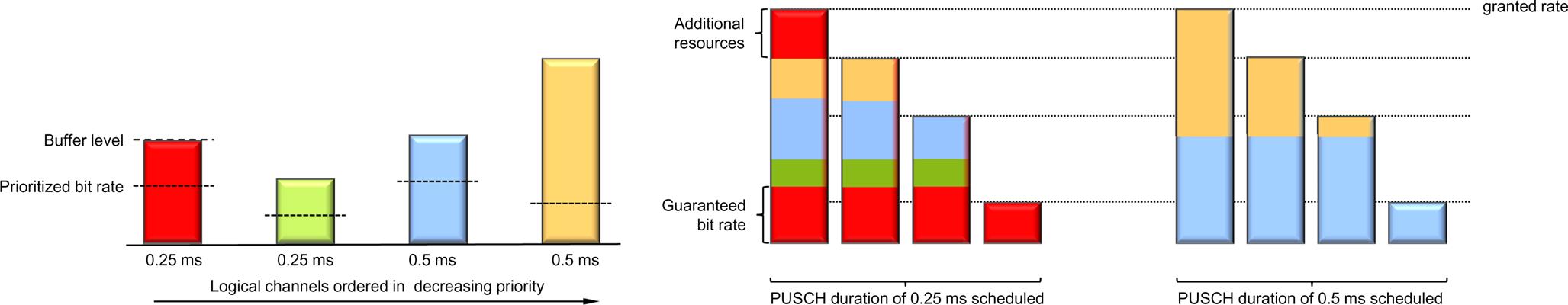
At this point in the process, the set of logical channels from which data are allowed to be transmitted given the current grant is established, based on the mapping-related parameters configured. Multiplexing of the different logical channels also needs to answer the question of how to distribute resources between the logical channels having data to transmit and eligible for transmission. This is done based on a set of priority-related parameters configured for each local channel:
The prioritized bit rate and the bucket size duration together serve a similar purpose as the guaranteed bit rate in LTE but can account for the different transmission durations possible in NR. The product of the prioritized bit rate and the bucket size duration is in essence a bucket of bits that at a minimum should be transmitted for the given logical channel during a certain time. At each transmission instant, the logical channels are served in decreasing priority order, while trying to fulfill the requirement on the minimum number of bits to transmit. Excess capacity when all the logical channels are served up to the bucket size is distributed in strict priority order.
Priority handling and logical channel multiplexing are illustrated in Fig. 14.6.
14.2.2 Scheduling Request
The uplink scheduler needs knowledge of devices with data to transmit and that therefore need to be scheduled. There is no need to provide uplink resources to a device with no data to transmit. Hence, as a minimum, the scheduler needs to know whether the device has data to transmit and should be given a grant. This is known as a scheduling request. Scheduling requests are used for devices not having a valid scheduling grant; devices that have a valid grant provide more detailed scheduling information to the gNB as discussed in the next section.
A scheduling request is a flag, raised by the device to request uplink resources from the uplink scheduler. Since the device requesting resources by definition has no PUSCH resource, the scheduling request is transmitted on the PUCCH using preconfigured and periodically reoccurring PUCCH resources dedicated to the device. With a dedicated scheduling-request mechanism, there is no need to provide the identity of the device requesting to be scheduled as the identity is implicitly known from the resources upon which the request is transmitted. When data with higher priority than already existing in the transmit buffers arrive at the device and the device has no grant and hence cannot transmit the data, the device transmits a scheduling request at the next possible instant and the gNB can assign a grant to the device upon reception of the request (see Fig. 14.7).

This is similar to the approach taken by LTE; however, NR supports configuration of multiple scheduling requests from a single device. A logical channel can be mapped to zero or more scheduling request configurations. This provides the gNB not only with information that there are data awaiting transmission in the device, but also what type of data are awaiting transmission. This is useful information for the gNB given the wider range of traffic types the NR is designed to handle. For example, the gNB may want to schedule a device for transmission of latency-critical information but not for non-latency-critical information.
Each device can be assigned dedicated PUCCH scheduling request resources with a periodicity ranging from every second OFDM symbol to support very latency-critical services up to every 80 ms for low overhead. Only one scheduling request can be transmitted at a given time, that is, in the case of multiple logical channels having data to transmit a reasonable behavior is to trigger the scheduling request corresponding to the highest-priority logical channel. A scheduling request is repeated in subsequent resources, up to a configurable limit, until a grant is received from the gNB. It is also possible to configure a prohibit timer, controlling how often a scheduling request can be transmitted. In the case of multiple scheduling-request resources in a device, both of these configurations are done as per scheduling request resource.
A device which has not been configured with scheduling request resources relies on the random-access mechanism to request resources. This can be used to create a contention-based mechanism for requesting resources. Basically, contention-based designs are suitable for situations where there is a large number of devices in the cell and the traffic intensity, and hence the scheduling intensity, is low. In the case of higher traffic intensities, it is beneficial to set up at least one scheduling request resource for the device.
14.2.3 Buffer Status Reports
Devices that already have a valid grant do not need to request uplink resources. However, to allow the scheduler to determine the amount of resources to grant to each device in the future, information about the buffer situation, discussed in this section, and the power availability, discussed in the next section, is useful. This information is provided to the scheduler as part of the uplink transmission through MAC control elements (see Section 6.4.4.1 for a discussion on MAC control elements and the general structure of a MAC header). The LCID field in one of the MAC subheaders is set to a reserved value indicating the presence of a buffer status report, as illustrated in Fig. 14.8.

From a scheduling perspective, buffer information for each logical channel is beneficial, although this could result in a significant overhead. Logical channels are therefore grouped into up to eight logical-channel groups and the reporting is done per group. The buffer-size field in a buffer-status report indicates the amount of data awaiting transmission across all logical channels in a logical-channel group. Four different formats for buffer status reports are defined, differing in how many logical-channel groups are included in one report and the resolution of the buffer status report. A buffer-status report can be triggered for the following reasons:
- • Arrival of data with higher priority than currently in the transmission buffer—that is, data in a logical-channel group with higher priority than the one currently being transmitted—as this may impact the scheduling decision.
- • Periodically as controlled by a timer.
- • Instead of padding. If the amount of padding required to match the scheduled transport block size is larger than a buffer-status report, a buffer-status report is inserted as it is better to exploit the available payload for useful scheduling information instead of padding if possible.
14.2.4 Power Headroom Reports
In addition to buffer status, the amount of transmission power available in each device is also relevant for the uplink scheduler. There is little reason to schedule a higher data rate than the available transmission power can support. In the downlink, the available power is immediately known to the scheduler as the power amplifier is in the same node as the scheduler. For the uplink, the power availability, or power headroom, needs to be provided to the gNB. Power headroom reports are therefore transmitted from the device to the gNB in a similar way as the buffer-status reports—that is, only when the device is scheduled to transmit on the UL-SCH. A power headroom report can be triggered for the following reasons:
It is also possible to configure a prohibit timer to control the minimum time between two power-headroom reports and thereby the signaling load on the uplink.
There are three different types of power-headroom reports defined in NR, Type 1, Type 2, and Type 3. In the case of carrier aggregation or dual connectivity, multiple power headroom reports can be contained in a single message (MAC control element).
Type 1 power headroom reporting reflects the power headroom assuming PUSCH-only transmission on the carrier. It is valid for a certain component carrier, assuming that the device was scheduled for PUSCH transmission during a certain duration, and includes the power headroom and the corresponding value of the maximum per-carrier transmit power for component carrier c is denoted, PCMAX,c. The value of PCMAX,c is explicitly configured and should hence be known to the gNB, but since it can be separately configured for a normal uplink carrier and a supplementary uplink carrier, both belonging to the same cell (that is, having the same associated downlink component carrier), the gNB needs to know which value the device used and hence which carrier the report belongs to.
It can be noted that the power headroom is not a measure of the difference between the maximum per-carrier transmit power and the actual carrier transmit power. Rather, the power headroom is a measure of the difference between PCMAX,c and the transmit power that would have been used assuming that there would have been no upper limit on the transmit power (see Fig. 14.9). Thus, the power headroom can very well be negative, indicating that the per-carrier transmit power was limited by PCMAX,c at the time of the power headroom reporting—that is, the network has scheduled a higher data rate than the device can support given the available transmission power. As the network knows what modulation-and-coding scheme and resource size the device used for transmission in the time duration to which the power-headroom report corresponds, it can determine the valid combinations of modulation-and-coding scheme and resource size allocation, assuming that the downlink path loss is constant.

Type 1 power headroom can also be reported when there is no actual PUSCH transmission. This can be seen as the power headroom assuming a default transmission configuration corresponding to the minimum possible resource assignment.
Type 2 power headroom reporting is similar to type 1, but assumes simultaneous PUSCH and PUCCH reporting, a feature that is not fully supported in the first release of the NR specifications but planned for finalization in later releases.
Type 3 power headroom reporting is used to handle SRS switching, that is, SRS transmissions on an uplink carrier where the device is not configured to transmit PUSCH. The intention with this report is to be able to evaluate the uplink quality of alternative uplink carries and, if deemed advantageous, (re)configure the device to use this carrier for uplink transmission instead.
Compared to power control, which can operate different power-control processes for different beam-pair links (see Chapter 15), the power-headroom report is per carrier and does not explicitly take beam-based operation into account. One reason is that the network is in control of the beams used for transmission and hence can determine the beam arrangement corresponding to a certain power-headroom report.
14.3 Scheduling and Dynamic TDD
One of the key features of NR is the support for dynamic TDD, where the scheduler dynamically determines the transmission direction. Although the description uses the term dynamic TDD, the framework can in principle be applied to half-duplex operation in general, including half-duplex FDD. Since a half-duplex device cannot transmit and receive simultaneously, there is a need to split the resources between the two directions. As mentioned in Chapter 7 three different signaling mechanisms can provide information to the device on whether the resources are used for uplink or downlink transmission:
The scheduler is responsible for the dynamic signaling for the scheduled device, that is, the first of the three bullets above.
In the case of a device capable of full-duplex operation, the scheduler can schedule uplink and downlink independently of each other and there is limited, if any, need for the uplink and downlink scheduler to coordinate their decisions.
In the case of a half-duplex device, on the other hand, it is up to the scheduler to ensure that a half-duplex device is not requested to simultaneously receive and transmit. If a semi-static uplink–downlink pattern has been configured, the schedulers obviously need to obey this pattern as well as it cannot, for example, schedule an uplink transmission in a slot configured for downlink usage only.
14.4 Transmission Without a Dynamic Grant
Dynamic scheduling, as described above, is the main mode of operation in NR. For each transmission interval, for example, a slot, the scheduler uses control signaling to instruct the device to transmit or receive. It is flexible and can adopt to rapid variations in the traffic behavior, but obviously requires associated control signaling; control signaling that in some situations it is desirable to avoid. NR therefore also supports transmission schemes not relying on dynamic grants.
In the downlink, semi-persistent scheduling is supported where the device is configured with a periodicity of the data transmissions using RRC signaling. Activation of semi-persistent scheduling is done using the PDCCH as for dynamic scheduling but with the CS-RNTI instead of the normal C-RNTI.3 The PDCCH also carries the necessary information in terms of time–frequency resources and other parameters needed in a similar way as dynamic scheduling. The hybrid-ARQ process number is derived from the time when the downlink data transmission starts according to a formula. Upon activation of semi-persistent scheduling, the device receives downlink data transmission periodically according to the RRC-configured periodicity using the transmission parameters indicated on the PDCCH activating the transmission. Hence, control signaling is only used once and the overhead is reduced. After enabling semi-persistent scheduling, the device continues to monitor the set of candidate PDCCHs for uplink and downlink scheduling commands. This is useful in the case that there are occasional transmissions of large amounts of data for which the semi-persistent allocation is not sufficient. It is also used to handle hybrid-ARQ retransmissions which are dynamically scheduled.
In the uplink, two schemes for transmission without a dynamic grant are supported, differing in the ways they are activated (see Fig. 14.10):
- • Configured grant type 1, where an uplink grant is provided by RRC, including activation of the grant; and
- • Configured grant type 2, where the transmission periodicity is provided by RRC and L1/L2 control signaling is used to activate/deactivate the transmission in a similar way as in the downlink case.

The benefits for the two schemes are similar, namely to reduce control signaling overhead and, to some extent, to reduce the latency before uplink data transmission as no scheduling request–grant cycle is needed prior to data transmission.
Type 1 sets all the transmission parameters, including periodicity, time offset, and frequency resources as well as modulation-and-coding scheme of possible uplink transmissions, using RRC signaling. Upon receiving the RRC configuration, the device can start to use the configured grant for transmission in the time instant given by the periodicity and offset. The reason for the offset is to control at what time instants the device is allowed to transmit. There is no notion of activation time in the RRC signaling in general; RRC configurations take effect as soon as they are received correctly. This point in time may vary as it depends on whether RLC retransmissions were needed to deliver the RRC command or not. To avoid this ambiguity, a time offset relative to the SFN is included in the configuration.
Type 2 is similar to downlink semi-persistent scheduling. RRC signaling is used to configure the periodicity, while the transmission parameters are provided as part of the activation using the PDCCH. Upon receiving the activation command, the device transmits according to the preconfigured periodicity if there are data in the buffer. If there are no data to transmit, the device will, similarly to type 1, not transmit anything. Note that no time offset is needed in this case as the activation time is well defined by the PDCCH transmission instant.
The device acknowledges the activation/deactivation of the configured grant type 2 by sending a MAC control element in the uplink. If there are no data awaiting transmission when the activation is received, the network would not know if the absence of transmission is due to the activation command not being received by the device or if it is due to an empty transmission buffer. The acknowledgment helps in resolving this ambiguity.
In both these schemes it is possible to configure multiple devices with overlapping time–frequency resources in the uplink. In this case it is up to the network to differentiate between transmissions from the different devices.
14.5 Discontinuous Reception
Packet-data traffic is often highly bursty, with occasional periods of transmission activity followed by longer periods of silence. From a delay perspective, it is beneficial to monitor the downlink control signaling in each slot (or even more frequently) to receive uplink grants or downlink data transmissions and instantaneously react on changes in the traffic behavior. At the same time this comes at a cost in terms of power consumption at the device; the receiver circuitry in a typical device represents a non-negligible amount of power consumption. To reduce the device power consumption, NR includes mechanisms for discontinuous reception (DRX), following the same framework as in LTE with enhancements to handle multiple numerologies. Bandwidth adaptation and carrier activation are two other examples of power-saving mechanisms.
The basic mechanism for DRX is a configurable DRX cycle in the device. With a DRX cycle configured, the device monitors the downlink control signaling only when active, sleeping with the receiver circuitry switched off the remaining time. This allows for a significant reduction in power consumption: the longer the cycle, the lower the power consumption. Naturally, this implies restrictions to the scheduler as the device can be addressed only when active according to the DRX cycle.
In many situations, if the device has been scheduled and is active with receiving or transmitting data, it is highly likely it will be scheduled again in the near future. One reason could be that it was not possible to transmit all the data in the transmission buffer in using one scheduling occasion and hence additional occasions are needed. Waiting until the next activity period according to the DRX cycle, although possible, would result in additional delays. Hence, to reduce the delays, the device remains in the active state for a certain configurable time after being scheduled. This is implemented by the device (re)starting an inactivity timer every time it is scheduled and remaining awake until the time expires, as illustrated at the top of Fig. 14.11. Due to the fact that NR can handle multiple numerologies, the DRX timers are specified in milliseconds in order not to tie the DRX periodicity to a certain numerology.

Hybrid-ARQ retransmissions are asynchronous in both uplink and downlink. If the device has been scheduled a transmission in the downlink it could not decode, a typical situation is that the gNB retransmits the data at a later time instant, often as soon as possible. Therefore, the DRX functionality has a configurable timer which is started after an erroneously received transport block and used to wake up the device receiver when it is likely for the gNB to schedule a retransmission. The value of the timer is preferably set to match the roundtrip time in the hybrid-ARQ protocol; a roundtrip time that depends on the implementation.
The above mechanism, a (long) DRX cycle in combination with the device remaining awake for some period after being scheduled, is sufficient for most scenarios. However, some services, most notably voice-over-IP, are characterized by periods of regular transmission, followed by periods of no or very little activity. To handle these services, a second short DRX cycle can optionally be used in addition to the long cycle described above. Normally, the device follows the long DRX cycle, but if it has recently been scheduled, it follows a shorter DRX cycle for some time. Handling voice-over-IP in this scenario can be done by setting the short DRX cycle to 20 ms, as the voice codec typically delivers a voice-over-IP packet per 20 ms. The long DRX cycle is then used to handle longer periods of silence between talk spurts.
In addition to the RRC configuration of the DRX parameters, the gNB can terminate an “on duration” and instruct the device to follow the long DRX cycle. This can be used to reduce the device power consumption if the gNB knows that no additional data are awaiting transmission in the downlink and hence there is no need for the device to be active.