
10
using data hubs and data wires
In this third part of the book, you’ll learn how to use data hubs and data wires to create more advanced programs for your robots. For example, you’ll use data hubs and data wires to create programs that display sensor readings on the screen (Chapter 10), do mathematics with the NXT (Chapter 11), or remember things such as high scores of games (Chapter 12).
In earlier chapters you configured each programming block by entering the desired settings in the Configuration Panel. One of the fundamental concepts in this chapter is that blocks can configure each other. For example, one block can instruct a Motor block to run a motor at a certain power level. Blocks transfer information such as the power level using data hubs and data wires. To make this a bit more tangible, think of this as like a person who uses a (wired) phone to ask someone to set the radio to half of its maximum volume, as shown in Figure 10-1. The two people here represent programming blocks. The actual phone is the data hub, and the phone wire is the data wire.
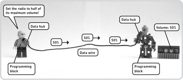
Figure 10-1: You use data hubs (the phones) and a data wire (the phone wire) to carry a value (the radio volume) from one programming block (the person on the left) to the other (the person on the right). The second block uses the value to turn on the radio at the requested volume level.
The “block” on the left basically passes the desired radio volume to the “block” on the right, which can then set the radio to the appropriate volume. For the volume value to move from the first to the second programming block, it goes from the block through a data hub (the phone on the left), through a data wire (the phone wire), and through another data hub (the phone on the right); when it reaches the second block, it specifies its (volume) setting.
To summarize this concept, data wires carry values from one block to another to configure one of this block’s settings. A data hub, which is part of a programming block, allows a block to pass values into the wire (the data hub on the left of Figure 10-1) and retrieve values from it (the data hub on the right of Figure 10-1).
This chapter teaches you how to make programs that use data hubs and data wires. You may find this a bit difficult at first, but as you go through the sample programs and the discoveries, you’ll master all of these programming techniques!
building SmartBot
To make it easier to learn all these new features, you’ll build a small platform with two motors, some sensors, and the NXT, called SmartBot, as shown in Figure 10-2. This robot will help you better understand how the advanced programs that you’ll make really work.
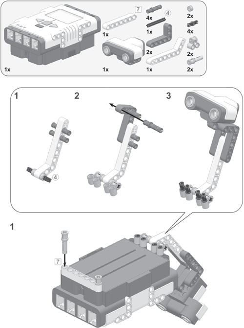
Now build SmartBot by following the instructions on the next few pages, but first select the required pieces, as shown in Figure 10-3.
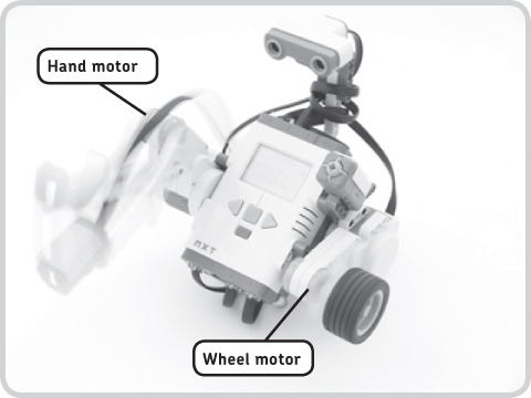
Figure 10-2: You’ll use the SmartBot robot to learn many new programming techniques. I’ll refer to the motor with the Color Sensor as the Hand motor and the one with the wheel as the Wheel motor.

Figure 10-3: The required pieces to build SmartBot


a program to get started with data wires
To see how data hubs and data wires work, you’ll create a small program that will make the SmartBot play a sound and then make the Hand motor rotate for three seconds. The motor’s power level (and thus its speed) will respond to what the Ultrasonic Sensor sees: If the sensor sees something 43 cm away, the motor’s power level will be 43 for three seconds; if the sensor reads 15 cm, the motor power will be 15; and so on. For example, if you keep a book close to the sensor and run the program, the hand should go up and down slowly, but move faster if you run the program again with the book farther away.
To accomplish these actions, you’ll use the Ultrasonic Sensor block. You’ll learn more about this block later, but for now just know that you use it to poll the sensor. Create the Smart-Intro program as shown in Figures 10-4 through 10-6, and then run the program to see how it works.

Figure 10-4: Step 1: Place all the necessary blocks for the Smart-Intro program on the Work Area, and configure them as shown here.

Figure 10-5: Step 2: Open the blocks’ data hubs by clicking the tabs at the lower-left edge of the block. You should already see a small data hub just below the Ultrasonic Sensor block, but you can open the complete data hub by clicking the same tab.

Figure 10-6: Step 3: Create and connect the yellow wire as shown here. The yellow line is the data wire.
Download the program to SmartBot, and run it while keeping a book about 20 cm (8 inches) away from the Ultrasonic Sensor. Next, run the program again with the book about twice as far from the robot. You should notice that each time you run the program, the Hand motor turns at a different speed.
understanding the sample program
Congratulations! You’ve just created your first program with data wires. Now you’ll learn exactly how your program works by analyzing the function of each block.
The first Sound block simply plays a sound. Once the sound finishes playing, the Ultrasonic Sensor block polls the sensor once, resulting in a reading of, say, 35 cm. The yellow data wire then carries the sensor measurement to the other end of the wire to the Motor block, which then makes the Hand motor turn for three seconds, as specified in its Configuration Panel. The motor power (and thus its speed) depends on the value carried by the data wire; it’s 35 in this case. Figure 10-7 shows an overview of what happens.

Figure 10-7: An overview of the Smart-Intro program. The Ultrasonic Sensor block polls the sensor and sends the sensor value through a data wire to the Motor block, which uses this value to set the motor speed.
how do data hubs and data wires work?
You’ll now analyze some of the new features that you used in the program you just made. As you can see, you use a data wire to carry information between blocks. In the example program, the yellow data wire carries the sensor value to the Motor block to set the motor’s power level.
You created the data wire by first clicking one of the data plugs on the data hub of the Ultrasonic Sensor block. Each data plug carries out a different value, but you connected your data wire to the Distance data plug, because you wanted to know the measured distance. Next, you connected the other end of the wire to the Power data plug on the hub of the Motor block. As a result, you actually reconfigured the Power setting of this block, and the motor moved at a speed based on the sensor reading.
You’ll now take a more detailed look at the data hub. Open a new program, pick a Motor block from the Programming Palette, and place it on the Work Area. Then, open the block’s data hub, as shown in Figure 10-8.
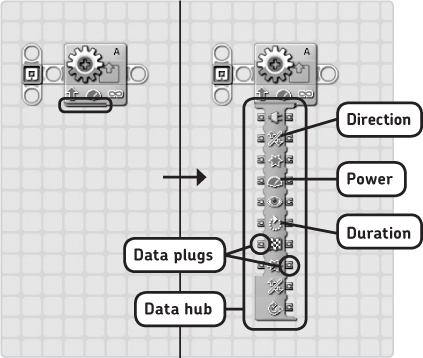
Figure 10-8: To open a block’s data hub, click the tab at the lower-left edge of the block. To close the hub, click the tab again. Move your mouse pointer over the data plugs to figure out what each plug stands for. (I’ve shown only a few examples here.)
As you mouse over the various plugs on the data hub, you should see which setting is reconfigured when you connect a wire to this plug. For example, as shown in Figure 10-8, you’ll see plugs for Direction, Power, and Duration. You’ll also find these terms on the block’s Configuration Panel. In other words, when wiring data wires into a block’s data hub, you’re actually reconfiguring the block’s settings as if modifying the settings in the Configuration Panel.
creating a second example program with data wires and data hubs
Now you’ll create a program to make the SmartBot’s motor accelerate. It will start out slowly and increase its speed until it reaches the maximum power level.
To make this program, you place a Motor block that makes the motor turn for half a second inside a Loop block. Because the Motor block is inside the loop, the motor keeps spinning. You’ll also use a new feature of the Loop block that makes it count the number of times it has repeated the Motor block inside it, called the loop count.
Because the Motor block keeps looping, the loop count increases over time, and you use this value as an input for the motor power. When you start the program, the loop count is 0, which makes the motor run at zero speed (it stands still) for half a second (as specified by the Duration setting). When the Loop block returns to the beginning, it repeats the Motor block; the loop count increases to 1, and therefore the motor’s power level is 1. When it repeats, the motor speed is 2, and so on. Follow the instructions in Figures 10-9 and 10-10 to create the Smart-Accelerate program.
Download this program to your robot, and run it. If you configured everything correctly, the SmartBot’s hand should start moving slowly, and as time passes, the Hand motor’s speed should increase. The hand should stop accelerating when the loop count exceeds 100, because 100 is the motor’s maximum power level.

Figure 10-9: Step 1: Place and configure the two blocks as shown here. Note that the Counter setting is checked in the Loop block, which opens a little plug on the left side of the Loop block.

Figure 10-10: Step 2: Open the Motor block’s data hub, and connect the data wire to the plugs as shown here.
using data plugs: input and output
As you saw earlier, you connect data wires to data plugs on data hubs. The hubs contain two types of plugs, as shown in Figure 10-11: output plugs (on the right side) and input plugs (on the left side). Output plugs carry out a value and pass it to a data wire. For example, the Distance plug on the Ultrasonic Sensor block carries out the measured distance value. Input plugs retrieve the value from the data wire and pass it to the block it connects to so that the value can be used to reconfigure one of the block’s settings. For example, you used the Power plug as an input plug.
Generally, a data wire carries information from an output plug of one block to an input plug of another block.
NOTE The Compare setting in the Ultrasonic Sensor block’s Configuration Panel controls how the Yes/No output plug works. However, when using the Ultrasonic Sensor block just to poll the sensor as you did previously, you’re only using the Distance plug of this block, meaning that you don’t have to configure the Compare setting. (You’ll learn how to use this setting in “The Logic Data Wire” on page 163.)

Figure 10-11: Input and output plugs on a data hub. The data wire carries information from an output plug to an input plug of another block.
block configurations when using data wires
When using blocks with data wires, what happens to the settings you configured in the Configuration Panel? In the two sample programs, you had the Motor block run a motor at a power level specified by a data wire, even though the Motor block’s Power was set to 75 (Figure 10-12).
As a general rule, the data wire input overrides the setting specified in the Configuration Panel, and the setting in the Configuration Panel is ignored, as illustrated in Figure 10-12. All other settings that do not conflict with a data wire are in effect, as specified in the Configuration Panel. For example, the block here will make the motor turn forward because the Configuration Panel says so.

Figure 10-12: A Configuration block’s setting is ignored when a data wire defines the same setting; the block will use the data wire’s value.
deleting data wires
To delete a data wire, follow the instructions shown in Figure 10-13.
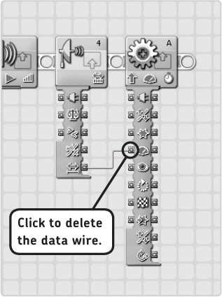
Figure 10-13: To delete a data wire that connects two blocks, click the data plug on the right end of the wire. If this doesn’t work, you should be able to remove it by clicking the wire and then pressing the DELETE key. Before you press this key, though, make sure that no block is selected, or you’ll delete it with the data wire.
Difficulty: Easy
Create the program shown in Figure 10-14. The Display block shown in the figure will display a circle in the middle of the NXT screen. You want the circle to grow bigger as you wait, so the Radius setting should increase over time. The program here is incomplete, because a data hub and a data wire are missing. Can you open the data hub and connect the data wire to finish this program?
HINT Look for the Radius input plug.

Figure 10-14: The incomplete program for Discovery #47. Can you complete it by connecting a data wire appropriately?
Difficulty: Medium
The Smart-Intro program polled the Ultrasonic Sensor once and used the sensor value to set the speed of the Hand motor. You can modify this program so that the motor speed is continuously updated with a new sensor reading as follows:
1. Remove the Sound block.
2. Set the Motor block’s Duration setting to Unlimited.
3. Place the two remaining blocks in a Loop block configured to loop forever. If the data wire breaks as you do so, reconnect it.
Now as the program runs, move the SmartBot back and forth near a wall so that the Ultrasonic Sensor constantly measures a different distance. What happens to the motor speed? Can you figure out why this happens?
sensor blocks
In Chapters 6 and 7 you learned to work with sensors by creating programs with the Wait, Loop, and Switch blocks. The final way to poll sensors is with Sensor blocks, as shown in Figure 10-15. These blocks are useful if you want to retrieve a sensor value and transfer it to another block with a data wire, as you saw with the Smart-Intro program.
There’s a Sensor block for each sensor, including some sensors not found in the LEGO MINDSTORMS NXT 2.0 robotics kit. In the example programs so far, you’ve used the Ultrasonic Sensor block. Sensor blocks are of no use on their own; they must be connected to another block with a data wire in order to function.
configuring a sensor block
Configuring a Sensor block is very much like configuring a Wait, Loop, or Switch block, except that the Sensor blocks do nothing with sensor measurements themselves. Sensor blocks simply transmit sensor readings to other blocks with data wires. In addition to polling sensors, Sensor blocks can also compare a measured sensor value with a trigger value. Generally, these blocks have two output plugs. One plug outputs the sensor measurement (like the Distance plug in the Ultrasonic Sensor block); the other, the Yes/No plug, outputs the result of the comparison, as you’ll learn in “Seeing a Logic Data Wire in Action” on page 164.
configuring a touch sensor block
The Touch Sensor block outputs its sensor value with the Logical Number plug, where a value of 1 represents pressed, and 0 means released. However, when you use this block, you’ll more frequently use its Yes/No output plug, discussed in “Seeing a Logic Data Wire in Action” on page 164.
configuring a color sensor block
As mentioned previously, the Color Sensor can identify six different colors. The Detected Color plug on the Color Sensor block outputs a number between 1 and 6, with each number representing a particular color: black = 1, blue = 2, green = 3, yellow = 4, red = 5, and white = 6. (In Chapter 11 you’ll create some programs that use this feature.)
Recall that the Color Sensor can function as a Light Sensor. Not surprisingly, you can use the Light Sensor’s value in a program by selecting Light Sensor in the Action box on the Color Sensor block’s Configuration Panel. Once configured in this way, when you subsequently connect a data wire to the Detected Color plug, it should carry out a value from 0 to 100, based on the brightness of the detected light (100 is brightest).
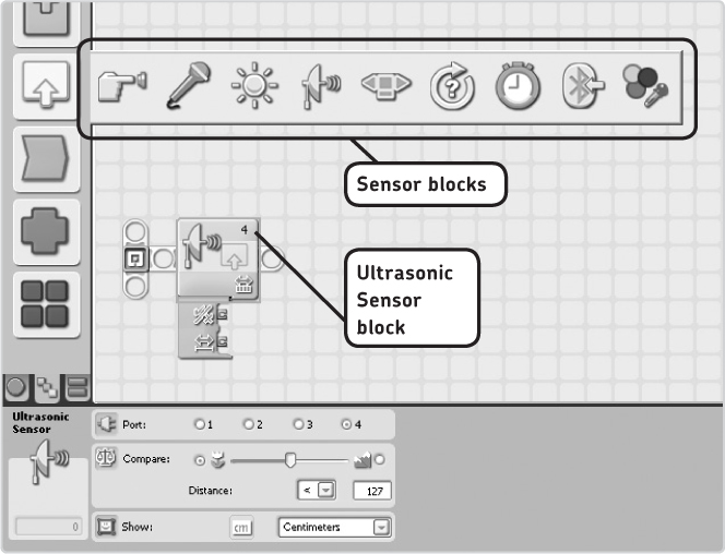
Figure 10-15: You can find a Sensor block for each sensor on the Complete Palette.
configuring a rotation sensor block
In Chapter 7 you learned that each motor contains a Rotation Sensor, which tells you how many degrees a motor has turned since you started the program. The Degrees plug on the Rotation Sensor block’s data hub outputs this number of degrees. If you rotate the motor backward (see Figure 7-20), the output value will be negative.
data wire types
Data wires carry information between blocks. So far you’ve used data wires to transfer numerical values only, but there are three types of data wires: Number, Logic, and Text data wires. Each type of data wire carries a specific type of information (numerical, logic, or text values), and each type has its own color, as shown in Figure 10-16.
the number data wire
The Number data wire (yellow) carries numeric information that may include whole numbers (such as 0, 15, or 1427), numbers with decimals (such as 0.1 or 73.14), and negative numbers (such as -14 or -31.47).
Examples of information carried by Number data wires are Ultrasonic Sensor readings and loop counts.
the logic data wire
The Logic data wire (green) can carry only two values: true or false. These wires are often used to define settings of a block that can have only two values, such as the turn direction of an NXT motor. For example, a motor will spin forward when a Logic data wire with the value true is connected to the Direction plug of a Motor block. Consequently, it spins backward when the Logic data wire value is false.

Figure 10-16: Examples of three types of values. Each value type is carried by its own data wire, as you’ll learn in a moment. The last data wire here isn’t functional, and it carries no information: The robot’s last question requires a numerical answer, but Mike replied with a sentence, which would require a Text data wire. This mismatch results in a broken data wire, because the given information cannot be used.
seeing a logic data wire in action
You’ll now create a program to see the functionality of the Logic data wire and the Compare function of the Ultrasonic Sensor block in action. This program will make SmartBot’s Wheel motor spin forward as long as the Ultrasonic Sensor sees something closer than 40 cm and spin backward when this is not the case. The required input for the motor’s Direction setting is a Logic data wire (true is forward, and false is backward). Therefore, you’ll make a connection to a data plug on the Ultrasonic Sensor block that sends out a logic value using the Yes/No output plug. This plug will output a logic value (either true or false), based on the result of the Compare box in the Configuration panel. The Ultrasonic Sensor block will check to see whether the sensor reading is smaller than the trigger value (40 cm). If it is, the result is true; if not, the output value is false.
Now create the Smart-LogicWire program as shown in Figure 10-17.
NOTE Because you’re not specifying the motor speed with a data wire, the motor power is 75 no matter which direction the motor spins, as set in the Configuration Panel.
Once you’ve finished creating this program, download it to your robot, and notice how the motor direction flips as you move your hand closer to or farther from the sensor.
the text data wire
The Text data wire (orange) carries text between blocks to, for example, the data hub of a Display block so that it appears on the NXT screen. This text can be a word, like Hello, as well as sentences like My name is Mike.
displaying values with the number to text block
By entering a text line in the Configuration Panel, you can use Display blocks to show a text line on the NXT screen. You can also use a Text data wire to submit text to a block.
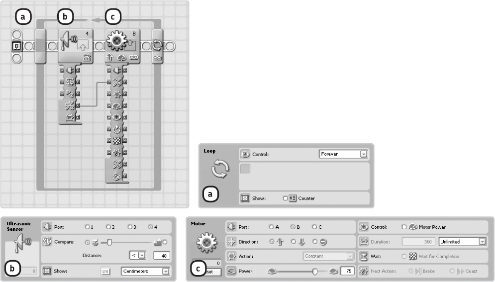
Figure 10-17: The configuration of the Smart-LogicWire program. The green Logic data wire connects the result of the comparison of the Ultrasonic Sensor block to the Direction plug on the Motor block. In this particular setup, the Sensor block checks to see whether the sensor reading is smaller than the trigger value, but you could also make it look for a value bigger than the trigger point. If you do, the result will be true if the sensor reading is greater than 40.
You’ll now make a program that continuously displays the Ultrasonic Sensor reading on the NXT screen. To do so, you use the Ultrasonic Sensor block to find the sensor value. You have a problem now, though, because you cannot use the Display block to display values from Number data wires. Therefore, you’ll have to convert the numeric sensor reading into something that the Display block does accept: text.
The Number to Text block can do this for you. On the data hub’s left side, it takes input from a Number data wire, such as a wire carrying a sensor value. On the right side, it outputs a Text data wire, which contains the same number, except in a format that the Display block can handle. You can see the Number to Text block in Figure 10-18, which also shows you how to make the Smart-TextWire program.

Figure 10-18: The configurations of the blocks in the Smart-TextWire program. You can find the Number to Text block between the Advanced programming blocks. Notice that the Display block (e) is configured to display the Mindstorms NXT text line. However, the program ignores this setting, because you also use a Text data wire to specify what should be displayed.
NOTE When using a Sensor block only to perform a sensor measurement, you don’t need to configure the block’s Compare setting since you won’t be using the result of this comparison.
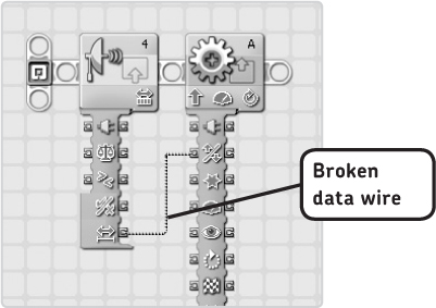
Figure 10-19: If you try to connect a data wire of a certain type (like a Number data wire) to an input plug on another block that doesn’t accept this type, a broken data wire is displayed. The example shown here tells you that you can’t connect the Ultrasonic Sensor reading (a number value) to the Direction plug (a logic value) of a Motor block.
the broken data wire
The broken data wire (gray) carries no information. When such a wire shows up, you know that you’ve made a mistake when making the data wire connection. The mistake can have several causes, as you’ll learn in this and in the “Multiple Data Wire Connections” section. You’ll have to delete this broken wire and reconnect it appropriately, or you won’t be able to transfer the program to the NXT.
When you begin creating a data wire on a block’s output plug, the NXT-G software automatically chooses a color for the wire, depending on the plug you clicked. For example, if you clicked the Ultrasonic Sensor block’s Distance plug, you’d see a yellow wire because the distance value is a number. Because this is a number, you have to connect it to an input plug on another block that accepts Number data wires, like the Power plug on a Motor block.
If you connect the yellow data wire (from the Distance plug) to a plug that cannot handle Number data wires, a broken wire shows up, indicating that the connection isn’t right, as shown in Figure 10-19. (In “Using Help for Data Plugs” on page 168, you’ll learn how to find the right data wire for each plug on a data hub.)
NOTE When you try to send a program with a broken data wire in it to the NXT, you’ll get an error message. The solution is to delete any broken data wire and reconnect it properly, as discussed in “The Broken Data Wire” and “Multiple Data Wire Connections.”
multiple data wire connections
So far, you’ve used only one data wire connection per block, but you can use more data plugs on a single block. You can connect more than one data wire to a single block in several ways, but not every way to connect them results in a working program, as you’ll learn in this section.
connecting multiple wires to different plugs
You can use multiple input plugs on a single block to reconfigure more than just one setting of a block with a data wire. For instance, you can control both the Power and Direction settings of a Motor block with data wires (using one wire for each setting).
In the same way, you can use multiple output plugs on a single block. For example, you can use the Ultrasonic Sensor block to poll a sensor (a data wire carries the sensor value) and compare it to the trigger value (another data wire carries a true or false value).
To illustrate this functionality, you’ll expand the Smart-LogicWire program (Figure 10-17) by adding a Number data wire, as shown in Figure 10-20.

Figure 10-20: You can connect multiple data wires to a block. Here, SmartBot’s Wheel motor rotates forward when the sensor reading is less than 40 cm, and backward otherwise. The actual sensor measurement defines the speed at which the motor turns.
connecting multiple wires to one data plug
You can use a single output plug to send information to more than one block, as shown on the left of Figure 10-21, but not the reverse: You cannot connect more than one wire to a single input plug since then the block would not know which wire to take as the input. If you try to make such a connection, a broken data wire will show up, as shown on the right of Figure 10-21. You can delete broken wires just like other data wires (Figure 10-13).
using settings with both input and output plugs
Some items on a data hub have both input and output plugs, as shown on the left of Figure 10-22. As you’ve learned, the input plug uses a data wire’s value to reconfigure one of the block’s settings. For example, you can use a data wire to set the Action setting of the Color Lamp block.
This Action setting also has an output plug on the right side, which will output the same value as the input value on the left side. Basically, the Color Lamp block on the left of Figure 10-22 takes input from the wire on the left side and passes that value to the next block so that the information can be used again. If, however, there is no input on the left, there is no information to pass through, so the wire will show up as a broken data wire (on the right of Figure 10-22).

Figure 10-21: A single output plug can transfer information to inputs on multiple blocks (shown on the left). When you run this program while the Touch Sensor is pressed, the Color Lamp is switched on, and the motor rotates forward. It is impossible to connect multiple data wires to one input plug (shown on the right).

Figure 10-22: When an input plug has a corresponding output plug, the value received by the input is passed on to the next block with no change (shown on the left). If there is no value to pass on, a broken wire is displayed (shown on the right).
using help for data plugs
When creating programs, you may want to use a block’s data plug that isn’t discussed in this book. If you do, you can find information about data plugs specific to each programming block in the help section of the software. (To access it, click more help in the Little Help Window at the bottom right of the software screen, and after it opens, use the menu on the left to find information on a programming block.)
For example, when you open the help file for the Motor block by clicking the block’s name in the menu on the left, you’ll first see some general information about the block and its functions. As you scroll down on the page, you’ll see a table with the data hub characteristics, a portion of which is shown in Figure 10-23. By looking at this table, you’ll learn how to properly use the functions of each programming block and its data plugs.

Figure 10-23: A few data hub characteristics of the Motor block
The table shown in Figure 10-23 contains specific information about each data plug, including the data wire type (“Data Type”) that should be connected to the plug, the range of possible values for the plug for the block to function as expected (“Possible Range”), what each value means (“What the Values Mean”), and when a data wire is ignored by a block (“This Plug Is Ignored When . . .”).
You’ll now look at the Direction plug. As you’ve learned (and as you can see in Figure 10-23), you can only connect a green Logic data wire to the Direction plug. You also see that a value of true will make the motor spin forward, while false will make the motor rotate backward. Finally, you can see that when a data wire is connected to this plug, it is never ignored. Using this method, you’ll be able to find information about each block’s data hub.
Difficulty: Easy
Create the program shown in Figure 10-24. Your goal is to finish the program to display an image somewhere on the screen (aim in the File list), depending on the reading from the Wheel motor’s Rotation Sensor. The more the motor has turned, the farther the image should move to the right. Use the Display block’s help file to find out which data plug you must use in order to set the horizontal position of the image. Now connect a data wire that will make the program work as described.
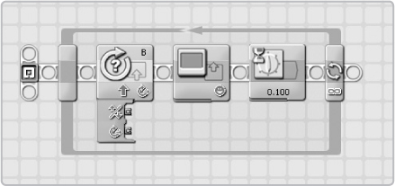
Figure 10-24: A starting point for the program in Discovery #53
tips for managing data wires
Now that you’ve learned how data hubs and data wires work, you can use them in your programs. But, as you make larger programs, it can get difficult to keep your programs organized and understandable, especially when you use a lot of data wires. The following tips will help you to keep your programs clean and readable.
hiding unused data plugs
You can hide unused data plugs on the data hub by clicking the tab at the lower-left edge of a block, as shown in Figure 10-25. To redisplay them, click the tab again. When creating programs, you’ll first open the complete data hub, and then once you’ve connected the desired data wires, you can hide the other plugs.
NOTE From now on in this book, I’ll hide unused data plugs in programs to make the programs more readable.
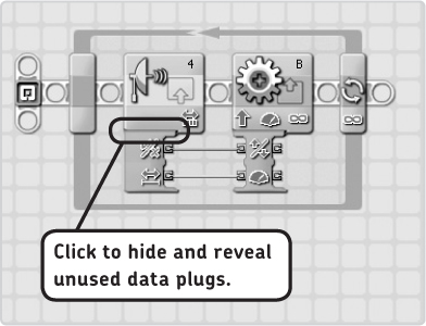
Figure 10-25: Hiding unused data plugs will make programs more compact and understandable.
using data wires across your program
When configuring programs with data wires, you don’t have to connect a block to the one right next to it; you can connect blocks when there are other blocks in between, as shown in Figure 10-26.
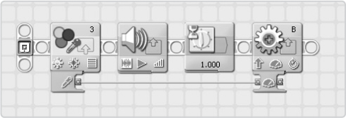
Figure 10-26: Data wires allow you to connect blocks spread over your program, as shown here. The connected blocks do not have to be right next to each other.
further exploration
In this chapter, you learned how to create programs using the features of data wires. Most of the programs you’ve made so far with data wires are fairly small, and data wires may not seem very useful yet. However, data wires are essential to making advanced programs for your NXT robots. In Chapter 11, you’ll learn a few new ways to use data wires beyond simply controlling motor speeds and displaying sensor readings on the robot’s screen.
The following discoveries will let you practice the programming skills you gained in this chapter. Post your solution to these discoveries to the companion website at http://www.discovery.laurensvalk.com/ so that your fellow book readers can see what you’ve made!