
CHAPTER 18
Using Layers, Line Fonts, and Colors
IN THIS CHAPTER
Specifying line format settings
Hiding edges in drawing views
Using drawing display tools tutorial
AutoCAD has left its mark on CAD users of all kinds in the form of the default expectations users have about CAD software. A few common expectations are that layers, the Command Line, and paper space/model space need to exist in order for graphical software to be considered CAD, and printing should be really difficult.
When former AutoCAD users make the switch to SolidWorks, the questions start: Where is the Command Line? How do I put parts on layers? How do I change the background color to black? And my personal favorite, Where is the zero-radius trim?
This chapter addresses AutoCAD-like functions in the SolidWorks drawing environment. The goal is not to make the functions look or work or compare in any way to AutoCAD, but to simply make them useful in the context of the SolidWorks software. It is never productive to try to use SolidWorks as if it were AutoCAD. If you are making the transition, you will be much further ahead if you just embrace SolidWorks for what it is, and accept that it does not work like AutoCAD. You will be even further ahead if you do not assume that AutoCAD functionality is universal.
Controlling Layers
![]() Layers are only available in SolidWorks drawing documents, not in 3D modeling or even sketching at all. Even in drawings, layers do not see a lot of use. This is not to say that they serve no purpose, just that the software does not depend on them.
Layers are only available in SolidWorks drawing documents, not in 3D modeling or even sketching at all. Even in drawings, layers do not see a lot of use. This is not to say that they serve no purpose, just that the software does not depend on them.
Working with layers in imported 2D data
When you import data through DXF (Data eXchange Format) or DWG format files, the layers that exist in the original data are brought forward into SolidWorks, and you can use them in a similar way to the original AutoCAD usage. For example, you can turn layers on or off (visible or hidden), and you can change layer names, descriptions, color, line thickness, and line style.
The way you intend to use the imported data determines how you should open the file. If you only intend to view and print the drawing, then I would suggest using DraftSight, a free download from the Dassault Systèmes or SolidWorks Web sites, or the DWG Editor, which is installed with SolidWorks and enables you to do much of what you can do with basic AutoCAD. These tools offer a familiar interface for the AutoCAD user.
If you need to integrate data from the imported document into a native SolidWorks drawing, you can open the DWG file from the normal Open dialog box in SolidWorks.
Tip
If you want to make a 3D part from the 2D data in the DWG file, you may want to import the drawing into the part sketch environment. This usually leads to some speed issues. If you prefer, sketch entities can also be copied from the drawing to the model sketch. You can even copy entities from DWG Editor to the SolidWorks sketch. The sketch needs to be open in order to paste the sketch entities. In the case where imported 2D data is brought into the model sketch, you lose all the layer information because part and assembly documents do not allow layers.
The colors assigned to layers in data coming from AutoCAD are often based on a black background, and so they can be difficult to see on a white background. The two ways of dealing with this are to change the SolidWorks drawing sheet color to something dark or to change the individual layer colors to something dark. Either method is easy, although if you have to send the 2D data back to its source, it may be best to temporarily change the drawing sheet color.
Figure 18.1 shows the layer interface with an imported drawing in the background. To open the Layers dialog box, click the Layer Properties button, which is found on both the Layer and Line Format toolbars.
FIGURE 18.1 The Layers dialog box and the Layer toolbar
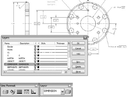
Be aware that many items in an imported drawing may come into SolidWorks as blocks. These items may need to be exploded before you can work with them. This is often the case with the drawing border, title block, or format. To explode a block, right-click on the block and choose Explode.
Working with layers on the sheet format
One of the most obvious uses of layers is for the drawing border sketch lines on the sheet format. The sketch lines used to create the border often have a heavier line weight and a different color that easily distinguishes them from model geometry.
You can assign layers in one of three ways:
- Select existing items, and then select a layer from the drop-down list on the Layer toolbar.
- Set the active layer and create new items.
- While creating items such as sketch entities and annotations, select the layer for the new entity directly from the PropertyManager.
To set a layer to the active layer, double-click it from the Layers dialog box, as shown in Figure 18.1, or change it from the drop-down list on the Layer toolbar. When you assign an active layer, other newly created entities are also placed on the layer, not just sketch entities. Symbols, annotations, blocks, and other elements can also be put onto layers. If you are not particular about the layering scheme on a drawing, then it may be advisable to set the active layer to None, which is a valid option in the Layer toolbar drop-down list.
When you create a new layer in SolidWorks, the new layer becomes the active layer, and any new items that are added are automatically placed on that layer.
Another option when building a sheet format, or any other drawing function that requires sketching, is to use a special layer for construction geometry. This enables you to hide the layer when it is not being used, but it still maintains its relations. Hidden layers can be used in several other ways (for example, as standard notes on the drawing), and they can be easily turned on or off.
Adding dimensions and notes to layers
SolidWorks drawings have a tendency to be drab black-and-white drawings in contrast to AutoCAD drawings, which often seem to take on a plethora of contrasting colors. Drawings are often a little easier to comprehend when different types of items are colored differently, but to do this effectively, you must apply the coloring scheme consistently. Dimensions and annotations can also be placed on layers in the three ways described in the previous section (active layer, from the PropertyManager during creation, and through the drop-down list on the Layer toolbar). However, the line styles do not affect dimensions and notes, only the color and visibility settings.
Working with components on layers
Assembly drawings probably suffer the most from the monochromatic nature of most SolidWorks drawings because individual components can be difficult to identify when everything is the same color. This is why SolidWorks users typically color parts in the shaded model assembly window. It only makes sense that they would want to do the same thing on the drawing.
Using assembly colors on drawings
Starting in SolidWorks 2011, you can now use assembly part colors on drawings. This is a document-specific setting, so it will only apply to the documents where you want it to apply, not to all drawings. If you use this setting, you may also need to be more careful in how you choose part colors in your assemblies. You will generally want to choose darker and more saturated colors, and avoid the yellows, grays, and light colors that will not contrast with the white or gray color of the default SolidWorks drawing sheet.
You can find the setting to use assembly part color on your drawing at Tools ![]() Options
Options ![]() Document Properties
Document Properties ![]() Detailing
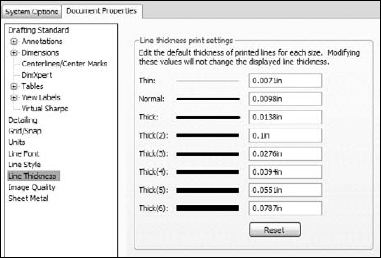
Detailing ![]() Use Model Color for HLR/HLV in Drawings. HLR stands for hidden lines removed, and HLV stands for hidden lines visible. These are the two wireframe display modes that are most frequently used on drawings. Of course, another way to display part color on drawings is to use shaded views, but for traditional drawings, shaded views are often considered nonstandard. Figure 18.2 shows the setting in the Document Properties dialog box.
Use Model Color for HLR/HLV in Drawings. HLR stands for hidden lines removed, and HLV stands for hidden lines visible. These are the two wireframe display modes that are most frequently used on drawings. Of course, another way to display part color on drawings is to use shaded views, but for traditional drawings, shaded views are often considered nonstandard. Figure 18.2 shows the setting in the Document Properties dialog box.
FIGURE 18.2 Using assembly part colors on your drawing

The setting mentioned for shaded drawing views is available by selecting the view on the drawing, and clicking the Shaded display style toolbar icon from the Heads Up View toolbar on the drawing, or from wherever the View toolbar is displayed. You could do the same thing by selecting the view and then choosing View ![]() Display
Display ![]() Shaded or Shaded With Edges.
Shaded or Shaded With Edges.
Using assembly parts on layers
Another option to display the components of an assembly in different colors while using a wireframe display mode that wouldn't rely on colors assigned to parts in the assembly is to use the Component Line Font options. (Line Fonts are covered in the section “Controlling Line Format.”) The Component Line Font dialog box contains a Layer setting, which you can use to put a part on a layer. If the layer is set up with a color, then the part displays with that color in all views of the drawing or in just the current view, depending on your settings. It does take a little time to set up the individual layers for each part and then to set the parts to the layers.
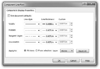
You can access the Component Line Font dialog box by right-clicking a component in a drawing view. The Component Line Font dialog box is shown in Figure 18.3.
FIGURE 18.3 The Component Line Font dialog box

In normal use, the Use document defaults option is selected and all the settings in the dialog box are grayed out. To gain access to these settings, you must deselect the Use document defaults option, as shown in Figure 18.3.
Controlling Line Format
![]() The Line Format toolbar contains the Layer tool and four additional tools that control lines: Line Color, Line Thickness, Line Style, and Color Display Mode. These settings can be controlled separately from layers; therefore, they can be used in model sketches as well as on drawings. In the model, the line font can only be displayed for inactive sketches. Any sketch that is both closed and shown can be displayed with the Line Format settings.
The Line Format toolbar contains the Layer tool and four additional tools that control lines: Line Color, Line Thickness, Line Style, and Color Display Mode. These settings can be controlled separately from layers; therefore, they can be used in model sketches as well as on drawings. In the model, the line font can only be displayed for inactive sketches. Any sketch that is both closed and shown can be displayed with the Line Format settings.
Cross-Reference
For more information on using line styles in the model, see Chapter 6.
Figure 18.4 shows the Line Format toolbar along with the interfaces for Line Color, Line Thickness, and Line Style.
FIGURE 18.4 The Line Format toolbar and related interface options

Note
The term line font refers to a combination of style, end cap, and thickness. To set line fonts, choose Tools ![]() Options
Options ![]() Document Properties
Document Properties ![]() Line Font and use the document-specific settings.
Line Font and use the document-specific settings.
Using the Line Format settings
You can specify the Line Format settings using two different methods. In the first method, you can set them with nothing selected, in which case they function like System Options (the new setting takes effect for all documents that are opened on the current computer). In the second method, if they are set with sketch entities or edges selected, then the settings apply only to the selected entities.
Caution
If you change these settings with nothing selected, then the Line Format settings for color, thickness, and style function as system options.
Setting the End Cap Style
Another option for the Line Font settings is the End Cap Style. This offers an important option, especially for thick lines. The three options are flat, round, and square. Of these, the square style is usually most appropriate. In the past, flat was the default style. To find this setting, choose Tools ![]() Options
Options ![]() Document Properties
Document Properties ![]() Line Font. You may want to change this setting and update your drawing template files.
Line Font. You may want to change this setting and update your drawing template files.
Figure 18.5 shows the difference between the three options of End Cap Style.
FIGURE 18.5 The End Cap Style setting options
Notice the small notches at the sharp corners of the style to the left, which is the flat style. These can be very distracting on a drawing, and in my opinion they don't look very professional. This notched effect is most pronounced on thicker lines.
Setting the line thickness
The Line Thickness settings are Default, Custom, and eight width settings. Interestingly, the different thicknesses are named in the interface where you set the actual thicknesses, but not in the interface where you set lines to thicknesses. Figure 18.6 shows the Line Thickness page (Tools ![]() Options
Options ![]() Document Properties
Document Properties ![]() Line Thickness).
Line Thickness).
FIGURE 18.6 The Line Thickness settings in Tools ![]() Options
Options
The way the line thickness is shown in the drawing does not have anything to do with the numerical width that is assigned to it. For example, in Figure 18.6, notice that Thick(2) is set to 0.1 inch, which is much wider than Thick(3), which, in this case, is set to 0.0275 inch. Changing the numbers only affects printed line thickness; it does not affect the display at all.
Caution
The Line Thickness settings are document options, not system options. As a result, two drawings with the same line type assignments may have different numerical widths; thus, the two drawings would print differently on the same computer. This can be a benefit or a trap, so pay attention when you change the settings.
Setting the line style
You can create custom line styles using the syntax shown on the Line Style page (Tools ![]() Options
Options ![]() Document Properties
Document Properties ![]() Line Style). This is a document-specific setting; therefore, if you make a custom line style and want to use it in another document, you have to save it out (as a *.sldlin file) and load it into the other document. Also, if you save your templates with this line style loaded, then you will not have to load the styles for any document made from that template.
Line Style). This is a document-specific setting; therefore, if you make a custom line style and want to use it in another document, you have to save it out (as a *.sldlin file) and load it into the other document. Also, if you save your templates with this line style loaded, then you will not have to load the styles for any document made from that template.
Changing the Color Display mode
![]() Color Display mode toggles between the display of assigned colors and standard sketch state colors. This is primarily used in drawings when you are making sketches where sketch relations are important. This setting is used to control the display of sketch entities only.
Color Display mode toggles between the display of assigned colors and standard sketch state colors. This is primarily used in drawings when you are making sketches where sketch relations are important. This setting is used to control the display of sketch entities only.
Hiding and Showing Edges
![]() Sometimes, for illustrative purposes, it is desirable to hide certain edges in drawing views. The Hide/Show Edge toolbar button is on the Line Format toolbar, although it may not be on the toolbar by default. You can choose Tools
Sometimes, for illustrative purposes, it is desirable to hide certain edges in drawing views. The Hide/Show Edge toolbar button is on the Line Format toolbar, although it may not be on the toolbar by default. You can choose Tools ![]() Customize to put it on a toolbar.
Customize to put it on a toolbar.
To use the Hide Edge tool, simply select the edges that you would like to hide, and click the Hide Edge toolbar button. To show the edges, click the Show Edge toolbar button; the cursor will now be able to select the hidden edges.
Be aware that if your view is in Draft Mode, edges that you hide will still be shown until the view is made into a High Quality view.
Note
Hide/Show Edges was formerly two separate toolbar buttons. In SolidWorks 2010, they became a single button.
Tutorial: Using Drawing Display Tools
Some of the functions described in this chapter are difficult to understand until you actually use them. This tutorial guides you through the functions step by step so that you can see them in action. Start here:
- From the DVD, open the drawing called Chapter 18 – Tutorial.slddrw. Make sure that the Layer and Line Format toolbars are active and that the Hide/Show Edges buttons are available on the Line Format toolbar.
- Right-click a blank space and select Edit Sheet Format from the menu.
- Window+select everything on the format and use the drop-down list on the Layers toolbar to assign the selection to the Border layer. Notice that this changes the color and the thickness of the sketch lines.
- Right-click a blank space and select Edit Sheet.
- Click the Layer Properties button on either the Layer or Line Format toolbar. Add new layers for each of the part groups, bracket, clevis, pins, and blocks, assigning different colors to each layer. Figure 18.7 shows the Layers dialog box with these layers created.
FIGURE 18.7 The Layers dialog box

Caution
Be aware that creating new layers leaves the last layer that you created active, as indicated by the yellow arrow in Figure 18.6. There is no way to set the active layer to None from the Layers dialog box; you have to do this using the drop-down list in the Layer toolbar.
- Set the active layer to None in the Layer toolbar drop-down list.
- Right-click the Bracket part in one of the views and select Component Line Font. Deselect the Use Document Defaults option, and select the Bracket layer from the drop-down list in the lower-right corner of the dialog box, as shown in Figure 18.8. Make sure that the Drawing View option is set to All views.
FIGURE 18.8 The Component Line Font dialog box
- Repeat Step 7 for all the components, assigning each component to its own layer. Notice how this makes the parts easier to identify.
Note
Alternatively, you could simply change the line style and thickness for each component. This saves you creating the layers, but you lose the color settings. The way SolidWorks handles line thickness and thickness values has changed significantly in SolidWorks 2010. The line thickness assignments in the Print dialog are still the old format.
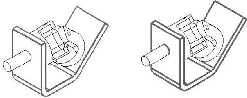
- Open the Component Line Font dialog box for the Bracket part again. This time, set the Line thickness to 0.0787, and click OK. You may have to rebuild the drawing to show the change (Ctrl+B or Ctrl+Q). Figure 18.9 shows a detail of the corners that are created by the thick lines. Notice the notches created at the corners.
FIGURE 18.9 Applying thick edges
- These notches are supposed to be fixed using the End Cap setting at Tools
 Options Document Properties Line Font. Set the End Cap Style to Square. Click OK to exit the Document Properties. In the drawing, select inside the view where you are working and make sure that it is set to High Quality. (The setting is found in the PropertyManager for the view in the Display Style panel. If it is already set to High Quality, then there will be no other view option; if it is not, then there will be an option that is set to Draft Quality.)
The image to the left in Figure 18.8 is the old setting with the draft-quality view, and the image to the right is the new setting with the high-quality view.
- In the Component Line Font dialog box, set the Line Weight setting back to Default for the Bracket part, but keep it on the Bracket layer.
- In the isometric view, Ctrl+click all the tangent edges on the Bracket part, as shown in Figure 18.10. Click the Hide/Show Edges toolbar button on the Line Format toolbar.
- Click the Hide/Show Edges toolbar button. The PropertyManager message changes to indicate that you can now select hidden edges, and the hidden edges are shown. Ctrl+select the hidden edges and right-click when you are done.

Summary
While SolidWorks is not primarily built around the strength of its 2D drawing functionality, it offers more capabilities than most users take advantage of. Layers, colors, and line styles can make your drawings clearer and easier to read.