
These scenarios show how the data integration business patterns described in Chapter 1 can be implemented. These business patterns are as follows:
- Federation: The federation pattern allows access to different data sources, and gives the impression to the requesting application that these are a single logical data source.
- Population: The population pattern gathers data from one or more data sources, processes the data in an appropriate way, and applies it to a target database.
- Synchronization: The synchronization pattern enables bidirectional update flows of data in multi-copy database environments.
A modern SOA-based approach can be taken in order to implement the federation business pattern. A combination of splitter and aggregator building blocks from the mediation layer are used to access data from different sources and to bring the data together to form a view. The necessary building blocks are made available by an ESB component. The following diagram shows the SOA-based implementation of the federation business pattern.

Trigger:
- The application sends a web service request through an SOAP.
- The request causes processing to start on the ESB.
- The ESB splits the request into the number of source systems that are to be used.
- A request takes place for each source system; in this case, using a database adapter, once for Oracle and once for SQL server.
- The results of the two requests are combined by the ESB using an aggregator building block to form a single result view, and this result is then returned to the calling application.
Alternative flow:
- The accesses to the source systems can be run in parallel by the ESB in order to keep the overall response time to a minimum (from the perspective of the calling application)
Modern mashup techniques from Web 2.0 can be regarded as another way of implementing the federation business pattern.
Mashup refers to the creation of new content by seamlessly (re)combining existing content such as text, data, images, audio, or video, to produce a type of collage. Mashups often make use of application programming interfaces (APIs) made available by other web applications.
The following diagram shows the scenario of implementing the federation pattern using the mashup process:

Trigger:
- An application sends a request in a RESTful style.
Primary flow:
- The request is received by the mashup server and a processing pipeline is started.
- The first data source is an Oracle table, which makes information available as a feed through a SQL connection.
- The second source involves a direct connection to an RSS feed using the ATOM protocol, which also returns a feed.
- The two feeds are combined into one single feed, by using a transform operation (in an aggregator building block).
- The result is returned to the requesting application using a publish operation.
The scenario in the following diagram is the traditional implementation of the population business pattern. This involves using a component that supports ETL functionality and is started at a specific time using a job scheduler building block.
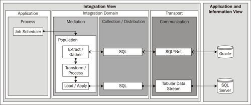
Trigger:
- The job scheduler building block initiates processing at a given time, determined by the job configuration.
Primary flow:
- The start event launches the procedure.
- The extract/gather building block reads the required data from the source, which in this case is an Oracle database.
- The transform/process building block transforms and processes the data.
- The load/apply building block writes the data to the target database, which in this case is a SQL Server database.
The population pattern can also be used effectively in a modern SOA-based environment. In this case, the component with the ETL functionality (population) is encapsulated as a web service and incorporated into an SOA. This enables the population pattern to be used by an integration process, as shown in the following diagram:

- The application sends a web service request using SOAP.
Primary flow:
- The SOAP request initiates a new instance of the integration process.
- To enable the integration process to make use of updated data at a later time, it starts the population procedure via the web service interface, in other words, using an SOAP request, and interrupts/pauses the process.
- The population procedure (ETL processing) is executed and the data is copied from the DB2 database to the Oracle database using the SQL interfaces.
- The integration process is informed that the ETL processing has come to an end by means of an SOAP (callback) request. The process waits for the message with the corresponding receive activity.
- The process restarts and reads the data from the updated source using a database adapter.
In the third variant, the population pattern is also used with an SOA-based approach. However, the population procedure is not triggered by a process, but by a change event from the database.
The Change Data Capture (CDC) method is applied to the source database. CDC has a number of ways of recognizing changes in a source table, for example using database triggers, time stamps or version numbers, or by scanning the database log. Every change identified is published as a CDC event, which a given system can react on. The following image shows the scenario of the event being processed by an ESB, which triggers the population procedure.

Trigger:
- A change event from CDC indicates a change in the data (in Oracle database A).
Primary flow:
- The event is published and forwarded through Oracle Advanced Queuing (AQ), a message infrastructure in the Oracle database.
- An event-driven consumer in the ESB extracts the message (event) from the database queue using an AQ adapter.
- If necessary, the ESB transforms the data from a specific format to a canonical format and forwards the event to the required receiver (message dispatcher). In this case, the CDC event causes the population pattern or the ETL processing to start.
- The population procedure writes the modified data from the source database (Oracle A), to the target database (Oracle B), and transforms the information. As a result, the information is immediately updated in the target database.
- At any time, the application can access the current data in the target database via a web service query from the ESB mediation layer. The ESB uses a database adapter for the SQL access.
Alternative flows:
- The ESB can also forward the event to potential interested receivers by means of a message router (message dispatcher or publish/subscribe).
- The population procedure is not required to carry out a full update of the target database. If the Change Data Capture event contains the primary key, the population procedure can also only be implemented for the relevant records.
This variant applies a modern SOA-based approach using an ESB component, and the Change Data Capture event from the database as triggers. This is shown in the following diagram:

Trigger:
- A record is added or modified in the source Oracle database.
- The modification in the database is identified by the database adapter using a specific strategy, such as polling a timestamp column (in principle, a variant of Change Data Capture).
- An event-driven consumer building block in the ESB reacts to the new or modified record in the source database.
- The information from the modified record is read and published on the bus as a message in a channel.
- A message translator building block can be used to convert the message, if required.
- A database adapter writes the message to the target database (SQL Server).
This implementation of the synchronization pattern makes use of the SOA-based implementation of the population pattern. It duplicates this implementation and applies it in both directions. In other words, two parallel, separate message flows are used on the ESB, and both are implemented as a population pattern, as shown in the following diagram.
The important factor in this scenario is to avoid endless loops. This is because the synchronization in one direction represents an update to the target system, which means that the Change Data Capture procedure must be able to process it. One variant of this pattern involves only certain areas of the source data, which do not overlap in the two source databases (for example, at a client level or a regional level) being modified. Another variant labels updates resulting from the synchronization with a flag or a timestamp in every record, so that the Change Data Capture mechanism can distinguish such updates from "normal" application updates.
In addition, this scenario can lead to conflicts if the same record is modified at the same time in both databases. A cleaning process must be put in place when updates to identical records are possible.

Trigger:
- A record is added or modified in the Oracle or SQL Server database.
Primary flow:
- One database adapter is used for each database to identify modified or new records by means of a polling procedure. If a change is identified, and if it has been made by a user and not by the synchronization process, then the record is sent as a message in a channel on the bus.
- The ESB can carry out an optional transformation, and thus writes the record to the target database through a database adapter.
Alternative flow:
- In order to avoid conflicts, the two message flows on the ESB can communicate with one another.