
HOUR 14
Connecting to the Internet: Initial Operations
What You’ll Learn in This Hour:
• How and why the Internet was created
• ISPs and IXPs
• How traffic is sent across networks using peering arrangements
• The BGP
• More details on IP
• Operations of the TCP and the UDP
In this hour, we look at the Internet in more detail. Using the general concepts outlined in previous hours, we examine how traffic is transported across the Internet through Internet service providers (ISPs) and Internet Exchange Points (IXPs). We examine ideas on how to select an ISP and how we might exploit the features of the Internet Protocol (IP), the Transmission Control Protocol (TCP), and the User Datagram Protocol (UDP) to provide better performance.
Origins of the Internet
In the late 1960s and early 1970s, networks were not designed to allow resource sharing among users in different locations. Network administrators were also reluctant to allow users to tap into their systems due to concerns about security as well as excessive use of their network resources. As a result, it was difficult for a user to share software or data with someone else or, for that matter, to exchange electronic messages. Most existing networks, which unto themselves were few and far between, were “closed.” They were not compatible with others.
During this time, a small group of bright men came up with the common-sense notion to share resources among user applications. (This idea is believed to have been espoused in 1962 by J.C.R. Licklider of MIT.) But to do so, it was recognized network administrators would have to agree on a set of common technologies and standards to allow the networks to communicate with each other. It also followed that applications, such as electronic mail and file transfer, should be standardized to permit interworking end user applications (not just the networks).
Licklider was in charge of computer research at a U.S. Department of Defense establishment named ARPA (the Advanced Research Projects Agency). He and others at ARPA began to think about the usefulness of “computer networks.” Around this time, research was being conducted on packet switching (see Hour 2, “The Benefits of Networking”) to get around the problems of using conventional telephone circuit switches. These packet switches were eventually called Interface Message Processors (IMPs).
By the late 1960s, ARPA and some organizations in the UK had well-conceived visions of packet-switched computer networks. In 1968, a specification (and request for comments) was published for just such a network. It was to be called ARPAnet. By the end of 1969, the ARPAnet was up and running, connecting four sites in California and Utah. With only four sites, it was a modest undertaking, but it was monumental at the time; and it had monumental import for the future.
Thereafter, ARPAnet grew rapidly. In 1972, email was created as an application to run on the network. At about this time, TCP/IP came into existence and was adopted by the Department of Defense in 1980 as the way to do networking. Coupled with DOD’s clout, the decision to use UNIX with these (noncopyrighted) ARPAnet protocols, TCP/IP did indeed become the way to do networking.
During the next three decades, the Internet evolved from the original ARPAnet. It changed from a government network to the public network in existence today. For these next two hours, we will fill in some gaps about the history of the Internet as it relates to our task of learning about computer networks. If you want to know the details of the Internet’s history, go to www.isoc.org/internet/history/brief.shtml.
![]()
In previous hours, we introduced subjects dealing with how to connect to the Internet. For this hour, we delve into more of the details. For review, the list that follows summarizes previous material. It doesn’t contain all the subjects covered earlier, but the most important perquisites for obtaining an Internet connection. If you’re hazy about their functions, it’s a good idea to return to the appropriate hour and review them:
• IP and MAC addresses—Hour 3, “Getting Data from Here to There: How Networking Works”
• Routers, hubs, bridges, and switches—Hour 5, “Network Concepts”
• Routing and forwarding—Hour 5
• Physical media—Hour 5
• DSL and “T1”—Hour 6, “Extending LANs with Wide Area Networks (WANs)”
• Modems—Hour 8, “Remote Networking”
ISPs
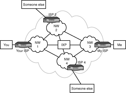
Now that we have a handle on those subjects, let’s focus on how an email message is transported from, say, your computer to mine. Figure 14.1 is used for this discussion. First, we assume that both of us are connected via DSL, dial-up, cable, or some other link to an ISP. Let’s assume that yours is Verizon and mine is AOL. As depicted in Figure 14.1, Verizon is identified as network 1 (NW 1), and AOL is identified as network 3 (NW 3).
FIGURE 14.1 ISPs and IXPs
Second, these companies offer access to the Internet and numerous other services, such as
• Firewalls for security and privacy services
• Assignment of IP addresses
• Assignment of domain names (not yet explained; see Hour 15, “Connecting to the Internet: Key Supporting Operations”)
• Email service
• Spam filters
• Help desk
• Text messaging
• An array of websites for shopping, news, weather, and so on
• Connections to other networks for end-to-end delivery
With the exception of the last item, it’s likely you’re familiar with these services. Notwithstanding, if this last service isn’t provided, the others are worthless. Consequently, the next part of this hour explains how ISPs connect with each other to provide customers with end-to-end service.
IXPs
ISPs frequently connect to IXPs to transfer traffic. In so doing, two networks, such as Verizon and AOL, can connect with each other, without going through so-called third-party networks, such as NW 2 and NW 4 in Figure 14.1. Typically, this more-direct connection reduces costs and the delay of moving traffic end to end. As of this writing, there are roughly 230 IXPs throughout the world.
Another advantage of using an IXP pertains to speed (throughput in bits per second [bps]). In some parts of the world, the physical communications infrastructure (the long-distance link) is poor and expensive to use. The ISPs in these places might only have low-speed, poor-quality links to the Internet. If they can obtain a direct connection to a nearby IXP, they avail themselves of better technology.
The costs of operating an IXP are typically charged back to its participating networks. The fees are based on a combination of port speeds and traffic volume. Some IXPs charge a setup fee and a monthly or annual fee.
For ISPs to use each other’s facilities to transport traffic back and forth between you and me, they first enter into an agreement about this matter. This agreement becomes a peering relationship and entails the discovery and announcement of routes (IP addresses). These advertisements can also contain IP addresses of other ISPs that can be reached by the network that is doing the advertising. (A simplified view of address advertising is provided in Hour 5 [Figure 5.1]). Upon receiving this information, the peer party executes a route filtering operation: It accepts or ignores routes, perhaps deciding to use other routes to reach the IP addresses.
Thus far in this analysis, traffic between NW 1 and NW 3 has been passing through the IXP. In many situations, ISPs forward their traffic between ISPs and not IXPs. A network provider might declare the route between, say, NW 1 and NW 4 to be the primary route. After all, it makes no sense to relay traffic through an IXP if the two ISPs have direct connections. In many situations, the IXP acts as a backup route for directly connected ISPs.
The IXP contains at least one router. Bigger IXPs contain many, usually connected through Gigabit Ethernet at one site. Some IXPs have multiple sites, spread across a geographical region and interconnected with high-speed SONET links.
All ISPs and IXPs use an Internet route discovery protocol to establish associations with other ISPs and IXPs, to advertise IP addresses, and to perform route filtering. This protocol is called the Border Gateway Protocol (BGP).
BGP
BGP establishes and maintains routes between networks in the Internet. For administrative and management purposes, these networks are collectively called and identified by an autonomous system (AS) number. BGP is different from other (older) Internet routing protocols in that it does not make routing decisions (and build routing tables) only on the most efficient route. Equally important, it selects routes between networks based on peering agreements. Thus, BGP allows each network administrator to define a “policy” that directs BPG how to set up logical associations between ASs and advertise IP addresses (prefixes) to construct the routing tables.
Unless you and your team are employed by a large company with substantial networking capabilities, it’s unlikely you’ll be tasked with configuring BGP. Be thankful! It’s a powerful routing protocol, but it has a steep learning curve.
![]()
An example of an IXP is MAE-East. It has sites in Vienna, Virginia; Reston, Virginia; Ashburn, Virginia; New York, New York; and Miami, Florida. It provides several connection services to its members, such as Asynchronous Transfer Mode (ATM) and IP over SONET (Synchronous Optical Network). It connects its five sites with high-speed SONET links.
Peering
Unless you’re a network manager of a large company, you need not know the details of Internet peering. That stated, peering is key to understanding how the thousands of ISPs and IXPs set up their connections so you and I can exchange emails. For the curious reader and for the reader who manages a large set of networks, read on; it’s a fascinating subject whose “modest” goal is moving user data—error-free—around the earth (through multiple networks) in less than one second.
Peering is an association and connection between different Internet networks for the sole purpose of exchanging user traffic. The term has usually been associated with the idea that there are no fees for peering; the networks provide free pass-through service to each other. However, some literature and implementations use the term to connote some kind of settlement (exchange of money) for the arrangement. To clear up this confusion, the term “settlement-free peering” is used to describe nonmonetary arrangements.
Regardless of how peering is defined, the arrangement boils down to one of two scenarios: (a) A network pays another network for access (which is called a settlement); or (b) networks exchange traffic without settlement.
If an IXP is involved in the peering of two networks, the process is called public peering. If the networks arrange for their own interconnections (such as private, leased SONET links), the process is called private peering. Most of the large U.S. networks in the Internet use private peering. Smaller networks opt for public peering.
Peering is a great concept, and its use has been a key factor in the Internet having near-instant global connectivity for any user. It also provides the means to load-level traffic across multiple networks and reduce dependence on only one transit ISP or IXP.
However, human nature and the nature of business might lead a network to decide to resort to depeering—that is, terminating the association and related connection to another network. Reasons for depeering vary. Here are some examples:
• One network is “hogging” the bandwidth of another network and not paying (enough) for it.
• One network isn’t as reliable as the other network.
• One network isn’t as secure as the other network.
• One network has become a direct competitor with the other network for customers.
Notwithstanding these potential problems, Internet peering has evolved to fulfill the surfer’s dream: excluding security and privacy considerations, near-instant access to any Internet-connected computer on earth.
Considerations for Choosing an ISP
Choosing an ISP that meets your needs requires doing some homework, especially if your company’s livelihood depends on the reliable and efficient interworking with the Internet. Here are some ideas to keep in mind during your analysis:
• Is the ISP redundantly connected to upstream links? Redundant connections assure your company of more consistent connections. In case of a failed path to a destination, a redundant link allows a router to reroute traffic.
• Does your ISP have public or private peering relationships? Can it provide you with statistics on throughput, reliability, and delay for all the peering relationships that will affect your company’s traffic?
• Who will supply the equipment for the ISP connection to your network? You need to find out whether the ISP provides and configures necessary equipment, such as routers, as part of the connection cost or whether you will have to purchase and maintain your own connectivity devices.
• Can the ISP provide you with a pool of IP addresses for your network and obtain your domain name for you? Having your own pool of IP addresses provides you with flexibility in bringing new clients onto the network and configuring web servers or DNS servers that require fixed IP addresses. Having a pool of IP addresses is certainly not a requirement to connect to the Internet because there are alternatives, such as Network Address Translation (NAT).
• How will the ISP help you secure your IP network? What is the ISP willing to do to help protect your LAN from both frivolous and malicious attacks over the Internet connection? Find out whether the ISP offers firewalls and NAT.
• What kind and quality of technical support does the ISP offer? Find out whether the ISP offers 24/7 availability for this support.
How and Why TCP/IP Was Created
Throughout this book, frequent references have been made to TCP and IP. We now examine them and discover why they are widely used and how you can use them in your network. To begin our analysis, Figure 14.2 depicts the layered protocol model in relation to TCP/IP.
FIGURE 14.2 TCP/IP and the IP stack

TCP operates in Layer 4 and IP operates in Layer 3 of the Internet/OSI model. This arrangement has significant and positive consequences for transporting traffic across computer networks. To understand why, let’s again look back in time. In December 1970, the Network Control Protocol (NCP) was implemented to transport data in the ARPAnet. The protocol was narrow in its functions: It had limited addressing capabilities, a lack of robustness, and no end-to-end host (user computer) error control. These deficiencies led to the development of TCP.
TCP was designed with these key ideas in mind:
• The ARPAnet would attempt to deliver packets on a best-effort basis. If a packet did not reach its destination, it was not the responsibility of ARPAnet to resend. It was the responsibility of the sending host.
• The “black boxes” that relayed packets (later called routers) would not be aware of the nature of the data in the packets, nor would the boxes retain information about them. Simplicity was the key word.
• The network and attached networks would not be involved with the internal operations of each other.
• No centralized, global control center would exist. Each network was responsible for itself.
TCP initially supported only end-to-end connections where the following occurred:
1. A logical connection (a handshake) was performed between the two hosts.
2. Data was exchanged in an orderly, sequenced fashion. (Retransmissions occurred in the event of problems.)
3. Another handshake took place to release the logical connection.
Soon after TCP was developed, the designers recognized the flaws of this approach. First, some applications did not need end-to-end acknowledgments and the resending of packets. For example, they knew some traffic would not suffer significant quality problems if an occasional packet was lost. Even more, applications with the need for fast response times could not tolerate the delay of waiting for the retransmitted packet.
The result was the division of TCP into two protocols: TCP and IP. TCP would be responsible for end-to-end flow control, sequencing, and packet recovery. IP would be responsible for addressing and routing of the packet. Therefore, TCP did not have to execute in the routers, only at the hosts. This idea might seem rather insignificant, but it translates into a simple, yet elegant and robust model. Figure 14.3 helps explain why. (As before, the solid arrows symbolize the sending and receiving of traffic down and up the layers; the dashed lines symbolize the logical exchange of traffic between peer layers; and the dashed/dotted lines symbolize the physical transfer of traffic across communications links.)
FIGURE 14.3 Transporting traffic with TCP/IP
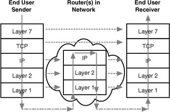
• TCP’s significant overhead of handshaking to set up a logical connection, sequence traffic, and perhaps resend packets does not reside in the network. It resides in the end user machines.
• The network black boxes (again, called routers today) use the destination address in the IP header to make forwarding decisions. These routers are not tasked with examining data in the packet that deals with Layer 4 or Layer 7.
These two factors lead to (a) a highly efficient and simple network that typically relays traffic with low latency (low delays), and (b) a highly robust service, because the users’ computers are executing TCP. The old adage, “Hindsight is 20-20,” is altered to describe the amazing foresight of the Internet pioneers, “Foresight was 20-20.”
Furthermore, for those applications that still wanted some of the features of TCP (sockets, explained shortly) but did not want handshakes, packet resending, and such, another (simple) protocol was created. It’s called UDP and is widely used today for applications such as Voice over IP (VoIP).
Ports
One of the most important functions of TCP and UDP pertains to the Internet port numbers that are placed in fields of their headers; one field for a source port number; another field for a destination port number. As depicted in Figure 14.2, the sending and receiving hosts (computers) use these port numbers to identify the specific type of Layer 7 traffic that resides in the packet. For example, if the data is a BGP message, the port number for passing this data to the BGP software is 179. As another example, if the data pertains to email’s POP3, the port number is 110.
Port numbers are managed by the Internet Assigned Numbers Authority (IANA) and are allocated by dividing them into these ranges:
• Well-known ports: Range of 0–1023—Typically set aside for widely used L_7 applications, but these types of applications might have a port number in the registered port range.
• Registered ports: Range of 1024–49151—Specific assignments to less widely used applications or vendor-specific applications. For example, port 1270 identifies Microsoft Systems Center Operations Manager. However, this range also includes widely used Internet protocols; for example, port 1293 is reserved for the Internet Security Protocol (IPSec).
• Dynamic or private ports: Range of 49152–65535—No ports can be registered in this range.
As a general rule, the assigned ports identify a server port and the server software. The client port is selected by the client software (the client’s operating system) for each connection by simply starting at number 1024 and wrapping at number 4096. You might ask: Does the client’s use of so-called registered numbers create confusion? The answer is no. The operating system keeps track of the source port numbers it chooses and assigns a special ID number to each one.
Table 14.1 lists some of TCP/UDP ports and their assigned numbers.
TABLE 14.1 Examples of TCP/UDP Ports

Sockets
A port makes up part of a socket, which is the complete identifier for the end-to-end connection between two hosts. Thus far, we’ve been using the term “application” to designate the software that’s identified by ports (and now sockets). You might also come across the terms “process” or “thread,” depending on the literature or operating system involved. Whatever the term used, an Internet socket is (a) the interface between the L_7 process and TCP or UDP, and (b) the end-to-end connection between two hosts.
The complete bidirectional connection is identified by a socket pair: a send socket and a receive socket. Each socket consists of (1) an IP address, (2) a port number, and (3) the “protocol” field in the IP header that indentifies if the packet contains a TCP or UDP header (and perhaps others, which are not pertinent to our discussion).
Therefore, for an Internet session to take place, the two communicating parties are uniquely identified (throughout the entire Internet) by the following:
• Send socket—(1) Source IP address, (2) Source socket, (3) Protocol ID
• Receive socket—(1) Destination IP address, (2) Destination port, (3) Protocol ID
One of the main functions of a TCP handshake is to set up the connection so it is thereafter identified by the socket pair. The appropriate L_7 application can then process the incoming packet by the use of the receive socket identifier.
In a client/server network, the operating systems might set a TCP server socket to be in a listening state, which means it’s waiting for clients to send in a TCP handshake packet. If a remote client has not yet sent a connection request, this listening socket simply sets the remote IP address to 0.0.0.0 and the remote port number to 0. The operating system is responsible for keeping track of all Internet sessions by storing information about each socket pair.
You and your team might have to become familiar with socket operations. They vary, depending on the operating system. But they’re all consistent with regard to the rules documented in the TCP standards. You might want to use the UNIX netsat-an command, which will provide you a list of all sockets that the OS currently defines; as well as netstat-b, which will provide information on which application program created which socket. If you do use these commands, you won’t see the state of a UDP socket, because UDP is a connectionless protocol.
IP Features
Hour 3 explained the major features of IP. This section provides more details. Don’t forget that specific IP implementations might not perform these services:
• Type of Service (TOS)—Requests various levels of (a) precedence, (b) delay, (c) throughput, and (d) reliability of packet delivery. Some implementations use the precedence and reliability fields to identify packets for network control operations, such as a packet containing route advertisements. For your private internets, consider using the delay and throughput fields to establish enhanced quality of service support for time-sensitive traffic, such as voice and video.
• Time to Live (TTL)—Time the packet can remain active as it finds its way to the destination. Often implemented with a maximum permissible hop count (number of nodes that can be traversed). This option ensures that IP packets don’t “thrash around” in the network indefinitely—a problem called endless loops. If you become concerned that significant volumes of your traffic are not arriving at the proper destinations, consider checking how this field has been set. It could be that the hop count value is too low.
• Protocol—Identifies the next protocol that’s to receive the packet at the destination. Protocol 6 is reserved for TCP; protocol 17 is reserved for UDP. For private networks, some companies use their own protocol numbers to pass IP packets to tailored Layer 4 processes.
• Fragmentation—Allows an IP packet larger than the permitted L_2 frame size to be reduced to fit into the frame and then reassembled at the receiving IP node.
• Options—Provides for other optional services but isn’t used much in current networks. Here are two examples of IP options: (1) route recording: stores the IP address of each node that processes the packet; (2) source routing: contains IP addresses of the nodes that participate in an end-to-end route. These useful services have now been “taken over” by other protocols, such as TraceRoute and ATM.
TCP Features
Like IP, TCP offers a range of services to the user. Like IP, the services vary, depending on the software vendor’s product. Also like IP, the services might be transparent to the user, as well as nonconfigurable. Here is a summary of TCP services:
• Connection services—TCP is a connection-oriented protocol that maintains status and state information about each socket pair. This ongoing connection awareness, and its associated connection setup and closing, provides a network administrator with a lot of information about user sessions.
• Reliable data transfer—Ensures all data arrives error free at the receiving TCP module. Using an error-check field in the header, the receiving TCP module will discard damaged packets. The sending TCP will not receive proper acknowledgments from the receiver and will resend lost or damaged data. If data arrives correctly, the sending module will receive an acknowledgment packet from the receiver. This end-to-end integrity operation is quite important to users.
• Proper sequencing—TCP ensures all user packets are assembled in the proper sequential order at the receiving host. This operation allows network components (say, IP at L_3, ATM at L_2, or SONET at L_1) to mix up a user’s original payload (for example, sending packets through different routers in the Internet). TCP will not present a packet across the receiving socket until all packets have arrived in order.
• Flow control—TCP can flow-control the sending socket, which can be a useful tool to prevent buffer overrun and saturation of the receiving machine.
• Graceful close—Before the socket pair and the associated end-to-end connection are closed, TCP makes certain all packets associated with this connection have been received at the destination host.
UDP Features
Many applications do not require the connection-oriented and data integrity features of TCP. Indeed, not only do they not need them, but they can’t tolerate them. Because of its behavior, TCP introduces delay (latency) in ongoing packet delivery between two parties. As an alternative, UDP is widely employed for the following scenarios:
• Voice or video applications—This traffic cannot tolerate the delay in waiting for the arrival of a retransmitted packet. Fortunately, a few missing packets in a voice conversation or a video show cannot be detected by the receiving audience. UDP is ideal for these applications.
• The L_7 module performs TCP services—If a Layer 7 application is programmed to perform retransmission, resequencing, flow control, and other TCP-like services, it makes no sense to duplicate them.
Summary
“TCP/IP.” The term is so common we hear it spoken in movies. We see it written in mass-market books.
We watch examples of Internet socket management on TV. Jack Bauer and his 24 companions are constantly opening “sockets” to thwart the bad guys: “Let me open a socket, Jack. That’s all I need to tap into 10 FBI databases, 20 GPS connections, 30 AT&T mobile phone calls, and 40 CIA terrorist-simulation models to solve this problem!”
In today’s society, fiction is often stranger than facts. But for this hour, we’ve stuck with facts and learned about the basic tools for connecting into the Internet. In so doing, we also learned how the Internet architecture and protocols came into existence. We now know how our data “moves” from ISPs and IXPs to our remote email partner. We leaned a bit more about IP and a lot more about ports, sockets, TCP, and UDP.
In the next hour, we stay with the subject of “connecting to the Internet” and examine several other important protocols to achieve this connectivity and to provide yet more (and essential) services.
Q&A
Q. Fill in likely implementations for an Internet LAN link:
L_1: _______________
L_2: _______________
L_3: _______________
L_4: _______________
A. L_1: Ethernet
L_2: Ethernet
L_3: IP
L_4: TCP or UDP
Q. Fill in likely implementations for an Internet UNI link:
L_1: _______________
L_2: _______________
L_3: _______________
L_4: _______________
A. L_1: DSL, cable modem, T-carrier family, or satellite
L_2: ATM or MPLS
L_3: IP
L_4: TCP or UDP
Q. What is peering?
A. Peering is an agreement between ISPs to use each other’s facilities to transport traffic back and forth between their respective customers through each other’s networks.
Q. What is the purpose of the Border Gateway Protocol (BGP)?
A. BGP sets up routes and peering arrangements between networks.
A. It’s a unique number assigned to an application process, which usually operates in L_7 of the OSI model.
Q. What is the difference between a port and a socket?
A. A port number is one part of a socket. A socket consists of a port number, an IP address, and a protocol ID.
Q. Does the Internet provide for end-to-end data integrity? Why or why not?
A. The Internet doe not provide end-to-end integrity. That task rests with TCP, which operates in the users’ machines (host computers). If the Internet provided end-to-end data integrity, significant delay and overhead would result. Besides, some user applications do not need or want end-to-end data integrity services.
Q. What are the differences between TCP and UDP?
A. TCP is a rich protocol providing connection management, socket services (with the OS), flow control, resequencing, and end-to-end integrity. UDP is a bare-bones protocol that provides socket services (with the OS).