
Chapter 22
Intersection Test Methods
“I’ll sit and see if that small sailing cloud Will hit or miss the moon.”
—Robert Frost
Intersection testing is often used in computer graphics. We may wish to determine whether two objects collide, or to find the distance to the ground so we can keep the camera at a constant height. Another important use is finding whether an object should be sent down the pipeline at all. All these operations can be performed with intersection tests. In this chapter, we cover the most common ray/object and object/object intersection tests.
In collision detection algorithms, which are also built upon hierarchies, the system must decide whether or not two primitive objects collide. These objects include triangles, spheres, axis-aligned bounding boxes (AABBs), oriented bounding boxes (OBBs), and discrete oriented polytopes (k-DOPs).
As we have seen in Section 19.4, view frustum culling is a means for efficiently discarding geometry that is outside the view frustum. Tests that decide whether a bounding volume (BV) is fully outside, fully inside, or partially inside a frustum are needed to use this method.
In all these cases we have encountered a certain class of problems that require intersection tests. An intersection test determines whether two objects, A and B, intersect, which may mean that A is fully inside B (or vice versa), that the boundaries of A and B intersect, or that they are disjoint. However, sometimes more information may be needed, such as the closest intersection point to some location, or the amount and direction of penetration.
In this chapter we focus on fast intersection test methods. We not only present the basic algorithms, but also give advice on how to construct new and efficient intersection test methods. Naturally, the methods presented in this chapter are also of use in offline computer graphics applications. For example, the ray intersection algorithms presented in Sections 22.6 through 22.9 are used in ray tracing programs.
After briefly covering hardware-accelerated picking methods, this chapter continues with some useful definitions, followed by algorithms for forming bounding volumes around primitives. Rules of thumb for constructing efficient intersection test methods are presented next. Finally, the bulk of the chapter consists of a cookbook of intersection test methods.
22.1 GPU-Accelerated Picking
It is often desirable to let the user select a certain object by picking (clicking) on it with the mouse or any other input device. Naturally, the performance of such an operation needs to be high.
If you need all the objects at a point or larger area on the screen, regardless of visibility, a CPU-side picking solution may be warranted. This type of picking is sometimes seen in modeling or CAD software packages. It can be solved efficiently on the CPU by using a bounding volume hierarchy (Section ). A ray is formed at the pixel’s location, passing from the near to the far plane of the view frustum. This ray is then tested for intersection with the bounding volume hierarchy as needed, similar to what is done to accelerate tracing rays in global illumination algorithms. For a rectangular area formed by the user defining a rectangle on the screen, we would create a frustum instead of a ray and test it against the hierarchy.
Intersection testing on the CPU has several drawbacks, depending on the requirements. Meshes with thousands of triangles can become expensive to test triangle by triangle unless some acceleration structure such as a hierarchy or grid is imposed on the mesh itself. If accuracy is important, geometry generated by displacement mapping or GPU tessellation needs to be matched by the CPU. For alpha-mapped objects such as tree foliage, the user should not be able to select fully transparent texels. A considerable amount of work on the CPU is needed to emulate texture access, along with any other shaders that discard texels for any reason.
Often we need only what is visible at a pixel or in an area of the screen. For this type of selection, use the GPU pipeline itself. One method was first presented by Hanrahan and Haeberli [661]. To support picking, the scene is rendered with each triangle, polygon, or mesh object having a unique identifier value, which can be thought of as a color. This idea is similar in intent to the visibility buffer, forming an image similar to that in Figure on page 906. The image formed is stored offscreen and is then used for extremely rapid picking. When the user clicks on a pixel, the color identifier is looked up in this image and the object is immediately identified. These identifier values can be rendered to a separate render target while performing standard rendering using simple shaders, so the cost is relatively low. The main expense may be that from reading pixels back from the GPU to CPU.
Any other type of information that the pixel shader receives or computes can also be stored in an offscreen target. For example, the normal or texture coordinates are obvious candidates. It is also possible to find the relative location of a point inside a triangle using such a system [971] by taking advantage of interpolation. In a separate render target each triangle is rendered with the colors of the triangle vertices as red (255, 0, 0), green (0, 255, 0), and blue (0, 0, 255). Say that the interpolated color of the selected pixel is (23, 192, 40), This means that the red vertex contributes with a factor 23 / 255, the green with 192 / 255, and the red with 40 / 255. The values are barycentric coordinates, which are discussed further in Section 22.8.1.
Picking using the GPU was originally presented as part of a three-dimensional paint system. Such picking is particularly well adapted for such systems, where the camera and the objects are not moving, as the entire picking buffer can be generated once and reused. For picking when the camera is moving, another approach is to render the scene again to a tiny target, e.g., , using an off-axis camera focusing on a minute part of the screen. CPU-side frustum culling should eliminate almost all geometry and only a few pixels are shaded, making this pass relatively quick. For picking all objects (not just visible ones), this tiny window method could be performed several times, using depth peeling or simply not rendering previously selected objects [298].
22.2 Definitions and Tools
This section introduces notation and definitions useful for this entire chapter.
A ray, , is defined by an origin point, , and a direction vector, (which, for convenience, is usually normalized, so ). Its mathematical formula is shown in Equation 22.1, and an illustration of a ray is shown in Figure 22.1:
(22.1)
The scalar t is a variable that is used to generate different points on the ray, where t-values of less than zero are said to lie behind the ray origin (and so are not part of the ray), and the positive t-values lie in front of it. Also, since the ray direction is normalized, a t-value generates a point on the ray that is situated t distance units from the ray origin.

Figure 22.1. A simple ray and its parameters: (the ray origin), (the ray direction), and t, which generates different points on the ray, .
In practice, we often also store a current distance l, which is the maximum distance we want to search along the ray. For example, while picking, we usually want the closest intersection along the ray; objects beyond this intersection can safely be ignored. The distance l starts at . As objects are successfully intersected, l is updated with the intersection distance. Once l is set, the ray becomes a line segment for testing. In the ray/object intersection tests we will be discussing, we will normally not include l in the discussion. If you wish to use l, all you have to do is perform the ordinary ray/object test, then check l against the intersection distance computed and take the appropriate action.
When talking about surfaces, we distinguish implicit surfaces from explicit surfaces. An implicit surface is defined by Equation 22.2:
(22.2)
Here, is any point on the surface. This means that if you have a point that lies on the surface and you plug this point into f, then the result will be 0. Otherwise, the result from f will be nonzero. An example of an implicit surface is , which describes a sphere located at the origin with radius r. It is easy to see that this can be rewritten as , which means that it is indeed implicit. Implicit surfaces are briefly covered in Section 17.3, while modeling and rendering with a wide variety of implicit surface types is well covered in Gomes et al. [558] and de Araújo et al. [67].
An explicit surface, on the other hand, is defined by a vector function and some parameters , rather than a point on the surface.
These parameters yield points, , on the surface. Equation 22.3 below shows the general idea:
(22.3)
An example of an explicit surface is again the sphere, this time expressed in spherical coordinates, where is the latitude and longitude, as shown in Equation 22.4:
(22.4)
As another example, a triangle, , can be described in explicit form like this: , where , and must hold.
Finally, we shall give definitions of some common bounding volumes other than the sphere.
Definition An axis-aligned bounding box (also called a rectangular box), AABB for short, is a box whose faces have normals that coincide with the standard basis axes. For example, an AABB A is described by two diagonally opposite points, and , where , .
Figure 22.2 contains an illustration of a three-dimensional AABB together with notation.

Figure 22.2. A three-dimensional AABB, A, with its extreme points, and , and the axes of the standard basis.
Definition An oriented bounding box, OBB for short, is a box whose faces have normals that are all pairwise orthogonal—i.e., it is an AABB that is arbitrarily rotated. An OBB, B, can be described by the center point of the box, , and three normalized vectors, , , and , that describe the side directions of the box. Their respective positive half-lengths are denoted , , and , which is the distance from to the center of the respective face.
A three-dimensional OBB and its notation are depicted in Figure 22.3.

Figure 22.3. A three-dimensional OBB, B, with its center point, , and its normalized, positively oriented side vectors, , , and . The half-lengths of the sides, , , and , are the distances from the center of the box to the center of the faces, as shown.

Figure 22.4. An example of a two-dimensional 8-DOP for a tea cup, with all normals, , shown along with the first slab, , and the “size” of the slab: and .
Definition A k-DOP (discrete oriented polytope) is defined by k / 2 (where k is even) normalized normals (orientations), , , and with each two associated scalar values and , where . Each triple ( , , ) describes a slab, , which is the volume between the two planes, and , and where the intersection of all slabs, , is the actual k-DOP volume. The k-DOP is defined as the tightest set of slabs that bound the object [435]. AABBs and OBBs can be represented as 6-DOPs, as each has six planes defined by three slabs. Figure 22.4 depicts an 8-DOP in two dimensions.
For the definition of a convex polyhedron, it is useful to use the concept of half-spaces of a plane. The positive half-space includes all points where , and the negative half-space is .
Definition A convex polyhedron is a finite volume defined by the intersection of the negative half-spaces of p planes, where the normal of each plane points away from the polyhedron.
AABBs, OBBs, and k-DOPs, as well as any view frustum, are all particular forms of convex polyhedra. More complex k-DOPs and convex polyhedra are used primarily for collision detection algorithms, where computing precise intersection of the underlying meshes can be costly. The extra planes used to form these bounding volumes can trim additional volume from the object and so justify the additional cost involved.
Two other bounding volumes of interest are line swept spheres and rectangle swept spheres. These are also more commonly called capsules and lozenges, respectively, and examples are shown in Figure 22.5.

Figure 22.5. A line swept sphere and rectangle swept sphere, a.k.a. capsule and lozenge.
A separating axis specifies a line in which two objects that do not overlap (are disjoint) have projections onto that line that also do not overlap. Similarly, where a plane can be inserted between two three-dimensional objects, that plane’s normal defines a separating axis. An important tool for intersection testing [576,592] follows, one that works for convex polyhedra such as AABBs, OBBs, and k-DOPs. It is an aspect of the separating hyperplane theorem [189]. 1
Separating Axis Test (SAT). For any two arbitrary, convex, disjoint polyhedra, A and B, there exists at least one separating axis where the projections of the polyhedra, which form intervals on the axis, are also disjoint. This does not hold if one object is concave. For example, the walls of a well and a bucket inside may not touch, but no plane can divide them. Furthermore, if A and B are disjoint, then they can be separated by an axis that is orthogonal (i.e., by a plane that is parallel) to one of the following [577]:
- A face of A.
- A face of B.
- An edge from each polyhedron (e.g., a cross product).
The first two tests say that if one object is entirely on the far side of any face of the other object, they cannot overlap. With the faces handled by the first two tests, the last test is based on the edges of the objects. To separate the objects with the third test, we want to squeeze in a plane (whose normal is the separating axis) as close to both objects as possible, and such a plane cannot lie any closer to an object than on one of its edges. So, the separating axes to test are each formed by the cross product of an edge from each of the two objects. This test is illustrated for two boxes in Figure 22.6.

Figure 22.6. Separating axis. Call the blue box A and the yellow box B. The first image shows B fully to the right of the right face of A, the second shows A fully below the lower left face of B. In the third no face forms a plane that excludes the other box, so an axis formed from the cross product of the upper right edge of A and lower left of B defines the normal of a plane separating the two objects.
Note that the definition of a convex polyhedron is liberal here. A line segment and a convex polygon such as a triangle are also convex polyhedra (though degenerate, since they enclose no volume). A line segment A does not have a face, so the first test disappears. This test is used in deriving the triangle/box overlap test in Section 22.12 and the OBB/OBB overlap test in Section 22.13.5. Gregorius [597] notes an important optimization for any intersection test using the separating axis: temporal coherence. If a separating axis was found in this frame, store this axis as the first to test for the pair of objects in the next frame.
To return to the discussion of methods that can be brought to bear, a common technique for optimizing intersection tests is to make some simple calculations early on that can determine whether the ray or object misses the other object. Such a test is called a rejection test, and if the test succeeds, the intersection is said to be rejected.
Another approach often used in this chapter is to project the three-dimensional objects onto the “best” orthogonal plane (xy, xz, or yz), and solve the problem in two dimensions instead.
Finally, due to numerical imprecision, we often use a minuscule number in the intersection tests. This number is denoted (epsilon), and its value will vary from test to test. However, often an epsilon is chosen that works for the programmer’s problem cases (what Press et al. [1446] call a “convenient fiction”), as opposed to doing careful roundoff error analysis and epsilon adjustment. Such code used in another setting may well break because of differing conditions. Ericson’s book [435] discusses the area of numerical robustness in depth in the context of geometric computation. This caveat firmly in place, we sometimes do attempt to provide epsilons that are at least reasonable starting values for “normal” data, small scale (say less than 100, more than 0.1) and near the origin.
22.3 Bounding Volume Creation
Given a collection of objects, finding a tight fitting bounding volume is important to minimizing intersection costs. The chance that an arbitrary ray will hit any convex object is proportional to that object’s surface area (Section 22.4). Minimizing this area increases the efficiency of any intersection algorithm, as a rejection is never slower to compute than an intersection. In contrast, it is often better to minimize the volume of each BV for collision detection algorithms. This section briefly covers methods of finding optimal or near-optimal bounding volumes given a collection of polygons.
22.3.1. AABB and k-DOP Creation
The simplest bounding volume to create is an AABB. Take the minimum and maximum extents of the set of polygon vertices along each axis and the AABB is formed. The k-DOP is an extension of the AABB: Project the vertices onto each normal, , of the k-DOP, and the extreme values (min,max) of these projections are stored in and . These two values define the tightest slab for that direction. Together, all such values define a minimal k-DOP.
22.3.2. Sphere Creation
Bounding sphere formation is not as straightforward as determining slab extents. There are a number of algorithms that perform this task, and these have speed versus quality trade-offs. A fast, constant-time single pass algorithm is to form an AABB for the polygon set and then use the center and the diagonal of this box to form the sphere. This sometimes gives a poor fit, which can possibly be improved by another pass: Starting with the center of the AABB as the center of the sphere BV, go through all vertices once again and find the one that is farthest from this center (comparing against the square of the distance, to avoid taking the square root). This is then the new radius. See Figure 22.7.

Figure 22.7. Bounding spheres. At its simplest, on the left, an object can have a bounding sphere around its bounding box. If the object does not extend to any corner of the bounding box, the sphere can be improved by using the box’s center and running through all the vertices to find the most distant for setting the sphere’s radius, as in the middle image. A smaller radius is possible by moving the sphere’s center, as shown on the right.
These two techniques need only slight modification if you are nesting child spheres inside a parent sphere. If all the child spheres have the same radius, the centers can be treated as vertices and this child radius is added to the parent sphere’s radius at the end of either process. If the radii vary, the AABB bounds can be found by including these radii in the bounds calculations to find a reasonable center. If the second pass is performed, add each radius to the distance of the point from the parent’s center.
Ritter [1500] presents a simple algorithm that creates a near-optimal bounding sphere. The idea is to find the vertex that is at the minimum and the vertex at the maximum along each of the x-, y-, and z-axes. For these three pairs of vertices, find the pair with the largest distance between them. Use this pair to form a sphere with its center at the midpoint between them and a radius equal to the distance to them. Go through all the other vertices and check their distance d to the center of the sphere. If the vertex is outside the sphere’s radius r, move the sphere’s center toward the vertex by , set the radius to , and continue. This step has the effect of enclosing the vertex and the existing sphere in a new sphere. After this second time through the list, the bounding sphere is guaranteed to enclose all vertices.
Welzl [1867] presents a more complex algorithm, which is implemented by Eberly [404,1574] and Ericson [435] among others, with code on the web. The idea is to find a supporting set of points defining a sphere. A sphere can be defined by a set of two, three, or four points on its surface. When a vertex is found to be outside the current sphere, its location is added to the supporting set (and possibly old support vertices removed from the set), the new sphere is computed, and the entire list is run through again. This process repeats until the sphere contains all vertices. While more complex than the previous methods, this algorithm guarantees that an optimal bounding sphere is found.
Ohlarik [1315] compares the speed of variants of both Ritter’s and Welzl’s algorithms. A simplified form of Ritter’s can cost only more than the basic version, however it can sometimes give worse results, so running both is worthwhile. Eberly’s implementation of Welzl’s algorithm is expected to be linear for a randomized list of points, but runs slower by an order of magnitude or so.
22.3.3. Convex Polyhedron Creation
One general form of bounding volume is the convex polyhedron. Convex objects can be used with the separating axis test. AABBs, k-DOPs, and OBBs are all convex polyhedra, but tighter bounds can be found. Just as k-DOPs can be thought of as trimming off more volume from an object by adding additional pairs of planes, a convex polyhedron can be defined by an arbitrary set of planes. By trimming off additional volume, more expensive tests involving the whole mesh of the enclosed polygonal object can be avoided. We want to “shrink-wrap” our polygonal object and find this set of planes, which form the Figure 22.8 shows an example. The convex hull can be found with, for example, the Quickhull algorithm [100,596]. Despite the name, the process is slower than linear time, and so generally is performed as an offline preprocess for complex models.

Figure 22.8. The convex hull of a teapot computed using Quickhull [596]. (Image courtesy of Dirk Gregorius, Valve Corporation.)
As can be seen, this process may result in a large number of planes, each defined by a polygon on the convex hull. In practice we may not need this level of precision. First creating a simplified version of the original mesh, possibly expanded outward to fully encompass the original, will yield a less accurate but simpler convex hull. Also note that for k-DOPs, as k increases, the BV increasingly resembles the convex hull.
22.3.4. OBB Creation
An object may have a natural OBB, in that it starts with an AABB and then undergoes a rotation that thus makes the AABB into an OBB. However, the OBB then used may not be optimal. Imagine a flagpole modeled to extend from a building at an angle. An AABB around it is not as tight as an OBB extending along its length. For models without obvious best axes, OBB formation, with its arbitrary basis orientation, is even more involved than finding a reasonable bounding sphere.
A noticeable amount of work has been done on creating algorithms for this problem. An exact solution by O’Rourke [1338] from 1985 runs in time. Gottschalk [577] presents a faster, simpler method that gives an approximation for the best OBB. It first computes the convex hull of the polygonal mesh, to avoid model vertices inside this volume that could bias the results. Principle component analysis (PCA), which runs in linear time, is then used to find reasonable OBB axes. A drawback of this method is that the boxes are sometimes loose-fitting [984]. Eberly describes a method for computing a minimum-volume OBB using a minimization technique. He samples a set of possible directions for the box, and uses the axes whose OBB is smallest as a starting point for the numeric minimizer. Powell’s direction set method [1446] is then used to find the minimum volume box. Eberly has code for this operation on the web [404]. There are yet other algorithms; Chang et al. [254] give a reasonable overview of previous work and present their own minimization technique that uses a genetic algorithm to help search the solution space.
Here we present an algorithm from Larsson and Källberg [984], a near-optimal method that does not need the convex hull and executes in linear time. It usually provides better quality than Gottschalk’s PCA-based method, is considerably faster to execute, lends itself to SIMD parallelization, and has code provided by the authors. First a k-DOP is formed for the object, and a pair (any pair) of vertices touching the opposite sides of each k-DOP slab is saved. All these pairs of vertices together are called the extremal points of the object. So, for example, a 26-DOP generates 13 pairs of points, and some of these points may specify the same vertex, possibly giving a smaller overall set. The “best OBB” is initialized to the AABB surrounding the object. The algorithm then proceeds by finding OBB orientations that are likely to provide a better fit. A large base triangle is constructed, and two tetrahedra are extended from its face. These create a set of seven triangles that yield potentially near-optimal OBBs.
The pair of points that are farthest away from each other form one edge of the base triangle. The vertex from the remaining extremal points that is farthest from this edge’s line forms the third point of the triangle. Each triangle edge and the normal to the edge in the triangle’s plane are used to form two axes for a potential new OBB. The remaining extremal points are projected onto these axes to find the two-dimensional bounds in the plane for each of the three OBBs. See Figure 22.9. The smallest surrounding two-dimensional rectangle is used to choose the best OBB from the three. Since the height, the distance along the triangle’s normal, of any of these three OBBs will be the same, the two-dimensional bounding box around each is sufficient to decide which is the best.

Figure 22.9. Near-optimal OBB formation; keep in mind that all the points are in three dimensions. For each k-DOP’s slab (marked by a pair of colored lines), there is a pair of points at its limits, marked in black; the two vertices at the bottom are each at the extreme for two slab planes. The other vertices, marked in gray, are not used in the following steps. Of the four pairs, the two vertices farthest apart are used to form an edge. The extremal point farthest from this edge’s line is used to form a triangle with the edge. Three boxes are formed, each using a triangle edge to define its axes and the remaining extremal points to define its boundaries. Of these three, the best box is saved.
The remaining extremal points are then used to find the extents of this OBB in three dimensions by projection against the triangle’s normal. This fully formed OBB is checked against the initial AABB to see which is better. The two extremal points found during this process, one at the maximum and one at the minimum height, are then used to form two tetrahedra, with the original large triangle as the base of each. Each tetrahedron in turn forms three additional triangles, and the process of evaluating the triangle’s three candidate OBBs is performed for each as done for the original triangle. The best two-dimensional OBB for each triangle is similarly extended along its height, as before, but only to get the final size of the candidate OBB, not to form yet more triangles. A total of seven triangles is formed, and one full OBB is generated and compared from each.
Once the best OBB is found, all points in the original object are projected onto its axes to increase its size as needed. A final check is made against the original AABB to see if this OBB actually gives a better fit. This whole process is faster than previous techniques and benefits from using a small set of extremal points for most steps. Notably, the authors prefer optimizing the bounding box based on surface area, not volume, for reasons we cover in the next section.
22.4 Geometric Probability
Common geometric operations include whether a plane or ray intersects an object, and whether a point is inside it. A related question is what is the relative probability that a point, ray, or plane intersects an object. The relative probability of a random point in space being inside an object is fairly obvious: It is directly proportional to the volume of the object. So, a box is 6 times as likely to contain a randomly chosen point as is a box.
For an arbitrary ray in space, what is the relative chance of a ray intersecting one object versus another? This question is related to another question: What is the average number of pixels covered by an arbitrarily oriented object when using an orthographic projection? An orthographic projection can be thought of as a set of parallel rays in the view volume, with a ray traveling through each pixel. Given a randomly oriented object, the number of pixels covered is equal to the number of rays intersecting the object.
The answer is surprisingly simple: The average projected area of any convex solid object is one fourth of its surface area. This is clearly true for a sphere on the screen, where its orthographic projection is always a circle with area and its surface area is . This same ratio holds as the average projected for any other arbitrarily oriented convex object, such as a box or k-DOP. See Nienhuys’ article [1278] for an informal proof.
A sphere, box, or other convex object always has a front and a back at each pixel, so the depth complexity is two. The probability measure can be extended to any polygon, as a (two-sided) polygon always has a depth complexity of one. As such, the average projected area of any polygon is one half its surface area.
This metric is referred to as the surface area heuristic (SAH) [71,1096,1828] in the ray tracing literature, and it is important in forming efficient visibility structures for data sets. One use is in comparing bounding volume efficiency. For example, a sphere has a relative probability of 1.57 ( ) of being hit by a ray, compared to an inscribed cube (i.e., a cube with its corners touching the sphere). Similarly, a cube has a relative probability of 1.91 ( ) of being hit, versus a sphere inscribed inside it.
This type of probability measurement can be useful in areas such as level of detail computation. For example, imagine a long and thin object that covers many fewer pixels than a rounder object, yet both have the same bounding sphere size. Knowing the hit ratio in advance from the area of its bounding box, the long and thin object may be considered relatively less important in visual impact.
We now have a point’s probability of enclosure as being related to volume, and a ray’s probability of intersection as being related to surface area. The chance of a plane intersecting a box is directly proportional to the sum of the extents of the box in three dimensions [1580]. This sum is called the object’s mean width. For example, a cube with an edge length of 1 has a mean width of . A box’s mean width is proportional to its chance of being hit by a plane. So, a box has a measure of 3, and a box a measure of 6, meaning that the second box is twice as likely to be intersected by an arbitrary plane.
However, this sum is larger than the true geometric mean width, which is the average projected length of an object along a fixed axis over the set of all possible orientations. There is no easy relationship (such as surface area) among different convex object types for mean width computation. A sphere of diameter d has a geometric mean width of d, since the sphere spans this same length for any orientation. We will leave this topic by simply stating that multiplying the sum of a box’s dimensions (i.e., its mean width) by 0.5 gives its geometric mean width, which can be compared directly to a sphere’s diameter. So, the box with measure 3 has a geometric mean width of . A sphere bounding this box has a diameter of . Therefore a sphere surrounding a cube is times as likely to be intersected by an arbitrary plane.
These relationships are useful for determining the benefits of various algorithms. Frustum culling is a prime candidate, as it involves intersecting planes with bounding volumes. Another use is for determining whether and where to best split a BSP node containing objects, so that frustum culling performance becomes better (Section 19.1.2).
22.5 Rules of Thumb
Before we begin studying the specific intersection methods, here are some rules of thumb that can lead to faster, more robust, and more exact intersection tests. These should be kept in mind when designing, inventing, and implementing an intersection routine:
- Perform computations and comparisons early on that might trivially reject or accept various types of intersections to obtain an early escape from further computations.
- If possible, exploit the results from previous tests.
- If more than one rejection or acceptance test is used, then try changing their internal order (if possible), since a more efficient test may result. Do not assume that what appears to be a minor change will have no effect.
- Postpone expensive calculations (especially trigonometric functions, square roots, and divisions) until they are truly needed (Section 22.8 for an example of delaying an expensive division).
- The intersection problem can often be simplified considerably by reducing the dimension of the problem (for example, from three dimensions to two dimensions or even to one dimension). See Section 22.9 for an example.
- If a single ray or object is being compared to many other objects at a time, look for precalculations that can be done just once before the testing begins.
- Whenever an intersection test is expensive, it is often good to start with a sphere or other simple BV around the object to give a first level of quick rejection.
- Make it a habit always to perform timing comparisons on your computer, and use real data and testing situations for the timings.
- Exploit results from the previous frame, e.g., if a certain axis was found to be separating two objects the previous frame, it might be a good idea to try that axis first on the next frame.
- Finally, try to make your code robust. This means it should work for all special cases and that it will be insensitive to as many floating point precision errors as possible. Be aware of any limitations it may have. For more information about numerical and geometrical robustness, we refer to Ericson’s book [435].
Finally, we emphasize on the fact that it is hard to determine whether there is a “best” algorithm for a particular test. For evaluation, random data with a set of different, predetermined hit rates are often used, but this shows only part of the truth. The algorithm will get used in real scenarios, e.g., in a game, and it is best evaluated in that context. The more test scenes used, the better understanding of performance issues you get. Some architectures, such as GPUs and wide-SIMD implementations, may lose performance due to multiple rejection branches needing execution. It is best to avoid making assumptions and instead create a solid test plan.
22.6 Ray/Sphere Intersection
Let us start with a mathematically simple intersection test—namely, that between a ray and a sphere. As we will see later, the straightforward mathematical solution can be made faster if we begin thinking of the geometry involved [640].
22.6.1. Mathematical Solution
A sphere can be defined by a center point, , and a radius, r. A more compact implicit formula (compared to the one previously introduced) for the sphere is then
(22.5)
where is any point on the sphere’s surface. To solve for the intersections between a ray and a sphere, the ray simply replaces in Equation 22.5 to yield
(22.6)
Using Equation 22.1, that , Equation 22.6 is simplified as follows:
(22.7)
The last step comes from the fact that is assumed to be normalized, i.e., . Not surprisingly, the resulting equation is a polynomial of the second order, which means that if the ray intersects the sphere, it does so at up to two points. See Figure 22.10. If the solutions to the equation are imaginary, then the ray misses the sphere. If not, the two solutions and can be inserted into the ray equation to compute the intersection points on the sphere.

Figure 22.10. The left image shows a ray that misses a sphere and consequently . The middle image shows a ray that intersects a sphere at two points ( ) determined by the scalars and . The right image illustrates the case where , which means that the two intersection points coincide.
The resulting Equation 22.7 can be written as a quadratic equation:
(22.8)
where and . The solutions of the second-order equation are shown below:
(22.9)
Note that if , then the ray misses the sphere and the intersection can be rejected and calculations avoided (e.g., the square root and some additions). If this test is passed, both and can be computed. An additional comparison needs to be done to find the smallest positive value of and . See the collision detection chapter at http://www.w3.org/1999/xlinkfor an alternate way of solving this quadratic equation that is more numerically stable [1446].
If these computations are instead viewed from a geometric point of view, then better rejection tests can be discovered. The next subsection describes such a routine.
22.6.2. Optimized Solution
For the ray/sphere intersection problem, we begin by observing that intersections behind the ray origin are not needed. For example, this is normally the case in picking. To check for this condition early on, we first compute a vector , which is the vector from the ray origin to the center of the sphere. All notation that is used is depicted in Figure 22.11. Also, the squared length of this vector is computed, . Now if , this implies that the ray origin is inside the sphere, which, in turn, means that the ray is guaranteed to hit the sphere and we can exit if we want to detect only whether or not the ray hits the sphere; otherwise, we proceed. Next, the projection of onto the ray direction, , is computed: .
Now, here comes the first rejection test: If and the ray origin is outside the sphere, then the sphere is behind the ray origin and we can reject the intersection. Otherwise, the squared distance from the sphere center to the projection is computed using the Pythagorean theorem: . The second rejection test is even simpler than the first: If the ray will definitely miss the sphere and the rest of the calculations can safely be omitted. If the sphere and ray pass this last test, then the ray is guaranteed to hit the sphere and we can exit if that was all we were interested in finding out.
To find the real intersection points, a little more work has to be done. First, the squared distance is calculated. 2 See Figure 22.11. Since , is greater than or equal to zero, and this means that can be computed. Finally, the distances to the intersections are , whose solution is quite similar to that of the second-order equation obtained in the previous mathematical solution section. If we are interested in only the first, positive intersection point, then we should use for the case where the ray origin is outside the sphere and when the ray origin is inside. The true intersection point(s) are found by inserting the t-value(s) into the ray equation (Equation 22.1).

Figure 22.11. The notation for the geometry of the optimized ray/sphere intersection. In the left figure, the ray intersects the sphere in two points, where the distances are along the ray. The middle case demonstrates a rejection made when the sphere is behind the ray origin. Finally, at the right, the ray origin is inside the sphere, in which case the ray always hits the sphere.
Pseudocode for the optimized version is shown in the box below. The routine returns a boolean value that is REJECT if the ray misses the sphere and INTERSECT otherwise. If the ray intersects the sphere, then the distance, t, from the ray origin to the intersection point, along with the intersection point, , are also returned.

Note that after line 3, we can test whether is inside the sphere and, if all we want to know is whether the ray and sphere intersect, the routine can terminate if they do so. Also, after line 6, the ray is guaranteed to hit the sphere. If we do an operation count (counting adds, multiplies, compares, and similar), we find that the geometric solution, when followed to completion, is approximately equivalent to the algebraic solution presented earlier. The important difference is that the rejection tests are done much earlier in the process, making the overall cost of this algorithm lower on average.
Optimized geometric algorithms exist for computing the intersection between a ray and some other quadrics and hybrid objects. For example, there are methods for the cylinder [318,713,1621], cone [713,1622], ellipsoid, capsule, and lozenge [404].
22.7 Ray/Box Intersection
Three methods for determining whether a ray intersects a solid box are given below. The first handles both AABBs and OBBs. The second is a variant that is often faster, but deal with only the simpler AABB. The third is based on the separating axis test on page 947, and handles only line segments versus AABBs. Here, we use the definitions and notation of the BVs from Section 22.2.
22.7.1. Slabs Method
One scheme for ray/AABB intersection is based on Kay and Kajiya’s slab method [640,877], which in turn is inspired by the Cyrus-Beck line clipping algorithm [319].

Figure 22.12. The left figure shows a two-dimensional OBB formed by two slabs, while the right shows two rays that are tested for intersection with the OBB. All t-values are shown, and they are subscripted with u for the green slab and with v for the orange. The extreme t-values are marked with boxes. The left ray hits the OBB since , and the right ray misses since .
We extend this scheme to handle the more general OBB volume. It returns the closest positive t-value (i.e., the distance from the ray origin to the point of intersection, if any exists). Optimizations for the AABB will be treated after we present the general case. The problem is approached by computing all t-values for the ray and all planes belonging to the faces of the OBB. The box is considered as a set of three slabs, as illustrated in two dimensions in the left part of Figure 22.12. For each slab, there is a minimum and a maximum t-value, and these are called and , . The next step is to compute the variables in Equation 22.10:
(22.10)
Now, the clever test: If , then the line defined by the ray intersects the box; otherwise it misses. In other words, we find the near and far intersection distances for each slab. If the farthest “near” distance found is less than or equal to the nearest “far” distance, then the line defined by the ray hits the box. You should convince yourself of this by inspecting the illustration on the right side of Figure 22.12. These two distances define intersection points for the line, so if the nearest “far” distance is not negative, the ray itself hits the box, i.e., the box is not behind the ray.
Pseudocode for the ray/OBB intersection test, between an OBB (A) and a ray (described by Equation 22.1) follows. The code returns a boolean indicating whether or not the ray intersects the OBB (INTERSECT or REJECT), and the distance to the intersection point (if it exists). Recall that for an OBB A, the center is denoted , and , , and are the normalized side directions of the box; , , and are the positive half-lengths (from the center to a box face).

Line 7 checks whether the ray direction is not perpendicular to the normal direction of the slab currently being tested. In other words, it tests whether the ray is not parallel to the slab planes and so can intersect them. Note that is a minuscule number here, on the order of , simply to avoid overflow when the division occurs. Lines 8 and 9 show a division by f; in practice, it is usually faster to compute 1 / f once and multiply by this value, since division is often expensive. Line 10 ensures that the minimum of and is stored in , and consequently, the maximum of these is stored in . In practice, the swap does not have to be made; instead lines 11 and 12 can be repeated for the branch, and and can change positions there. Should line 13 return, then the ray misses the box, and similarly, if line 14 returns, then the box is behind the ray origin. Line 15 is executed if the ray is parallel to the slab (and so cannot intersect it); it tests if the ray is outside the slab. If so, then the ray misses the box and the test terminates. For even faster code, Haines discusses a way of unwinding the loop and thereby avoiding some code [640].
There is an additional test not shown in the pseudocode that is worth adding in actual code. As mentioned when we defined the ray, we usually want to find the closest object. So, after line 15, we could also test whether , where l is the current ray length. This effectively treats the ray as a line segment. If the new intersection is not closer, the intersection is rejected. This test could be deferred until after the entire ray/OBB test has been completed, but it is usually more efficient to try for an early rejection inside the loop.
There are other optimizations for the special case of an OBB that is an AABB. Lines 5 and 6 change to and , which makes the test faster. Normally the and corners of the AABB are used on lines 8 and 9, so the addition and subtraction is avoided. Kay and Kajiya [877] and Smits [1668] note that line 7 can be avoided by allowing division by 0 and interpreting the processor’s results correctly. Kensler [1629] gives code for a minimal version of this test. Williams et al. [1887] provide implementation details to handle division by 0 correctly, along with other optimizations. Aila et al. [16] show how the maximum of minimums test, or vice versa, can be performed in a single GPU operation on some NVIDIA architectures. It is also possible to derive a test using SAT for the ray and box, but then the intersection distance is not part of the result, which is often useful.
A generalization of the slabs method can be used to compute the intersection of a ray with a k-DOP, frustum, or any convex polyhedron; code is available on the web [641].
22.7.2. Ray Slope Method
In 2007 Eisemann et al. [410] presented a method of intersecting boxes that appears to be faster than previous methods. Instead of a three-dimensional test, the ray is tested against three projections of the box in two dimensions. The key idea is that for each two-dimensional test, there are two box corners that define the extreme extents of what the ray “sees,” akin to the silhouette edges of a model. To intersect this projection of the box, the slope of the ray must be between the two slopes defined by the ray’s origin and these two points. If this test passes for all three projections, the ray must hit the box. The method is extremely fast because some of the comparison terms rely entirely on the ray’s values. By computing these terms once, the ray can then efficiently be compared against a large number of boxes. This method can return just whether the box was hit, or can also return the intersection distance, at a little additional cost.
22.8 Ray/Triangle Intersection
In real-time graphics libraries and APIs, triangle geometry is usually stored as a set of vertices with associated shading normals, and each triangle is defined by three such vertices. The normal of the plane in which the triangle lies is often not stored, in which case it must be computed if needed. There exist many different ray/triangle intersection tests, and many of them first compute the intersection point between the ray and the triangle’s plane. Thereafter, the intersection point and the triangle vertices are projected on the axis-aligned plane (xy, yz, or xz) where the area of the triangle is maximized. By doing this, we reduce the problem to two dimensions, and we need only decide whether the (two-dimensional) point is inside the (two-dimensional) triangle. Several such methods exist, and they have been reviewed and compared by Haines [642], with code available on the web. See Section 22.9 for one popular algorithm using this technique. A wealth of algorithms have been evaluated for different CPU architectures, compilers, and hit ratios [1065], and it could not be concluded that there is a single best test in all cases.
Here, the focus will be on an algorithm that does not presume that normals are precomputed. For triangle meshes, this can amount to significant memory savings. For dynamic geometry we do not need to recompute the plane equation of the triangle every frame. Instead of testing a ray against the triangle’s plane and then checking the intersection point for inclusion inside a two-dimensional version of the triangle, the check is performed against just the triangle’s vertices. This algorithm, along with optimizations, was discussed by Möller and Trumbore [1231], and their presentation is used here. Kensler and Shirley [882] noted that most ray/triangle tests operating directly in three dimensions are computationally equivalent. They develop new tests using SSE to test four rays against a triangle, and use a genetic algorithm to find the best order of the operations in this equivalent test. Code for the best-performing test is in their paper. Note that there is a wealth of different methods for this. For example, Baldwin and Weber [96] provide a method with a different space-speed trade-off. One potential problem with this class of tests is that a ray exactly intersecting a triangle’s edge or vertex may be judged to miss the triangle. This means that a ray could potentially pass through a mesh by hitting an edge shared by two triangles. Woop et al. [1906] present a ray/triangle intersection test that is watertight on both edges and vertices. Performance is a bit lower depending on which type of traversal is used.
The ray from Equation 22.1 is used to test for intersection with a triangle defined by three vertices, , , and —i.e., .
22.8.1. Intersection Algorithm
A point, , on a triangle is given by the explicit formula
(22.11)
where (u, v) are two of the barycentric coordinates, which must fulfill , , and . Note that (u, v) can be used for operations such as texture mapping and normal or color interpolation. That is, u and v are the amounts by which to weight each vertex’s contribution to a particular location, with being the third weight. These coordinates are often denoted in other works as , , and . We use u, v, and w here for readability and consistency of notation. See Figure 22.13.

Figure 22.13. Barycentric coordinates for a triangle, along with example point values. The values u, v, and w all vary from 0 to 1 inside the triangle, and the sum of these three is always 1 over the entire plane. these values can be used as weights for how data at each of the three vertices influence any point on the triangle. Note how at each vertex, one value is 1 and the others 0, and along edges, one value is always 0.
Computing the intersection between the ray, , and the triangle, , is equivalent to , which yields
(22.12)
Rearranging the terms gives
(22.13)
This means the barycentric coordinates (u, v) and the distance t from the ray origin to the intersection point can be found by solving this linear system of equations.
This manipulation can be thought of geometrically as translating the triangle to the origin and transforming it to a unit triangle in y and z with the ray direction aligned with x. This is illustrated in Figure 22.14. If is the matrix in Equation 22.13, then the solution is found by multiplying Equation 22.13 with .

Figure 22.14. Translation and change of base of the ray origin.
Denoting , , and , the solution to Equation 22.13 is obtained by using Cramer’s rule:
(22.14)
From linear algebra, we know that . Equation 22.14 can therefore be rewritten as
(22.15)
where and . These factors can be used to speed up the computations.
If you can afford some extra storage, this test can be reformulated in order to reduce the number of computations. Equation 22.15 can be rewritten as
(22.16)
where is the unnormalized normal of the triangle, and hence constant (for static geometry), and . If we store , , , and for each triangle, we can avoid many ray triangle intersection computations. Most of the gain comes from avoiding a cross product. It should be noted that this defies the original idea of the algorithm, namely to store minimal information with the triangle. However, if speed is of utmost concern, this may a reasonable alternative. The trade-off is whether the savings in computation is outweighed by the additional memory accesses. Only careful testing can ultimately show what is fastest.
22.8.2. Implementation
The algorithm is summarized in the pseudocode below. Besides returning whether or not the ray intersects the triangle, the algorithm also returns the previously described triple (u, v, t). The code does not cull backfacing triangles, and it returns intersections for negative t-values, but these can be culled too, if desired.

A few lines may require some explanation. Line 4 computes a, which is the determinant of the matrix . This is followed by a test that avoids determinants close to zero. With a properly adjusted value of , this algorithm is extremely robust. For floating point precision and “normal” conditions, works fine. In line 9, the value of u is compared to an edge of the triangle ( ).
C-code for this algorithm, including both culling and nonculling versions, is available on the web [1231]. The C-code has two branches: one that efficiently culls all backfacing triangles, and one that performs intersection tests on two-sided triangles. All computations are delayed until they are required. For example, the value of v is not computed until the value of u is found to be within the allowable range (this can be seen in the pseudocode as well).
The one-sided intersection routine eliminates all triangles where the value of the determinant is negative. This procedure allows the routine’s only division operation to be delayed until an intersection has been confirmed.
22.9 Ray/Polygon Intersection
Even though triangles are the most common rendering primitive, a routine that computes the intersection between a ray and a polygon is useful to have. A polygon of n vertices is defined by an ordered vertex list , where vertex forms an edge with for and the polygon is closed by the edge from to . The plane of the polygon is denoted .
We first compute the intersection between the ray (Equation 22.1) and , which is easily done by replacing by the ray. The solution is presented below:
(22.17)
If the denominator , where is a minuscule number, then the ray is considered parallel to the polygon plane and no intersection occurs. In this computation an epsilon of or smaller can work, as the goal is to avoid overflowing when dividing. We ignore the case where the ray is in the polygon’s plane.
Otherwise, the intersection point, , of the ray and the polygon plane is computed: , where the t-value is that from Equation 22.17. Thereafter, the problem of deciding whether is inside the polygon is reduced from three to two dimensions. This is done by projecting all vertices and to one of the xy-, xz-, or yz-planes where the area of the projected polygon is maximized. In other words, the coordinate component that corresponds to can be skipped and the others kept as two-dimensional coordinates. For example, given a normal , the y-component has the largest magnitude, so all y-coordinates are ignored. The largest magnitude is chosen to avoid projecting onto a plane that might create a degenerate, zero-area triangle. Note that this component information could be precomputed once and stored within the polygon for efficiency. The topology of the polygon and the intersection point is conserved during this projection (assuming the polygon is indeed flat; see Section for more on this topic). The projection procedure is shown in Figure 22.15.
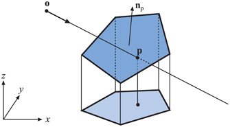
Figure 22.15. Orthographic projection of polygon vertices and intersection point onto the xy-plane, where the area of the projected polygon is maximized. This is an example of using dimension reduction to obtain simpler calculations.
The question left is whether the two-dimensional ray/plane intersection point is contained in the two-dimensional polygon. Here, we will review just one of the more useful algorithms—the “crossings” test. Haines [642] and Schneider and Eberly [1574] provide extensive surveys of two-dimensional, point-in-polygon strategies. A more formal treatment can be found in the computational geometry literature [135,1339,1444]. Lagae and Dutré [955] provide a fast method for ray/quadrilateral intersection based on the Möller and Trumbore ray/triangle test. Walker [1830] provides a method for rapid testing of polygons with more than 10 vertices. Nishita et al. [1284] discuss point inclusion testing for shapes with curved edges.
22.9.1. The Crossings Test
The crossings test is based on the Jordan Curve Theorem, a result from topology. From it, a point is inside a polygon if a ray from this point in an arbitrary direction in the plane crosses an odd number of polygon edges. The Jordan Curve Theorem actually limits itself to non-self-intersecting loops. For self-intersecting loops, this ray test causes some areas visibly inside the polygon to be considered outside. This is shown in Figure 22.16. This test is also known as the parity or the even-odd test.

Figure 22.16. A general polygon that is self-intersecting and concave, yet all its enclosed areas are not considered inside (only brown areas are inside). Vertices are marked with large, black dots. Three points being tested are shown, along with their test rays. According to the Jordan Curve Theorem, a point is inside if the number of crossings with the edges of the polygon is odd. Therefore, the uppermost and the bottommost points are inside (one and three crossings, respectively). The two middle points each cross two edges and are thus considered outside the polygon.
The crossings algorithm works by shooting a ray from the projection of the point in the positive x-direction (or in any direction; the x-direction is simply efficient to code). Then the number of crossings between the polygon edges and this ray is computed. As the Jordan Curve Theorem proves, an odd number of crossings indicates that the point is inside the polygon.
The test point can also be thought of as being at the origin, and the (translated) edges are tested against the positive x-axis instead. This option is depicted in Figure 22.17. If the y-coordinates of a polygon edge have the same sign, then that edge cannot cross the x-axis. Otherwise, it can, and then the x-coordinates are checked. If both are positive, then the number of crossings is incremented, since the test ray must hit this edge. If they differ in sign, the x-coordinate of the intersection between the edge and the x-axis must be computed, and if it is positive, the number of crossings is incremented.
In Figure 22.17 all enclosed areas could be categorized as inside as well. This variant test finds the winding number, the number of times the polygon loop goes around the test point. See Haines’ article [642] for treatment.

Figure 22.17. The polygon has been translated by ( is the point to be tested for containment in the polygon), and so the number of crossings with the positive x-axis determines whether is inside the polygon. Edges , , , and do not cross the x-axis. The intersection between edge and the x-axis must be computed, but will not yield a crossing, since the intersection has a negative x-component. Edges and will each increase the number of crossings, since the two vertices of each edge have positive x-components and one negative and one positive y-component. Finally, the edges and share a vertex where and , and they will together increase the number of crossings by one. By considering vertices on the x-axis as above the ray, is classified as crossing the ray, as above the ray.
Problems might occur when the test ray intersects a vertex, since two crossings might be detected. These problems are solved by considering the vertex infinitesimally above the ray, which, in practice, is done by interpreting the vertices with as also lying above the x-axis (the ray). The code becomes simpler and speedier, as then no vertices are intersected [640].
The pseudocode for an efficient form of the crossings test follows. It was inspired by the work of Joseph Samosky [1537] and Mark Haigh-Hutchinson, and the code is available on the web [642]. A two-dimensional test point and polygon P with vertices through are compared.

Line 3 checks whether the y-value of the last vertex in the polygon is greater than or equal to the y-value of the test point , and stores the result in the boolean . In other words, it tests whether the first endpoint of the first edge we will test is above or below the x-axis. Line 7 tests whether the endpoints and are on different sides of the x-axis formed by the test point. If so, then line 8 tests whether the x-intercept is positive. Actually, it is a bit faster than that: To avoid the divide normally needed for computing the intercept, we perform a sign-canceling operation here. By inverting inside, line 9 records that a crossing took place. Lines 10 through 12 move on to the next vertex.
In the pseudocode we do not perform a test after line 7 to see whether both endpoints have larger or smaller x-coordinates compared to the test point. Although we presented the algorithm with using a quick accept or reject of these types of edges, code based on the pseudocode presented often runs faster without this test. A major factor is the number of vertices in the polygons tested—with more vertices, checking the x-coordinate differences first can be more efficient.
The advantages of the crossings test is that it is relatively fast and robust, and requires no additional information or preprocessing for the polygon. A disadvantage of this method is that it does not yield anything beyond the indication of whether a point is inside or outside the polygon. Other methods, such as the ray/triangle test in Section 22.8.1, can also compute barycentric coordinates that can be used to interpolate additional information about the test point [642]. Note that barycentric coordinates can be extended to handle convex and concave polygons with more than three vertices [474,773]. Jiménez et al. [826] provide an optimized algorithm based on barycentric coordinates that aims to include all points along the edges of the polygon and is competitive with the crossings test.
The more general problem of determining whether a point is inside a closed outline formed of line segments and Bézier curvescurves!Bézier can be performed in a similar fashion, counting ray crossings. Lengyel [1028] gives a robust algorithm for this process, using it in a pixel shader for rendering text.
22.10 Plane/Box Intersection
We can know the distance of a point to a plane by inserting the point into the plane’s equation, . The absolute value of the result is the distance to the plane. Plane/sphere testing is then simple: Insert the sphere’s center into the plane equation and see if the absolute value is less than or equal to the sphere’s radius.
One way to determine whether a box intersects a plane is to insert all the vertices of the box into the plane equation. If both a positive and a negative result (or a zero) is obtained, then vertices are located on both sides of (or on) the plane, and therefore, an intersection has been detected. There are smarter, faster ways to do this test, which are presented in the next two sections, one for the AABB, and one for the OBB.
The idea behind both methods is that only two of the eight corners need to be inserted into the plane equation. For an arbitrarily oriented box, intersecting a plane or not, there are two diagonally opposite corners on the box that are the maximum distance apart, when measured along the plane’s normal. Every box has four diagonals, formed by its corners. Taking the dot product of each diagonal’s direction with the plane’s normal, the largest value identifies the diagonal with these two furthest points. By testing just these two corners, the box as a whole is tested against a plane.