
5
Acousto‐Optic Switches
Sudipta Ghosh1, Chandan Kumar Sarkar1, and Manash Chanda2
1 Department of Electronics and Telecommunication Engineering, Jadavpur University, Kolkata, West Bengal, India
2 Department of Electronics and Communication Engineering, Meghnad Saha Institute of Technology, Kolkata, West Bengal, India
5.1 Introduction
Acoustic‐optic switches are made based on the principles of diffraction of light through a propagating medium having periodical variation of refractive index. This index variation could formulate moving index grating or standing index grating, through the medium, caused by moving or standing acoustic wave respectively. The period and degree of modulation of index grating can be tuned by the frequency and amplitude of the acoustic wave through a transducer, controlled by electronic signals. A radio frequency (RF) electric field is applied across the electrodes of an acoustic transducer to generate an acoustic wave by piezoelectric effect. This acoustic wave induces a cyclical strain in the desired medium either on its surface to create surface acoustic wave (SAW) or in the bulk of that medium to create a bulk acoustic wave. Optical switches, couplers, frequency shifters, beam deflectors, and modulators have widely emerged as applications of acoustic‐optic devices in recent times.
Compound semiconductors using III‐V materials [1], like indium gallium arsenide or gallium phosphide, are desired candidates to construct acousto‐optic devices as these are popular in manufacturing monolithic ICs. These are most suitable materials for producing optical wave guides, lasers, and photodetectors. However, the driving power, diffraction efficiency, and piezoelectric properties of these materials are not good enough to build acousto‐optic devices. In a mean time lithium niobate (LN or LiNb03) [2] has emerged as a potential candidate in this domain for its excellent piezoelectric property. A well‐defined fabrication process with LN makes this material quite suitable for future AO switches and includes low‐loss waveguides, frequency selective optical switches, wavelength division multiplexing switches (WDM), and networks.
5.2 Fundamentals of Acousto‐Optic Effect
Photo‐elastic effect is defined as the change of optical properties of the supportive medium on appliance of mechanical strain. The principle of acousto‐optics is based on the phenomenon of the time‐dependent periodic variations of the optical property of the medium affected through a mechanical strain delivered by acoustic wave, i.e., photo‐elastic effect is the main cause of acousto‐optic phenomenon [3]. The strain causes the variation of refractive index of the medium, which can be expressed by the following equation:
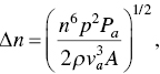
where n = refraction index of the supportive medium
p = suitable component of photo‐elastic tensor
Pa = total acoustic power (in Watts)
ρ = mass density
va = acoustic velocity
A = cross‐sectional area of the supportive medium through which the wave propagates;
Equation 5.1 can be rewritten as

where M2 is known as “figure of merit of Acousto‐Optics” and is expressed as [4]

The constituent parameters of M2 are subject to mode operations and the figure of merit as well. Both are dependent upon the polarizing mode and the direction of propagation of the acoustic wave and the polarization of the optical wave as well. The unit of figure of merit is cubic seconds per kilogram, which is equal to square meters per watt. The property of acoustic attenuation of material, due to acoustic absorption, is a considerable factor for many practical cases. The degree of attenuation increases with the square of sound frequencies. This phenomenon limits the use of materials like silica glass, TeO2, PbMoO4, and Ge etc. in any application below 1 GHz (typically between 10 and 500 MHz). Gallium phosphide (GaP) has a better use in mid‐acoustic frequency range, typically between 500 MHz and 1 GHz. LiNbO3 is very popular for the high‐acoustic frequency range, typically up to 5 GHz.
Many crystals, for example LiNbO3 and TeO2, are interested in acousto‐optic applications for their piezoelectric property. The coefficients of such elasto‐optic crystals are interchangeable with a piezoelectric effect due to the fact that the acoustic wave can create an electric field in the crystal, which also causes the conversion of the index to the crystal by electro‐optic effect. Correction for this second result can be very important for certain crystals. This conversion depends on the direction of acoustic wave propagation. In addition, they can rotate the ellipsoid index as well, creating decay, as unthinkable from previous experience and the effect of Pockels [5]. A complete description of the photo‐elastic effect has to include the contributions from both strain and rotation. Therefore, to treat the acousto‐optic diffraction through coupled‐wave theory [6] one needs to consider the photo‐electric effect in a medium, due to strain and rotation, both in terms of change in the permittivity of the medium.
5.3 Acousto‐Optic Diffraction
The space and time‐dependent acoustic wave equation can be represented by
where K is the propagation constant and Ω is the angular frequency in radian. A standing wave is the combination of two similar waves propagating in opposite directions. Mathematically it can be expressed as follows:
The time‐ and space‐dependent permittivity of the medium changes introduced by the acoustic wave is given by
where the factor K counts on the propagation direction and polarization property of acoustic wave. Generally, Δέ, that is, the change of permittivity, is a function of strain and rotation, caused by the acoustic wave, the photo‐elastic coefficient of the medium, and the direction of the acoustic wave. It also depends on the polarization and frequency of the optical wave. However, it is independent of the factors, K and Ω. The interaction between the optical wave of frequency ω, and the incident medium having periodic variation of permittivity, given in (5.7), results in diffracted optical waves with frequencies ω ± Ω. If the process keeps occurring this will end up with an array of diffracted waves with frequencies ω ± nΩ, where n is a positive or negative integer and is referred as the “order of acousto‐optic diffraction.” Therefore, the frequency of the diffracted beam can be expressed as
where Equations 5.8 and 5.9 represent mathematically the diffracted beam with upshifted and downshifted frequency respectively, as shown in Figure 5.1.
The total electric field can be expressed as a linear combination of all interacting components as follows
where all the wave components, having frequencies ωn= ω+nΩ, are associated with a single wave vector kn. Therefore, the coupled efficiency among the optical wave components of varying frequencies can be attributed as follows:
- Neighboring optical frequency components are separated by an amount of ±ω value.
- The efficiency of the coupling relies on the direction of propagation and the polarization of the optical waves, being coupled, and the acoustic wave as well.
- Coupling is possible between different polarized optical wave components in anisotropic and isotropic medium as well. The nature of Δέ is anisotropic itself. For an isotropic medium, coupling is possible provided p11 ≠ p12, i.e., the independent elements of the said medium should not be matched.
- The amount of phase mismatch between two wave components is the governing factor of the coupling efficiency in any coupling process. The phase‐match conditions between En, En−1 and En+1 are: kn−1 = kn−K and kn+1 = kn+K respectively.
Therefore, different diffraction phenomena are observed under different experimental condition, which are the main driving force for different application fields.
Figure 5.1 (a) Upshifted diffraction phenomenon. (b) Downshifted diffraction phenomenon.
5.4 Raman–Nath Diffraction
The Raman–Nath diffraction phenomenon is demonstrated in Figure 5.2(a) [7], where a plane optical wave of frequency ω gets diffracted by an acoustic column while travelling through a isotropic medium. It is considered that the propagation direction of the acoustic wave along the x‐axis, as shown in the figure, and the propagation direction of the incident optical wave is normal or near normal to the acoustic wave propagation path, i.e., along the z‐axis. θi is a small angle of diffraction with respect to the Z direction. The acoustic wave is considered to have a finite width in the Z direction and an infinite length in the X direction. It is also considered that there is no component of interaction along Y‐direction, i.e. the interaction between two waves is purely two‐dimensional. Here θn is the directional angle of kn, the wave vector, with respect to the Z‐axis. If l be the interaction length along the Z direction, and its value be so small as to satisfy the condition
Figure 5.2 (a) Raman–Nath diffraction phenomenon and (b) wave vectors.
then one can neglect the cumulative phase mismatch effect over the interaction length. This situation allows a number of diffraction orders through acousto‐optic coupling. This is known as Raman–Nath diffraction regime. The condition for Raman–Nath diffraction is given as
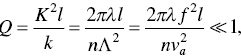
where the typical value of Q be lesser than equal to 0.3 for the Raman–Nath diffraction regime.
5.5 Bragg Diffraction
Optical diffraction by acoustic column causes either an array of diffracted beams or a single one, depending on refractive index, wavelength and the acousto‐optic interaction length [8]. Raman–Nath diffraction usually causes an array of beams, whereas the Bragg diffraction phenomenon generates a single beam of diffraction. Owing to higher diffraction efficiency, the Bragg diffraction is more popular for a wide range of applications.
The condition for Bragg’s refraction is such that the interaction length is large enough to satisfy the condition below:
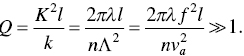
Here, one cannot neglect the cumulative phase mismatch effect over the interaction length. In order to have higher “diffraction efficiency”, the coupled wave components should have perfect or near‐perfect phase matching and this is the condition for Bragg diffraction. The typical vale of Q is more than equal to 4π for Bragg diffraction phenomena. The condition for phase matching is given as
where d and i stand for diffracted wave and incident wave respectively. The ±sign refers to frequency upshift and downshift phenomena respectively. The vector diagram of the Bragg diffraction is shown in Figure 5.3. The Bragg angle is given by
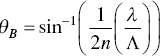
Figure 5.3 (a) Bragg diffraction phenomenon and (b) wave vectors.
5.6 Principle of Operation of AO Switches
The operation of AO switches is based on the principle of optical beam deflection or the collinear mode conversion. Figure 5.4 represents the basic operation of a 2×2 switch based on the principle of acousto‐optic beam deflector (AOBD) in cross and bar states. In the cross state, the output beam is obtained from the output port O1 (port O2) with the input beam entered through port I2 (port I1), without any deflection since no radio frequency signal is applied. In bar state, the input beam, entered through input port I1 (port I2), is deflected and routed through output port O1 (port O2), following the principle of Bragg deflection. Such guided‐wave acousto‐optic switches are usually made of gallium arsenide, indium phosphide, and lithium niobate etc. [9].
The block diagram of a collinear polarization principle based acousto‐optic switch is depicted in Figure 5.5. An acousto‐optic polarization converter (AOPC) and a pair of identical polarizing beam splitters (PBS) are used to construct the switch. The system functions according to the polarization diversity concept, similar to the LN‐based polarization‐independent scheme applicable for tunable filters [10]. The first splitter dissolves the incident polarized monochromatic light beams into two orthogonal components, known as vertical (V) and horizontal components. Therefore, the switch routed the H polarized beam from upper (lower) input towards lower (upper) output and V polarized beam from upper (lower) input to upper (lower) output port. Here a bar‐state switch and a cross‐state switch is depicted in Figure 5.6 (a) and (b) respectively. For the bar‐state switch, polarization conversion doesn’t take place as radio frequency control is absent. Therefore, signal is routed from input port I1 to output port O1 and from input port I2 to output port O2. For a cross‐state switch, on a contrary, the applied radio frequency assists the AOPC to rotate the linear polarization orthogonally, followed by a second PBS at the output end, acts as a beam combiner. Therefore, the switching system guides the signal from I1 to O2 and from I2 to O1 respectively.
Figure 5.4 Acousto‐optic beam deflector based optical switch (a) cross state and (b) bar state.
Figure 5.5 Block diagram of polarization‐independent acousto‐optic switch (a) cross state and (b) bar state.
Figure 5.6 Making of (a) all‐fiber switch and (b) acousto‐optic null coupler.
The quest for low‐power, low insertion loss, and low‐cost acousto‐optic switch ends up with the all‐fiber‐made single‐mode fused taper coupler. The coupler is known as null coupler [11, 12]. The coupler is constructed with two optical fibers with diameters, having difference to a such extent, that not to couple any light beam in the resultant coupler. It is implemented by pre‐tapering one of the two fibers through a short length before both the fibers get fused and extended. Therefore, a 2×2 switch is constructed with identical single‐mode ports. In the waist of the coupler, the fundamental mode is exited with one input beam, while the second mode is exited with the second input beam. However, an acoustic wave attunes the refractive index of the waist, resulting the input beam is guided to the second fiber due to the mode conversion, taken place at the waist of the coupler and this happens when the resonance occurs and is known as cross‐state. In bar state, the beam from one fiber is guided to the output of the same fiber as no acoustic wave is there to influence it. An all‐fiber acousto‐optic switch with insignificant polarization sensitivity, improved drive power, lower switching time, and insertion loss has achieved this by twisting the waist of a taper‐null‐coupler.
5.7 Acousto‐Optic Modulator
An acousto‐optic modulator is an electronically controlled amplitude modulator which modulates the intensity of an acoustic wave. The diffraction efficiency of an acousto‐optic modulator depends on the intensity of the acoustic wave. Therefore, it is an amplitude modulation of optical beam by acoustic wave. An acousto‐optic modulator (AOM) operates in a Raman–Nath regime or in a Bragg regime. The first‐order diffraction efficiency of a Raman–Nath modulator is equal to the diffraction efficiency of a Bragg cell, in low efficiency range.
There are certain disadvantages of a Raman–Nath‐modulator over a Bragg‐type modulator. First, the diffraction efficiency of the Raman–Nath type modulator is not more than 34%, even with the highest order of diffraction phenomena. On the contrary, the Bragg cell can attain 100% diffraction efficiency in a phase‐matched operational condition. The interaction length, l, in a Raman–Nath type modulator is quadratically related with the acoustic frequency and linearly related with the optical wavelength. Hence, a very high acoustic frequency and a fairly high optical wavelength can only result in a significant interaction length. Therefore, a Raman–Nath type modulator is restricted to small bandwidth operations. Bragg cells are free from these limitations.
Acousto‐optic modulators (AOM) have a wide range of applications. Previously, AO modulators were used in laser printers. The simple, low‐cost AOMs were the popular choice for building the external modulator for laser printers, before the implementations of organic photo‐resistors. AO devices have a unique application in combined operations as beam deflector and modulator in dither scanners.
Laser modulation in the infrared range has been another application domain of AOM. One important application is the use of AOM in laser communication as external modulator. Effective infrared AO materials cause a variety of laser modulation techniques with a large bandwidth, ranging from 1.06 μm to 10.6 μm. AO devices are preferred more than EO modulators in lower modulation bandwidth range, due to their low insertion loss. AOM are also used in CO2 lasers for the applications of precision matching, range finding, and communications.
AO modulators are extensively used inside laser cavities, which is applicable for Q‐switch, mode locking, and cavity dumping. Q‐switching of YAG lasers has been a critical role in industrial laser applications. An intracavity AO modulator is required in Q‐switching to maintain an insertion loss suitable for laser, to be kept below a threshold. Currently, UV grade fused silica is the most popular choice as an interaction medium for AO‐based Q‐switches, for their low optical absorption coefficient, good homogeneity, and lower strain‐free materialistic properties.
A standing wave AOM is required inside the cavity to provide a loss modulation at a frequency equivalent to the longitudinal mode spacing, in mode‐locking applications. The loss modulation causes a phase locking in longitudinal mode to generate short optical pulses. The cavity dumping is used to increase the repetition rates, which is constricted by the build‐up time of the population inversion in a Q‐switch. Appreciable research efforts have been delivered recently to AO devices, performing simultaneous operation of Q‐switching with mode locking or cavity damping.
5.7.1 Acousto‐Optic Q‐Switching
Q‐switching is a technique of generating high energy pulses of nanosecond order within solid‐state lasers. The switch is placed inside a laser resonator. A high‐power laser pulse is generated when the RF input of a laser resonator is turned off. A solid‐state laser required high switching speed and/or high loss modulators. The brief operational principle [13] is demonstrated in the following literature.
The transducer, made of molten quartz, is activated with the RF source. The incident light is diffracted from the axis of laser optical resonator with low loss and suppressed oscillation. Meanwhile, Nd:YAG has been pumped continuously. Consequently, the accumulated energy is released in a form of high‐power Q‐switched pulses (i.e., the status of Q‐value is high), as depicted in Figure 5.7, when the RF input is withdrawn.
Q‐switched Tm+3 silica fiber laser is reported [14] to have a wavelength of 2 μm, when pumped with a Nd:YAG laser, operating at 1.319 μm frequency. The Q‐switched laser is operated in the range of 2.9 m to 0.5 m and have the average laser output of 60 mW with a repetition frequency of Q‐switching at 100–500 Hz. The shortest pulse width of 150 ns is obtained with 4.1 kW of maximum peak power, which is the highest value, reported to date [15–19] for a similar kind of device operating in low‐order mode. An acousto‐optic Q‐switched Nd:YAG laser, operating at 1319 nm is recorded [20] to have highest peak power of 95 kW achieved with pulse duration of 150 ns and pulse repetition frequency of 5 kHz and 12.8% optical conversion efficiency. The conversion efficiency got even better, reached 17%, its highest value, assisted with pumping power of 555 W. Average output power is recorded as 94 W at 50 kHz PRF. Gold nano‐rod (GNR) has been exploited as a saturated absorber (SA) for the first time [21] in a Q‐switched Nd:YAG laser to obtain maximum pulse energy of 19 μJ at pulse repetition rate of 20 kHz.
AO Q‐switched TEM00 grazing angle laser with ultra‐high repetition frequency is realized [22] to have 2.1 MHz switching speed at average output power of 8.6 W and 2.2 MHz switching speed at average power of 10 W. The Nd:YVO4 crystal is 3 at.% neodymium doped. The tolerance limit of the energy pulses is less than +/−6.7 % and +/−6.9 % at PRF of 2 MHz. Self‐Raman multi‐stokes Q‐switched laser, working around 1.2 to 1.3 μm, is demonstrated in a c‐cut Nd:YVO4 crystal. Stokes emission is observed from 1215 nm to 1316 nm range in sequences. 17.1 W of pumping power is obtained at 10 kHz PRF. Average output is registered as 1.02 W for multi‐stokes operation, resulting a slope efficiency of 9.1%. To ascertain high peak power, an AO‐Q‐switched HO:Y2O3 ceramic laser, operating at 2117 nm, pumped with fiber laser source at 1931 nm, is realized [23]. Average output power of more than 20 W is recorded at PRF of 10 kHz. Corresponding pulse energy is 2.0 mJ with a pulse duration of 33.1 ns and highest peak power of 60 kW. Search for further improvements on output performance is still under process.

Figure 5.7 Schematic view of an acousto‐optic modulator.
5.7.2 Telecommunication Network
Cross‐bar optical switch architecture using multichannel Bragg cell on GaAs substrate exhibits polarization‐insensitive switching with low crosstalk, low insertion loss, and minimum access time [24]. A typical acousto‐optic Bragg cell is shown in Figure 5.8. Multiple electrodes are constructed in a close proximity, on a common acoustic substrate. The design must consider the constraint of thermal budget, crosstalk limit, and figure of merit of the acousto‐optic materials. In Bragg cell‐based acousto‐optic switches, interactive photons have to travel through an array of such cells in the system.
Wave division multiplexing (WDM) technique based optical telecommunication network has been a diverse domain of research for the last couple of decades. A WDM‐based telecom switching system is investigated through add‐drop and equalization functionalities, implemented in TeO2, where trade‐off has been made between spectral resolution of the device and AO figure of merit of the material for the sake of better filter performance [25]. The functionalities are implemented for all‐fiber AO devices and TeO2 is considered as AO material for its high value of figure of merit (M2). Studies reveal that 40 mW average power is desirable for 100% selective deflection of light or intensity attenuation of 30 dB. Sidelobes have been suppressed for 1.55 μm wavelength. Three signals, to be multiplexed, are spaced by 1, 2, and 4 nm in input fiber for experimental setup of bar state and cross state as well. The system is proved to be completely insensitive to polarization. TeO2 deflector based 2×2 optical switch/ multi‐transducer is implemented through couple‐mode arrangement of two, phase grating crystals [26]. The switch is attributed with 50‐dB crosstalk, polarization sensitivity less than 0.5 dB and response time of less than 200 ns.
Figure 5.8 Schematic view of a multichannel Bragg cell.
A dynamic optical fiber add‐drop multiplexer (OADM) is demonstrated based on principle of Bragg grating and AO effect [27]. The device possesses the virtue of minimum response time about 95 μs with a future technological projection of minimum leakage about −25 dB and response time about 50 μs and even less. Recent advancement on optical fiber laser is registered, that emits 17 wavelengths simultaneously, covering the entire C band [28]. Chromatic dispersion of the filter in optical network is measured using time flight method to justify the reliability of the laser source.
Mode division multiplexing (MDM) is one of the leading research trends in telecommunication network [29]. A highly efficient AO generator is realized for selective mode conversion from lower to higher‐order modes for a few‐mode fiber (FMF). The converter possesses 90% coupling efficiency and more than 10 dB extinction ratio for all higher‐order modes, consisting of LP01, LP11, LP21, and LP02 in a four‐mode fiber. It proclaims a consistent response for step‐index fiber. A novel Brillouin fiber sensor is reported [30] based on M‐shaped single‐mode fiber for performance analysis regarding temperature and strain sensing. Results revealed high accuracy, owing temperature error of 0.4 °C & strain error of 12.3 με. The sensing technique has utmost potential to be implemented in diversified fields. A fiber‐optic array of accelerometer has been implemented using dual heterodyne phase sensitive optical time domain reflection (OTDR) concept [31]. Sensitivity about 36 rad/g is achieved subject to the system architecture design, consisting of three accelerometers spaced by 20 m in a single optical fiber in multiplexing mode. In this way, common mode noise is suppressed by 35 dB at a frequency of 100 Hz, which is a significant achievement in telecom domain.
5.8 Recent Trends and Applications
5.8.1 Emerging Spatial Mode Conversion in Few‐Mode Fibers
Acousto‐optic conversions in few‐mode fibers have been emerged as a possible solution for the constraints of the conventional spatial mode switching devices. It enhances the switching capabilities and fast mode tuning in special mode through microwave signal modulated acousto‐optic mode conversions. This effect endorses novel applications of dynamic mode controlled high‐order mode fiber lasers, which finds diverse applications in the domain of optical communications, optical tweezers, laser manufacturing, structured light imaging etc. Spatial modes, consisting of cylindrical vector mode (CVM), linear polarization, and optical vortex mode, enhances the stability in optical fiber by a distributed electric field. For an ever‐growing network traffic, this dynamic mode operation holds the sustainability of future communication system through spatial division multiplexing (SDM).
The quality of optical sources typically lies on the dynamic mode controlled spatial higher‐order modes (HOM). Long‐period grating (LPG), Fiber Bragg grating (FBG), photonic lanterns, and mode selective couplers (MSC) are the end product as applications of the spatial mode through static method in fiber‐optics. MSC exhibits mode coupling through tapering fused fibers, where a single‐mode fiber (SMF) is combined with a few‐mode fiber (FMF) to construct MSC in order to obtain the HOMs from Gaussian‐like fundamental mode [32].
Photonic lanterns are integral part of some specific HOMs, offering mode switching with low crosstalk and quite suitable for SDM technology [33]. The process of refractive index grating in fiber‐optic generates mode conversions from forward propagating mode to either forward‐propagating HOMs or backward‐propagating HOMs in LPGs and FBGs respectively. But these applications are limited to HOMs unless a dynamic mode of switching is applied for spatial higher‐order modes.
Acoustically modulated fiber‐optic grating in optical fiber generates a high switching speed spatial mode in acousto‐optic mode converters (AOMC). This is first reported and demonstrated by Kim et al. in 1986, with an AOMC based on a couple of mode fibers. Later, based on this unique concept, acoustic‐optic interaction (AOI), various components have been derived. All‐fiber acousto‐optic tunable filters with low loss, optimum bandwidth, and reduced crosstalk problem is reported in the literatures [34–38]. More researches have been carried out on optimization the polarization sensitivity, utilization of tapered, and micro‐tapered optical fiber and several structural modifications in filter design [39–47].
Different superlattice modulators based on acousto‐optic Bragg grating phenomena have been reported in many literatures [48–52] as another application domain. The heterodyne detection/ demodulation during the mode conversion of the frequency shifter [53–56] provides the vibration information under study. Photonic crystal fiber‐based AOI devices [57–60], wavelength tunable lasers [61–65], AOCM‐based ultrafast fiber lasers [66–75], and vector mode generators [76–80] have been potential research areas for the last couple of decades while exploring the device characterizations based on acousto‐optic interactions. The acousto‐optical birefringence with novel mechanisms, adopted in elliptic core FMF in recent times, have been supported to implement successfully the dynamic mode switching via FSK. This phenomenon has emerged as a potential technique in dynamic optical tunning for HOM lasers [81–87] and spatial mode‐locking mechanism research [88].
However, in future, this research area will explores the time domain and spatial domain response of the nonlinear interaction between optical solitons and microwave signals. Multiple spatial mode inside the ML laser cavity introduces a new dynamic switching of mode conversion, which results in evolutionary spatial mode applications in HOM ML lasers. Advance studies have made it possible for AOMCs to integrate stimulate and depletion sources and super diffraction imaging. OAM mode operation in optical tweezers introduces the particle control to implement optical moving, catching, and rotation as well. The constraint regarding the controllability of the proportion of multi‐HOMs has been mitigated through dynamic efficiency control of AOMCs. AOMC is a prospective approach in fabricating high‐power lasers.
5.8.2 Lithium Niobate Thin Films
In the mid‐90s, lithium niobate has been evolved as a prospective substrate material, best suited to integrated optic fabrication, for its acousto‐optic and piezoelectric figure of merit [11]. An integrated acousto‐optic switch with LiNbO3 was reported, based on the principle of polarization conversion [89]. Like TE mode and TM mode, for two orthogonally polarized beams, two parallel Ti waveguides were fabricated. An unpolarized input beam is fragmented into two orthogonal components. At the output, the components are reunified and guided towards a particular output through a X‐junction. A single‐mode Ti waveguide is formed by indiffusion process for 10 hrs at 1050 °C. Acoustic barriers are fabricated by the same process, stated above, for 20 hrs of diffusion. The figure depicts a single‐mode SAW waveguide with 100 μm spanning. Thermal diffusion is a well‐known process to fabricate high‐quality Ti:LiNbO3 waveguides for acousto‐optic switching. Most of the integrated acousto‐optic switches are fabricated using x‐cut, y‐propagation with optical axis towards the z direction.
Lithium niobate has emerged as a potential candidate in the field of optoelectronics for the last couple of decades. It is popularly known as the “silicon of photonics” due to its novel acousto‐optic, piezoelectric, and nonlinear (NL) properties. The nonlinear property has a natural dependency on the crystal orientation, i.e., poling orientation or domain. Frequency conversion, micro‐phonon polariton excitation, and polarization rotation have been extensively studied through periodically‐poled lithum niobate (PPLN). Introducing different physical process with domain engineering (DI) results in polarization‐independent frequency conversion. Recently, commercially available LN thin film on Insulator (LNOI) made it possible to boost the packaging density of photonic devices and circuits. LNOI is a thin film LN over SiO2/Ln substrate, like silicon‐on‐insulator (SOI) structure. The top LN film is x‐cut or z‐cut, having dimension of nm order. Two domain poling techniques has been experimented over micro‐thick (~28 um) and sub‐micro‐thick (~540 nm) LNOI structure. Micron‐thick PPLNOI was fabricated successfully and no domain back switching was experienced even after 35 days. For a submicron‐thick sample the period is only for 25 hours and 50% of negative domain area could be sustained.
DI has a wide range of applications regarding quasi‐phase‐matched harmonic generators, optical parametric oscillators, and wavelength division multiplexing (WDM) frequency conversions. More recently, applications of DI have been exploited for large BW and low‐voltage driving modulators, single sideband modulators, and bulk and surface acoustic waves with uniform electrodes.
5.8.3 Optical Fiber Communication and Networking
Light wave synthesized frequency sweeper (LSFS), an acousto‐optic switch, is realized for wavelength division multiplexing (WDM), based on a chromatic dispersion method. Introducing lock‐in detection and phase diversion technique in LSFS while measuring group delay results in fast measurement time, brilliant wavelength resolution, and high wavelength accuracy. The accuracy of frequency and the resolution of group delay are found about +/− 100 MHz and 8 ps respectively under experimental optical frequency range of 800 GHz, which could have further extended up to 4 THz by controlling the centre frequency of the BPF [90].
A novel all‐fiber AO switch, constructed with AO tunable filters and mode selective couplers, is demonstrated with a two‐mode fiber design [91]. The switch exhibits 2 dB or less operational loss in an operating bandwidth of 50 nm and more. The 3 dB bandwidth of the switched signal could be varied from 2.5 nm to 35 nm and even more. The extended work is a realization of optical add‐drop multiplexer by this AO switch, which enhances the merit of this work to a great extent.
All‐fiber acoustic tunable filters (AOTFs) are widely applicable for narrowband optical add‐drop multiplexer (AODM) system, tunable bandpass filters (BPF), and WDM applications in optical communication field. A typical narrowband filter is designed [92] to have very low polarization sensitivity, owing to 3 dB bandwidth of 0.8 nm and interaction length of 10 cm.
A programable RF filter, designed for broadband range, is constructed with digital micro‐mirror devices (DMD), acousto‐optic tunable filter (AOTF), and a chirped fiber Bragg grating (CFBG). The filter is attributed to select higher number of taps, compared to the conventional ones. The filter nulls [93], registered at 6.90, 6.945, and 6.99 GHz for a three‐tap design, proves its precision tunability property, which can enhance the stop‐band and passband characteristics of the filter.
Research on acoustic sensor‐based applications is carried out by exploring the distributed acoustic sensing (DAS) and distributed temperature sensing (DTS) simultaneously [94]. The DAS based on FDM and time‐gated digital OFDR [95] resolved the trade‐off between spatial resolution and maximum measurement distance and vibration response bandwidth and measurement distance as well. Two parallel vibration frequencies up to 9 kHz are recorded over 24.7 km long fiber, having spatial resolution of 10 m and SNR of 30 dB in one experiment whereas in second one [96] the measurement distance is 108 km with spatial distance of 5 m is achieved by a DAS system architected with distributed Raman amplifier.
A novel all‐fiber mode converter frequency shifter (MCFS), based on mode selective coupler (MSC) and high‐order mode converter (HOMC), is realized [97] to successfully implement the mode conversion from LP11 to LP01 and parallelly acts as a frequency shifter. Vibration frequencies range from 1 kHz to 300 kHz with minimum detectable amplitude of 0.019 nm. Conversion of modes from LP01 to higher orders like LP11a/b and LP21a/b is also achieved [98] at the same resonant frequency, attributed to broadband tunability in mode conversion.
Bibliography
- 1 C.S. Tsai. Integrated acousto‐optic and magneto‐optic devices for optical information processing. Proceedings of IEEE, 84(6):853–869, 1996.
- 2 D.A. Smith, R.S. Chakravarthy, Z. Bao, J.E. Baran, J.J. Jackel, A. d’Alessandro, D.J. Fritz, S.H. Huang, X.Y. Zou, S.M. Hwang, A. Willner, and K.D. Li. Evolution of the acousto‐optic wavelength routing switch. Journal of Lightwave Technology, 14(6):1005–1019, 1996.
- 3 A. Yariv and P. Yeh. Optical Waves in Crystals. New York, John Wiley & Sons, 1984.
- 4 R.G. Hunsperger. Acousto‐optic modulators. In: R.G. Hunsperger, Integrated Optics: Theory and Technology. Springer Series in Optical Sciences, vol. 33, 144–157. Berlin, Heidelberg, Springer, 1984. doi: 10.1007/978‐3‐662‐13565‐5_9.
- 5 W.P. Mason. Optical properties and the electro‐optic and photo‐elastic effects in crystals expressed in tensor form. The Bell System Technical Journal, 29(2):161–188, 1950. doi: 10.1002/j.1538‐7305.1950.tb00464.x.
- 6 S.E. Miller. Coupled wave theory and waveguide applications. The Bell System Technical Journal, 33(3):661–719, 1954. doi: 10.1002/j.1538‐7305.1954.tb02359.x.
- 7 D.T. Pierce and R.L. Byer. Experiments on the interaction of light and sound for advanced laboratory. American Journal of Physics, 41:314, 1973. doi: 10.1119/1.1987217
- 8 M. Ahmed and G. Wade. Bragg‐diffraction imaging. Proceedings of the IEEE, 67(4):587–603, 1979. doi: 10.1109/PROC.1979.11285.
- 9 C.S. Tsai. Integrated acousto‐optic and magneto‐optic devices for optical information processing. Proceedings of IEEE, 84(6):853–869, 1996.
- 10 D.A. Smith, J.E. Baran, K.W. Cheung, and J.J. Johnson. Polarization independent acoustically tunable optical filters. Applied Physics Letters, 56(3):209–211, 1990.
- 11 T.A. Birks, D.O. Culverhouse, S.G. Farwell, and P. St. J. Russell. 2 x 2 Single‐mode fiber routing switch. Optics Letters, 21(10):722–724, 1996.
- 12 D.O. Culverhouse, T.A. Birks, S.G. Farwell, and P. St. J. Russell. 3 x 3 All‐fiber routing switch. IEEE Photonics Technology Letters, 9(3):333–335, 1997.
- 13 http://www.sintec.sg/products/ao/1286.html
- 14 A.F. El‐Sherif and T.A. King. Analysis and optimization of Q‐switched operation of a Tm3+‐doped silica fiber laser operating at 2 μm. IEEE Journal of Quantum Electronics, 39(6):759–765, 2003. doi: 10.1109/JQE.2003.811597.
- 15 P.R. Morkel, K.P. Jedrzejewski, E.R. Taylor, and D.N. Payne. Short pulse, high‐power Q‐switched fiber laser. IEEE Photonics Technology Letters, 4:545–547, 1992
- 16 Z.J. Chen, A.B. Grudinin, J. Porta, and J.D. Minelly. Enhanced Q‐switching in double‐clad fiber lasers. Optics Letters, 23:454–456, 1998.
- 17 C.C. Renaud, R.J. Selvas‐Aguilar, J. Nilsson, P.W. Turner, and A.B. Grudinin. Compact high‐energy Q‐switched cladding‐pumped fiber laser with a tuning range over 40 nm. IEEE Photonics Technology Letters, 11:976–978, 1999.
- 18 D.J. Richardson, P. Britton, and D. Taverner. Diode‐pumped, high energy, single transverse mode Q‐switch fiber laser. Electronics Letters, 33:1955–1956, 1997.
- 19 G.P. Lees, D. Taverner, D.J. Richardson, L. Dong, and T.P. Newson. Q‐switched erbium doped fiber laser utilising a novel large mode area fiber. Electronics Letters, 33:393–394, 1997.
- 20 H. Zhu, G. Zhang, C. Huang, Y. Wei, L. Huang, and Z. Chen. Diode‐side‐pumped acoustooptic Q‐switched 1319‐nm Nd:YAG Laser. IEEE Journal of Quantum Electronics, 44(5):480–484, 2008. doi: 10.1109/JQE.2008.916698.
- 21 H.T. Huang, M. Li, L. Wang, X. Liu, D.Y. Shen, and D.Y. Tang. Gold nanorods as single and combined saturable absorbers for a high‐energy q‐switched Nd:YAG solid‐state laser. IEEE Photonics Journal, 7(4):4501210. doi: 10.1109/JPHOT.2015.2460552.
- 22 X. Yan et al. 2 MHz AO Q‐switched TEM00 grazing incidence laser with 3 at. % neodymium doped Nd:YVO4. IEEE Journal of Quantum Electronics, 44(12):1164–1170, 2008. doi: 10.1109/JQE.2008.2003141.
- 23 E. Li, J. Tang, Y. Shen, F. Wang, J. Wang, D. Tang, and D.Shen. High peak power acousto‐optically Q‐switched Ho:Y2O3 ceramic laser at 2117 nm. IEEE Photonics Technology Letters, 32(8):492–495, 2020. doi: 10.1109/LPT.2020.2981642.
- 24 J. Sapriel, Vladimir Ya. Molchanov, G. Aubin, and S. Gosselin. Acousto‐optic switch for telecommunication networks. Proc. SPIE 5828, Acousto‐optics and Applications 3. doi: 10.1117/12.612841.
- 25 J. Sapriel, D. Charissoux, V. Voloshinov and V. Molchanov. Tunable acousto‐optic filters and equalizers for WDM applications. Journal of Lightwave Technology, 20(5):892–899, 2002. doi: 10.1109/JLT.2002.1007946.
- 26 V. Quintard, A. Perennou, and J. Aboujeib. Characterization of a 2×2 optical switch based on a multitransducers acousto‐optic deflector. IEEE Photonics Technology Letters, 21(24):1825–1827, 2009. doi: 10.1109/LPT.2009.2034538.
- 27 A. Diez, M. Delgado‐Pinar, J. Mora, J.L. Cruz, and M.V. Andres. Dynamic fiber‐optic add‐drop multiplexer using Bragg gratings and acousto‐optic‐induced coupling. IEEE Photonics Technology Letters, 15(1):84–86, 2003. doi: 10.1109/LPT.2002.805867.
- 28 J. Maran, R. Slavik, S. LaRochelle, and M. Karasek. Chromatic dispersion measurement using a multiwavelength frequency‐shifted feedback fiber laser. IEEE Transactions on Instrumentation and Measurement, 53(1):67–71, 2004. doi: 10.1109/TIM.2003.822008
- 29 D. Song, H. Su Park, B.Y. Kim, and K.Y. Song. Acousto‐optic generation and characterization of the higher order modes in a four‐mode fiber for mode‐division multiplexed transmission. Journal of Lightwave Technology, 32(23):4534–4538, 2014. doi: 10.1109/JLT.2014.2360936.
- 30 Y. Dong, G. Ren, H. Xiao, Y. Gao, H. Li, S. Xiao, and Shuisheng Jia. Simultaneous temperature and strain sensing based on m‐shaped single mode fiber. IEEE Photonics Technology Letters, 29(22):1955–1958, 2017. doi: 10.1109/LPT.2017.2757933.
- 31 X. He, M. Zhang, S. Xie, F. Liu, L. Gu, and D. Yi. Self‐referenced accelerometer array multiplexed on a single fiber using a dual‐pulse heterodyne phase‐sensitive OTDR. Journal of Lightwave Technology, 36(14):2973–2979, 2018. doi: 10.1109/JLT.2018.2830114.
- 32 H. Yao, F. Shi, Z. Wu, X. Xu, T. Wang, X. Liu, P. Xi, F. Pang, and Xianglong Zeng. A mode generator and multiplexer at visible wavelength based on all‐fiber mode selective coupler. Nanophotonics, 9(4):973–981, 2020.
- 33 X. Sai, Y. Li, C. Yang, Wei Li, J, Qiu, X. Hong, Y. Zuo, H. Guo, W. Tong, and J. Wu. Design of elliptical‐core mode selective photonic lanterns with six modes for MIMO‐free mode division multiplexing systems. Optics Letters, 42(21):4355–4358, 2017
- 34 D. Ostling and H.E. Engan. Spectral flattening by an all‐fiber acousto‐optic tunable filter. IEEE International Ultrasonics Symposium, 2(2):837–840, 1995.
- 35 D. Ostling and H.E. Engan. Acousto‐optic tunable filters in two mode fibers. Optical Fiber Technology, 3(2):177–183, 1997.
- 36 H.S. Kim, S.H. Yun, I.K. Kwang, and B.Y. Kim. All‐fiber acousto‐optic tunable notch filter with electronically controllable spectral profile. Optics Letters, 22(19):1476–1478, 1997.
- 37 D.O. Culverhouse, S.H. Yun, D.J. Richardson, T.A. Birks, S.G. Farwell, and P.St.J. Russell. Low‐loss all‐fiber acousto‐optic tunable filter. Optics Letters, 22(2):96–98, 1997.
- 38 I.K. Hwang, S.H. Yun, and B.Y. Kim. All‐fiber tunable comb filter with nonreciprocal transmission. IEEE Photonics Technology Letters, 10(10):1437–1439, 1998.
- 39 R. Feced, C. Alegria, M.N. Zervas, and R.I. Laming. Acousto‐optic attenuation filters based on tapered optical fibers. IEEE Journal of Selected Topics in Quantum Electronics, 5(5):1278–1288, 1999.
- 40 A. Diez, G. Kakarantzas, T.A. Birks, and P.S.J. Russell. Acoustic stop‐bands in periodically microtapered optical fibers. Applied Physics Letters, 76(23):3481–3483, 2000.
- 41 D.A. Satorius, T.E. Dimmick, and G.L. Burdge. Double‐pass acousto‐optic tunable bandpass filter with zero frequency shift and reduced polarization sensitivity. IEEE Photonics Technology Letters, 14(9):1324–1326, 2002.
- 42 W. Zhang, F. Gao, F. Bo, Q. Wu, G. Zhang, and J. Xu. All‐fiber acousto‐optic tunable notch filter with a fiber winding driven by a cuneal acoustic transducer. Optics Letters, 36(2):271–273, 2011.
- 43 W. Zhang, L. Huang, F. Gao, F. Bo, G. Zhang, and J. Xu. All‐fiber tunable Mach‐Zehnder interferometer based on an acousto‐optic tunable filter cascaded with a tapered fiber. Optics Communications, 292:46–48, 2013.
- 44 W. Zhang, L. Huang, F. Gao, F. Bo, G. Zhang, and J. Xu. Tunable broadband light coupler based on two parallel all‐fiber acousto‐optic tunable filters. Optics Express, 21(14):16621–16628, 2013.
- 45 H. Zhang, S. Kang, B. Liu, H. Dong, and Y. Miao. All‐fiber acousto‐optic tunable bandpass filter based on a lateral offset fiber splicing structure. IEEE Photonics Journal, 7(1):2700312, 2015.
- 46 G.R. Melendez, M. Bello‐Jimenez, O. Pottiez, and M. Andres. Improved all‐fiber acousto‐optic tunable bandpass filter. IEEE Photonics Technology Letters, 29(12):1015–1018, 2017.
- 47 L. Huang, W. Zhang, Y. Li, H. Han, X. Li, P. Chang, F. Gao, G. Zhang, L. Gao, and T. Zhu. Acousto‐optic tunable bandpass filter based on acoustic‐flexural‐wave‐induced fiber birefringence. Optics Letters, 43(21):5431–5434, 2018.
- 48 W.F. Liu, P.S.J. Russell, and L. Dong. Acousto‐optic superlattice modulator using a fiber Bragg grating. Optics Letters, 22(19):1515–1517, 1997.
- 49 W.F. Liu, P.S.J. Russell, and L. Dong. 100% efficient narrow‐band acousto‐optic tunable reflector using fiber Bragg grating. Journal of Lightwave Technology, 16(11):2006–2009, 1998.
- 50 P.S.J. Russell and W.F. Liu. Acousto‐optic superlattice modulation in fiber Bragg gratings. Journal of the Optical Society of America A, 17(8):1421–1429, 2000.
- 51 W. Liu, I. Liu, L. Chung, D. Huang, and C.C. Yang. Acoustic induced switching of the reflection wavelength in a fiber Bragg grating. Optics Letters, 25(18):1319–1321, 2000.
- 52 N. Sun, C. Chou, M. Chang, and C.‐N. Lin. Analysis of phase‐matching conditions in flexural‐wave modulated fiber Bragg grating. Journal of Lightwave Technology, 20(2):311–315, 2002.
- 53 W.J. Lee, B.K. Kim, K.H. Han, and B.Y. Kim. Dual heterodyne polarization diversity demodulation for fiber‐optic interferometers. IEEE Photonics Technology Letters, 11(9):1156–1158, 1999.
- 54 H.M. Chan, R. Huang, F. Alhassen, O. Finch, I.V. Tomov, C.‐S. Park, and H.P. Lee. A compact all‐fiber LPG‐AOTF frequency shifter on single‐mode fiber and its application to vibration measurement. IEEE Photonics Technology Letters, 20(18):1572–1574, 2008.
- 55 W. Zhang, W. Gao, L. Huang, D. Mao, B. Jiang, F. Gao, D. Yang, G. Zhang, J. Xu, and J. Zhao. Optical heterodyne microvibration measurement based on all‐fiber acousto‐optic frequency shifter. Optics Express, 23(13):17576–17583, 2015.
- 56 W. Zhang, Z. Chen, B. Jiang, L. Huang, D. Mao, F. Gao, T. Mei, D. Yang, L. Zhang, and J. Zhao. Optical heterodyne microvibration detection based on all‐fiber acousto‐optic superlattice modulation. Journal of Lightwave Technology, 35(18):3821–3824, 2017.
- 57 A. Diez, T.A. Birks, W.H. Reeves, B.J. Mangan, and P.S.J. Russell. Excitation of cladding modes in photonic crystal fibers by flexural acoustic waves. Optics Letters, 25(20):1499–1501, 2000.
- 58 M.W. Haakestad and H.E. Engan. Acousto‐optic properties of a weakly multimode solid core photonic crystal fiber. Journal of Lightwave Technology, 24(2):838–845, 2006.
- 59 M.W. Haakestad and H.E. Engan. Acousto‐optic characterization of a birefringent two‐mode photonic crystal fiber. Optics Express, 14(16):7319–7328, 2006.
- 60 K.S. Hong, H.C. Park, and B.Y. Kim. 1000 nm tunable acousto‐optic filter based on photonic crystal fiber. Applied Physics Letters, 92(3):031110, 2008.
- 61 M.S. Kang, M.S. Lee, J.C. Yong, and B.Y. Kim. Characterization of wavelength‐tunable single‐frequency fiber laser employing acousto‐optic tunable filter. Journal of Lightwave Technology, 24(4):1812–1823, 2006.
- 62 L. Huang, P. Chang, X. Song, W. Peng, W. Zhang, F. Gao, F. Bo, G. Zhang, and J. Xu. Tunable in‐fiber Mach Zehnder interferometer driven by unique acoustic transducer and its application in tunable multi‐wavelength laser. Optics Express, 24(3):2406–2412, 2016.
- 63 L. Huang, X. Song, P. Chang, W. Peng, W. Zhang, F. Gao, F. Bo, G. Zhang, and J. Xu. All‐fiber tunable laser based on an acousto‐optic tunable filter and a tapered fiber. Optics Express, 24(7):7449–7455, 2016.
- 64 N. Yan, X. Han, P. Chang, L. Huang, F. Gao, X. Yu, W. Zhang, Z. Zhang, G. Zhang, and J. Xu. Tunable dual‐wavelength fiber laser with unique gain system based on in‐fiber acousto‐optic Mach‐Zehnder interferometer. Optics Express, 25(22):27609–27615, 2017.
- 65 E.H. Escobar, M.B. Jimenéz, A.C. Avilés, R. López Estopier, O. Pottiez, M. Durán Sánchez, B. Ibarra Escamilla, and M.V. Andrés. Experimental study of an in‐fiber acousto‐optic tunable bandpass filter for single‐ and dual‐wavelength operation in a thulium‐doped fiber laser. Optics Express, 27(26):38602–38613, 2019.
- 66 D. Zalvidea, N.A. Russo, R. Duchowicz, M. Delgado‐Pinar, A. Diez, J.L. Cruz, and M.V. André. High‐repetition rate acoustic‐induced q‐switched all‐fiber laser. Optics Communications, 244(1–6):315–319, 2005.
- 67 M. Delgado‐Pinar, D. Zalvidea, A. Diez, P. Perez‐Millan, and M.V. Andrés. Q‐switching of an all‐fiber laser by acousto‐optic modulation of a fiber Bragg grating. Optics Express, 14(3):1106–1112, 2006.
- 68 C. Cuadrado‐Laborde, M. Delgado‐Pinar, S. Torres‐Peiró, A. Díez, and M.V. Andrés. Q‐switched all‐fibre laser using a fibre‐optic resonant acousto‐optic modulator. Optics Communications, 274(2):407–411, 2007.
- 69 C. Cuadrado‐Laborde, A. Diez, M. Delgado‐Pinar, J.L. Cruz, and M.V. Andrés. Mode locking of an all‐fiber laser by acousto‐optic superlattice modulation. Optics Letters, 34(7):1111–1113, 2009.
- 70 C. Cuadrado‐Laborde, A. Díez, J.L. Cruz, and M.V. Andrés. Experimental study of an all‐fiber laser actively mode‐locked by standing‐wave acousto‐optic modulation. Applied Physics B, 99(1–2):95–99, 2010.
- 71 M. Bello‐Jimenéz, C. Cuadrado‐Laborde, A. Diez, J.L. Cruz, and M.V. Andrés. Experimental study of an actively mode‐locked fiber ring laser based on in‐fiber amplitude modulation. Applied Physics B, 105(2):269–276, 2011.
- 72 C. Cuadrado‐Laborde, A. Diez, J.L. Cruz, and M.V. Andrés. Q‐switched and mode locked all‐fiber lasers based on advanced acousto‐optic devices. Laser & Photonics Reviews, 5(3):404–421, 2011.
- 73 M. Bello‐Jimenez, C. Cuadrado‐Laborde, A. Diez, J.L. Cruz, M.V. Andres, and A. Rodrıguez‐Cobos. Mode‐locked all‐fiber ring laser based on broad bandwidth in‐fiber acousto‐optic modulator. Applied Physics B, 110:73–80, 2013.
- 74 W. Zhang, K. Wei, H. Wang, D. Mao, T. Mei, J. Zhao, F. Gao, and L. Huang. Tunable‐wavelength picosecond vortex generation in fiber and its application in frequency‐doubled vortex. Journal of Optics, 20(1):014004, 2018.
- 75 Y. Li, L. Huang, H. Han, L. Gao, Y. Cao, Y. Gong, W. Zhang, F. Gao, I.P. Ikechukwu, and T. Zhu. Acousto‐optic tunable ultrafast laser with vector‐mode‐coupling‐induced polarization conversion. Photonics Research, 7(7):798–805, 2019.
- 76 P.Z. Dashti, F. Alhassen, and H.P. Lee. Observation of orbital angular momentum transfer between acoustic and optical vortices in optical fiber. Physical Review Letters, 96(4):043604, 2006.
- 77 W. Zhang, L. Huang, K. Wei, P. Li, B. Jiang, D. Mao, F. Gao, T. Mei, G. Zhang, and Jianlin Zhao. Cylindrical vector beam generation in fiber with mode selectivity and wavelength tunability over broadband by acoustic flexural wave. Optics Express, 24(10):10376–10384, 2016.
- 78 W. Zhang, K. Wei, L. Huang, D. Mao, B. Jiang, F. Gao, G. Zhang, T. Mei, and J. Zhao. Optical vortex generation with wavelength tunability based on an acoustically‐induced fiber grating. Optics Express, 24(17):19278–19285, 2016.
- 79 K. Wei, W. Zhang, L. Huang, D. Mao, F. Gao, T. Mei, and J. Zhao. Generation of cylindrical vector beams and optical vortex by two acoustically induced fiber gratings with orthogonal vibration directions. Optics Express, 25(3):2733–2741, 2017.
- 80 L. Carrión‐Higueras, E.P. Alcusa‐Sáez, A. Díez, and M.V. Andrés. All‐fiber laser with intracavity acousto‐optic dynamic mode converter for efficient generation of radially polarized cylindrical vector beams. IEEE Photonics Journal, 9(1):1500507, 2017.
- 81 J. Lu, L. Meng, F. Shi, X. Liu, Z. Luo, P. Yan, L. Huang, F. Pang, T. Wang, X. Zeng, and P. Zhou. Dynamic mode‐switchable optical vortex beams using acousto‐optic mode converter. Optics Letters, 43(23):5841–5844, 2018.
- 82 J. Lu, L. Meng, F. Shi, and X. Zeng. A mode‐locked fiber laser with switchable high‐order modes using intracavity acousto‐optic mode converter. In Optical Fiber Communication Conference, paper W3C.3, 2019.
- 83 L. Meng, J. Lu, F. Shi, J. Xu, L. Zhang, H. Yao, and X. Zeng. Multi‐orthogonal high‐order mode converter based on acoustically induced fiber gratings. IEEE Photonics Technology Letters, 31(13):819–822, 2020.
- 84 F. Shi, J. Lu, L. Meng, P. Cheng, X. Liu, F. Pang, and X. Zeng. All‐fiber method for real‐time transverse‐mode switching of ultrashort pulse. IEEE Photonics Technology Letters, 32(2):97–100, 2020.
- 85 H. Wu, J. Lu, L. Huang, X. Zeng, and P. Zhou. All‐fiber laser with agile mode‐switching capability through intra‐cavity conversion. IEEE Photonics Journal, 12(2):1500709, 2020.
- 86 L. Meng, J. Lu, L. Zhang, F. Shi, and X. Zeng. Multi‐orthogonal high‐order modes converter. In Conference on Lasers and Electro‐Optics, paper STh3L.4, 2019.
- 87 F. Shi, J. Lu, L. Meng, P. Cheng, and X. Zeng. Delivering transverse‐mode switching based on all‐fiber femtosecond Laser. In Conference on Lasers and Electro‐Optics Europe and European Quantum Electronics, paper cj_11_2, 2019.
- 88 J. Lu, F. Shi, L. Meng, L. Zhang, L. Teng, Z. Luo, P. Yan, F. Pang, and X. Zeng. Real‐time observation of vortex mode switching in a narrow‐linewidth mode‐locked fiber laser. Photonics Research, 8(7):1203–1212, 2020.
- 89 D.A. Smith, R.S. Chakravarthy, Z. Bao, J.E. Baran, J.L. Jackel, A. d’Alessandro, D.J. Fritz, S.H. Huang, X.Y. Zou, S.‐M. Hwang, A.E. Willner, and K.D. Li. Evolution of the acousto‐optic wavelength routing switch. Journal of Lightwave Technology, 14(6):1005–1019, 1996. doi: 10.1109/50.511601.
- 90 H. Takesue and T. Horiguchi. Chromatic dispersion measurement of optical components using lightwave synthesized frequency sweeper. Journal of Lightwave Technology, 20(4):625–633, 2002. doi: 10.1109/50.996582.
- 91 H.S. Park, K.Y. Song, S.H. Yun, and B.Y. Kim. All‐fiber wavelength‐tunable acousto‐optic switches based on intermodal coupling in fibers. Journal of Lightwave Technology, 20(10):1864–1868, 2002. doi: 10.1109/JLT.2002.804035.
- 92 D.I. Yeom, H.S. Kim, M.S. Kang, H.S. Park and B.Y. Kim. Narrow‐bandwidth all‐fiber acoustooptic tunable filter with low polarization‐sensitivity. IEEE Photonics Technology Letters, 17(12):2646–2648, 2005. doi: 10.1109/LPT.2005.859152.
- 93 N.A. Riza and F.N. Ghauri. High‐resolution tunable microwave filter using hybrid analog‐digital controls via an acousto‐optic tunable filter and digital micromirror device. Journal of Lightwave Technology, 26(17):3056–3061, 2008. doi: 10.1109/JLT.2008.925045.
- 94 Z. Zhao, Y. Dang, M. Tang, L. Wang, L. Gan, S. Fu, C. Yang, W. Tong, and C. Lu. Enabling simultaneous DAS and DTS through space‐division multiplexing based on multicore fiber. Journal of Lightwave Technology, 36(24):5707–5713, 2018. doi: 10.1109/JLT.2018.2878559.
- 95 D. Chen, Q. Liu, X. Fan, and Z. He. Distributed Fiber‐Optic Acoustic Sensor with Enhanced Response Bandwidth and High Signal‐to‐Noise Ratio. Journal of Lightwave Technology, 35(10):2037–2043, 2017. doi: 10.1109/JLT.2017.2657640.
- 96 D. Chen, Q. Liu, and Z. He. 108‐km Distributed acoustic sensor with 220‐pε/√Hz strain resolution and 5‐m spatial resolution. Journal of Lightwave Technology, 37(18):4462–4468, 2019. doi: 10.1109/JLT.2019.2901276.
- 97 L. Zhang, J. Lu, L. Meng, P. Cheng, W. Li, J. Sun, T. Wang, and X. Zeng. A lower frequency shift based on mode conversion for optical heterodyne micro‐vibration measurement. Journal of Lightwave Technology, 38(21):6057–6062, 2020. doi: 10.1109/JLT.2020.3004845.
- 98 L. Meng, J. Lu, F. Shi, J. Xu, L. Zhang, H. Yao, and X. Zeng. Multi‐orthogonal high‐order mode converter based on acoustically induced fiber gratings. IEEE Photonics Technology Letters, 32(13):819–822, 2020. doi: 10.1109/LPT.2020.2997364.