Chapter 7
Connecting Computers to a Network
Although the process of connecting a computer to a network is often as simple as plugging it in, there is a lot to consider. Many problems can interfere with the transmission of data. Some transmission media (such as fiber-optic cable) is immune to many of the problems, but it also adds significant costs to a network.
In this chapter, you’ll learn about many of the potential problems with transmission media. In addition, you’ll learn about many of the common transmission methods and how they can be affected by these problems.
- Identifying potential problems with connectivity
- Exploring cable types and their characteristics
Identifying Potential Problems with Connectivity
Several potential problems exist that you should know about with network connectivity. Although many technologies exist to minimize these problems, you still need to be aware of them. Common problems explored in this section include the following:
- Electromagnetic interference
- Radio frequency interference
- Power spikes
- Interception of signals
- Fire hazards
- Cross talk
Each of these problems can affect the quality, reliability, and security of networks. For example, different types of interference can corrupt transmissions or reduce the distance they can travel. Power spikes can damage equipment if steps aren’t taken to protect them. If the wrong cable is used in certain areas of a building, a fire can result in toxic fumes spreading throughout spaces where people are working. Once you understand the problems, it’s easier to understand the purpose of the solutions.
Understanding EMI
Electromagnetic interference (EMI) is interference caused by machinery or electrical devices or natural phenomena such as electrically charged raindrops. When the EMI reaches a computer or network, it has the potential to interfere and degrade signals. When the interference is significant, data transmissions are blocked.
A common source of EMI is devices with motors. For example, manufacturing environments often include a lot of equipment. When computers and networks are used in manufacturing environments, they often need additional protection against EMI. For example, a special type of cable called Category 7 has special shielding for use in manufacturing environments.
Common categories of cables (including Category 7) are discussed later in this chapter.
Other sources of EMI include electronic devices such as laser printers, microwave ovens, and even older fluorescent lights. These devices aren’t intended to transmit signals, but while they operate, they do emit signals. These signals can interfere with nearby electronic equipment.
Understanding RFI
Radio frequency interference (RFI) is interference from broadcasted radio signals. When a transmitter is close enough and/or transmits the signals at a high enough amplitude (or volume), unintended systems can pick it up. When RFI enters a computer system, it may corrupt the data intended for the computer.
Both EMI and RFI can interfere and degrade signals.
As an example, consider a wireless network. It broadcasts data signals using specific frequencies. When two wireless networks are broadcasting close to each other, they can interfere with other. The signals from one network can bleed over into the other network.
Some other sources of RFI include cordless phones and Bluetooth devices. For example, cordless phones transmit data using specific frequencies. These signals can sometimes be picked up by wireless systems and interfere with the signals.
Avoiding Power Spikes
Computers and network devices receive alternating current (AC) power, which is usually provided by commercial power companies. These devices have internal direct current (DC) power supplies that convert the AC power to DC power required by the device.
Are EMI and RFI the Same Thing?
As you continue your studies, you may see EMI and RFI grouped into the same category as EMI/RFI. Although they are both interference, they are different.
As interference, they both have the ability to interfere with the performance of a network. Unwanted signals can enter the computer network and degrade the system’s performance.
However, EMI is interference from a mechanical or electrical device. The purpose of these devices isn’t to transmit signals, but these devices emit signals as an unintended side effect.
In contrast, RFI comes from an RF transmitter such as an FM or AM broadcast station or a wireless transceiver. The primary purpose of the RF transmitter is to transmit the RF signals to receivers. However, when unintended devices pick up the RF signals, it causes interference.
Ideally, the AC power supplied by the commercial power company will be a perfect sine wave similar to Figure 7-1. This sine wave cycles at a rate of 60 Hertz (Hz), or one cycle per second. Unfortunately, it’s not always a perfect sine wave.
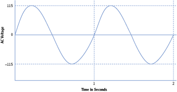
A sine wave cycle is one full 360-degree iteration of the signal. In other words, it starts at zero, goes up, goes back down through zero, and then returns to zero for one cycle.
Figure 7-1: 115 VAC sine wave
A power spike is a short duration increase in voltage. Although it’s quick, it can cause damage to electrical equipment. The most common source of power spikes is a lightning strike. Figure 7-2 shows how spikes may look on an AC sine wave.
Figure 7-2: Power spike on a 115 VAC sine wave
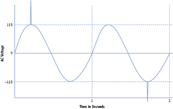
Consider lights in your home. They require 115 VAC, but if there’s an increase or decrease in voltage, you’ll see them flicker. If the voltage increases too high or stays high for too long, they’ll probably burn out. However, lights don’t respond to changes in voltage as quickly as electrical components do. A short spike may not even be noticeable in the light. However, if the same spikes reach electronic components, they will often fail.
Electrical components are protected from power spikes with surge protectors.
Other anomalies with AC voltage include the following:
Power Surge A power surge lasts longer than a power spike and is usually less of an increase in voltage. For example, a power spike from lightening can be thousands of volts for only a few milliseconds. However, a power surge may be only about 20 percent above normal but may last as long as a minute or so.
Power Sag A power sag occurs when the AC voltage falls below normal for a period of time. When a DC power supply doesn’t receive enough AC power, it can’t provide enough DC power to the internal system. Power sags often result in the system turning off.
You can protect computer and networking equipment from power anomalies using different types of equipment:
Surge Protector A surge protector protects against both power spikes and power surges. If excessive voltage reaches the surge protector, a built-in circuit breaker pops and prevents the voltage from reaching the equipment. Most (but not all) power strips include surge protectors. Surge protectors have different rating levels based on their response time and power threshold sensitivity.
Uninterruptible Power Supply (UPS) A UPS provides continuous power to a system even if a power sag occurs or if power is lost for a short period. The primary purpose of a UPS is to provide power to a system by battery long enough to complete a logical shutdown or for generators to come online and stabilize. A UPS is not intended as a long-term power source.
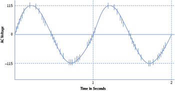
Power Filters Power filters can filter out dirty power. Dirty power occurs when random noise enters the power line and is carried on the sine wave. Instead of a clean sine wave (as shown in Figure 7-1), the signal includes dozens to hundreds of small spikes along the line, as shown in Figure 7-3. This noise can cause damage to power supplies, but a power filter filters out the noise producing a clean sine wave. Power filters also include a surge protector.
Figure 7-3: Dirty power
Generators Generators provide long-term power when the commercial power source fails or is unavailable. Most generators use diesel fuel, though some use natural gas, propane, and even gasoline. Typically, only critical systems require generator power.
Avoiding Interception
Another potential problem with connecting computers on a network is the risk of interception of data as it crosses the network. Just as people can eavesdrop by listening in on conversations, attackers can use tools to eavesdrop on network conversations.
Protocol analyzers can capture traffic going across a network. Although some are hardware devices, most protocol analyzers are simply software programs you can run on any personal computer. They capture the individual packets or frames that cross a network and then allow you to dissect the data. Microsoft provides a free protocol analyzer called Network Monitor.
Protocol analyzers are also called packet analyzers, network analyzers, and sniffers.
Figure 7-4 shows Network Monitor. While this was running and capturing data, I opened a file named Passwords.txt from a network drive named MYBOOKWORLD. Network Monitor captured the entire process including the contents of the opened file.
Figure 7-4: Network Monitor
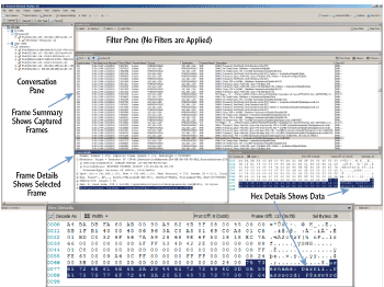
Notice that the contents of the Passwords.txt file (username: Darril..Password: P@ssw0rd) are displayed in readable form in the Hex Details section. (The Hex Details section is shown larger by itself so you can read it easier.)
If someone has this tool, a little bit of knowledge, and some patience, they can intercept data on your network and learn its secrets. Because of this, it’s important to protect your network from interception tactics. Here are some basics:
Use Switches Instead of Hubs Hubs pass all traffic to all ports. A network monitor connected to a hub will capture all traffic going through the hub. In contrast, switches internally switch traffic so that only the traffic that is addressed to a host is sent to the host’s port. In other words, each port is limited in the traffic that it can capture.
Many organizations prohibit the use of hubs in the network to prevent risks of interception.
Protect Network Devices Most routers and switches have maintenance ports that can capture all traffic going to and from the device. If someone has physical access to the devices, they can connect listening devices to these ports and capture all the traffic. Most organizations use physical security to protect network devices such as routers and switches.
Most organizations protect routers and switches in locked wiring closets or server rooms.
Nonpromiscuous Mode vs. Promiscuous Mode
Sniffers run in one of two modes: nonpromiscuous mode or promiscuous mode.
In nonpromiscuous mode, the sniffer will only capture data sent directly to or from the system capturing the traffic. Each frame includes the source and destination IP address, and if the neither of these matches the IP address of capturing computer, the frame isn’t captured. In other words, the sniffer will not capture unicast traffic sent to and from other systems. Microsoft’s Network Monitor runs in this mode by default but can be switched to promiscuous mode.
In promiscuous mode, the sniffer will capture any traffic that reaches the interface card of the system capturing the traffic. Most sniffers can operate in promiscuous mode. Although older free versions of Microsoft’s Network Monitor would not operate in promiscuous mode, the current version can.
Network Monitor comes in three versions, based on the architecture of the system:
- x86 for 32-bit systems
- x64 for 64-bit systems (including both Intel and AMD 64-bit systems)
- ia64 for high-end Itanium servers
You can enter systeminfo at the command prompt to get details on your system. The System Type identifies whether it is x64- or x32-based architecture.
If you try to install the wrong version on a computer, such as installing a 64-bit version on a 32-bit system, the installation program will stop and prompt you to use the correct version.
You can use the following steps to download and install Network Monitor:
These steps were performed on Windows Server 2008 R2 Server but will work similarly on other systems including Windows Server 2008 and Windows 7.
1. Go to Microsoft’s download site (www.microsoft.com/downloads).
2. Type Network Monitor in the Search All Download Center text box, and press Enter.
3. Select Microsoft Network Monitor from the list. At this writing, the current version is 3.4.
4. Identify the version you need (such as the 32-bit version or the 64-bit version), and click the download button for that version.
5. Click Save, and browse to a location on your computer to save it. Once the download is complete, you’re ready to install it.
6. Click Start Computer. Browse to the location where you saved the Network Monitor download, and double-click it.
7. Review the information in the dialog box, and click Yes to continue.
8. Review the information on the Welcome page, and click Next.
9. Review the End-User License Agreement, select I Accept The Terms In The License Agreement, and click Next.
10. If the Microsoft Update page appears, accept the defaults, and click Next.
This page may not appear on some systems if Windows Update has already been configured.
11. Click the Typical button on the Choose Setup Type page. Click Install.
12. After a moment, the installation of Network Monitor will complete. Click Finish. The installation of additional components will then begin and may require several minutes to finish. When it completes, it will automatically close.
After you’ve downloaded and installed Network Monitor, you can use it to capture and review traffic. The following steps assume you have downloaded and installed Network Monitor on a system:
These steps were performed on Windows Server 2008 R2 Server but will work similarly on other systems including Windows Server 2008 and Windows 7.
1. Click Start, and enter Network Monitor in the Search Programs And Files text box.
2. Right-click Microsoft Network Monitor, and select Run As Administrator. If the Microsoft Update Opt-In dialog box appears, choose Yes or No depending on whether you want to check for updates.
3. On the Start Page, locate the Select Networks pane at the bottom left. Ensure your network interface card is selected, as shown in Figure 7-5. If desired, you can select all networks.
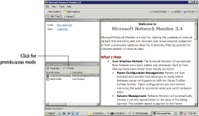
Network Monitor works in nonpromiscuous mode by default. You can configure it to work in promiscuous mode by clicking the P-Mode button in the Select Networks pane.
Figure 7-5: Starting Network Monitor
4. Click New Capture on the toolbar.
5. Click Start page to begin capturing traffic.
6. Open a command prompt, and ping the IP address of one or more systems on your network such as the default gateway or other computers.
You can use ipconfig /all to determine the IP address of your default gateway.
7. When the ping completes, return to Network Monitor, and click Stop.
8. Click All Traffic in the Network Conversations pane. This shows all the traffic that your computer captured during this short time.
9. Click My Traffic. This shows traffic with your computer’s IP address in the Source or Destination column. Enter icmp in the Display Filter pane, and click Apply. Your display will look similar to Figure 7-6. Only ICMP traffic from your pings is shown.
10. Feel free to look around at the different frames that were captured. You can expand any selected frame in the Frame Details pane. When you’re done, close all open windows.

The filter removes all frames except for the frames using the ICMP protocol.
Figure 7-6: Displaying ICMP frames in Network Monitor
Preventing Fire Hazards
Another potential problem with cables is the potential hazardous fumes they can release when they catch on fire. The jacket or covering of some cables can be toxic to humans, so only certain types of cable are safe to use in different areas of a building.
Most buildings have spaces between the walls, below floors, and above ceilings used to circulate cooled or heated air. These spaces are called plenums. And, since it’s such an open space, it’s easy (and common) to run cables through this space. However, if these cables catch fire, the air circulates the fumes from the cables throughout the building.
Cable rated as plenum safe is designed specifically so that it will not release toxic fumes if it catches fire. Only plenum-safe cable should be used within plenums.
Plenum-safe cable is listed as UL 910 or ASTM E84 certified.
Understanding Cross Talk
Cross talk is data that crosses from one transmission line to another. This can result in a degraded signal, or worse, it can result in data jumping from one wire to another.
When data travels down a wire, it creates an induction field that is much larger in diameter than the wire. The induction field is a magnetic field that holds images of the actual signal. Figure 7-7 illustrates this induction field.
Figure 7-7: Induction field around a wire

Tools are available that can capture the signals from the induction field simply by placing the tool around the wire, similar to how you could close your forefinger and thumb around a wire. These tools capture the signals in the magnetic field without cutting into the cable.
Cross talk occurs when signals from one wire cross over to another through these induction fields. As an example, consider Figure 7-8. Cables connecting two classified computers are running side by side with cables connecting two unclassified computers. These signals cross from one wire to the other.
Figure 7-8: Cross talk between two wires
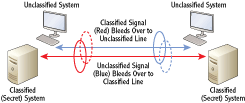
This cross talk results in two problems:
Corruption of Data The cross talk can interfere with intended signals on the wire. This works similar to a collision and requires the retransmission of data.
Loss of Confidentiality If confidential or secret data is transmitted on one wire but crosses to the other wire, the wrong people could pick it up. If unintended recipients learn the secrets, they aren’t secret anymore.
Although shielded twisted pair (STP) provides some resistance against cross talk, it isn’t a guarantee. Most systems that transmit classified data have specific requirements concerning the placement of wires transmitting classified and unclassified data. For example, an organization may specify that classified and unclassified wires can’t be closer than 36 inches to each other.
Exploring Cable Types and Their Characteristics
You connect computers and devices to each other using different types of cables or media. The primary types of media you’ll see in use today are as follows:
Twisted Pair This is a single cable with four pairs of copper wires twisted around each other. Twisted-pair cables are limited to a distance of 100 meters, though you can use repeaters to extend the distance.
Fiber Optic Fiber-optic cable is either glass or a type of plastic that carries light pulses. Fiber-optic cable has a lot of benefits over twisted pair, but it is more expensive. Fiber optic can carry signals distances up to 40 kilometers.
Wireless Wireless networks connect computers together without wires. Instead, devices have transceivers to send and receive radio frequency transmissions. Wireless transmissions are limited to a smaller areas within a building, but multiple wireless access points can be connected together to make the network as large as desired.
When deciding which media to use, you need to be aware of the different characteristics of each. As an example, fiber-optic cable is the most expensive but supports the longest cable runs. Fiber-optic cables can be as long as 40 km. You should be aware of the following primary cable characteristics:
The following sections provide specific details on distance, speed, and frequency for the different media. This section provides a short introduction of these characteristics.
Distance This indicates how long a cable can be between connections, or how far wireless devices can be between each other. All twisted-pair cables are limited to no more than 100 meters. Fiber-optic cable can have much longer cable runs depending on the type of fiber-optic cable used. Wireless is limited to about 30 meters to 90 meters (100 feet to 300 feet) depending on the type of access used.
Speed The speed indicates how much data can travel across the media measured in bits per second (bps). Higher data rate numbers indicate higher speeds and better network performance.
Frequency The frequency refers to the transmission bandwidth. A higher signaling frequency equates to higher speeds on physical media. For wireless media, this indicates the primary frequencies used to transmit the data over the air.
Understanding Twisted Pair
Twisted-pair cable is the most commonly used cable type in networks today. It comes in multiple categories with different speed capabilities. A twisted-pair cable used in a network includes four pairs of copper wire. Each wire in the pair is twisted around each other, and the four pairs within a cable are then twisted around the other pairs. The four twisted pairs are then wrapped in a polyethylene or polyvinyl jacket.
The number of twists per meter in these cables is different for different categories of cables. Twists in the cable help minimize both cross talk and EMI. Additionally, the number of twists per meter determines the speed and frequency capabilities of the cable. Higher speeds and frequencies allow the cable to carry larger amounts of data.
You don’t need to know how many twists per meter a cable has, but you should know the characteristics of different cable categories.
However, all the twisted-pair categories have a maximum distance of 100 meters. In other words, the cable can’t be longer than 100 meters between any two components. It is possible to extend this distance by using a repeater. The repeater amplifies the signal, allowing you to run the cable another 100 meters.
Table 7-1 shows the common twisted pair cable categories you’ll come across in today’s networks along with their basic characteristics.
Category is commonly shortened to CAT. For example, Category 5E cable is Cat 5E.
Table 7-1 Twisted-pair categories

Twisted pair is also identified using the xxBaseT format. The xx indicates the speed. Base indicates that it uses baseband transmissions. Baseband uses a single frequency for transmission, while other methods such as broadband use multiple frequencies. The T indicates it is twisted pair. Some of the common designations are as follows:
10BaseT 10 Mbps twisted pair
100BaseT 100 Mbps twisted pair
1000BaseT 1000 Mbps twisted pair (1 Gbps)
10GBaseT 10 Gbps twisted pair
- The following are the primary problems that twisted pair is susceptible to:
Interference from EMI/RFI Although the twists help prevent EMI and RFI problems, interference can still get in. Shielded twisted pair provides additional protection compared to unshielded twisted pair.
Cross talk Twists also help prevent cross talk problems. Shielded twisted pair provides an additional layer of protection against cross talk. Also, many organizations have rules dictating what type of cables can be run next to each other.
Interception It’s relatively easy for someone to tap the cable and then add connectors to capture the signal. Wire-crimping tools are widely available, and experienced technicians can cut and splice a twisted-pair cable in just a couple of minutes.
Comparing Unshielded and Shielded Twisted Pair
Twisted pair comes in both shielded and unshielded versions. Unshielded twisted pair (UTP) includes the twisted wires encased in a polyethylene or polyvinyl sheath. Shielded twisted pair (STP) includes metal shielding over each pair of wires within the cable. This shielding helps prevent data from escaping beyond the cable from cross talk. It also helps prevent EMI and RFI from entering the cable.
Some UTP cables have foil wrapped around all the pairs and are called foiled twisted pair (FTP) or UTP with screening (S/UTP). This is not the same as STP.
Although the shielding does provide significant protection against EMI/RFI and cross talk, it does not eliminate it. The only way to be immune from these problems is to avoid using copper altogether. Fiber-optic cable is immune to these problems.
Comparing Straight-Through and Crossover Cables
Chapter 2 presented the concept of crossover cables. Straight-through and crossover cables are only used with twisted pair but can be found with both shielded and unshielded cables.
As a reminder, most cables are straight through. The wires going to the pins in a connector in one side of the cable are going to identical pins in the other side of the cable. In other words, pin 1 in one connector is wired to pin 1 in the other connector, pin 2 is wired to pin 2, and so on. Straight-through cables connect dissimilar devices on the network. For example, a computer connected to a hub, switch, or router would use a straight-through cable.
In contrast, crossover cables connect similar devices to each other. For example, you’d use a crossover cable to connect a router with a switch, a wireless access point to a modem, or a computer to another computer.
Gigabit devices use automatic crossover to sense when a crossover connection is needed. Because of this, Cat 6 or 6A crossover cables are rare.
Crossover cables have specific pins in one connector crossed over to different pins in the other connector. Figure 7-9 shows these connections on opposite RJ-45 connectors in a single crossover cable. You can see in the figure the exact pins that specific wires connect to in a EIA/TIA 568B crossover cable.
Figure 7-9: RJ-45 connector views of a crossover cable

Understanding Fiber Optic
Fiber-optic cable sends signals as light pulses rather than as electrical signals. As a result it’s not susceptible to many of the problems associated with twisted pair and can be used for much longer cable runs. There are two primary types of fiber-optic cable: single-mode fiber and multimode fiber.
Single Mode Single-mode fiber (SMF) is smaller than multimode and is used for long-distance high-speed cable runs. A single SMF cable supports 10 Gbps for distances up to 40 km. Single mode uses a glass core.
Multimode Multimode fiber (MMF) uses a plastic core and supports a wider variety of light sources. However, the speed and distance is less than the glass core SMF cable. A single MMF cable supports 100 Mbps for distances up to 2 km and up to 10 Gbps for distances up to 300 m.
Table 7-2 summarizes the characteristics of fiber-optic cable.
Table 7-2 Characteristics of fiber-optic cables
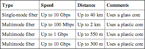
MMF supports higher speeds at shorter distances but can get up to 100 Mbps only if the cable run is 2 km or less.
Compared to the 100 meter runs supported by twisted pair, fiber-optic cable provides significant improvement in the distance of the runs. Fiber also provides several other benefits:
Immune to Interference Fiber is not susceptible to either EMI or RFI since the signals are sent using light pulses. In contrast, twisted pair is susceptible to electromagnetic interference (EMI) and radio frequency interference (RFI).
Immune to Crosstalk Since fiber uses light pulses, it doesn’t generate an induction field around the cable. This eliminates any problems related to cross talk.
Interception Is Difficult Fiber-optic cable is difficult to cut and splice. It requires specialized equipment that isn’t widely available and also requires special skills to ensure the splice works and is not detectable.
Lightweight Fiber cable carries much more data per pound. Individual cables carry more data than twisted pair, and the overall weight is much less. This makes fiber ideal in airplanes and ships where weight and space are both a concern.
The biggest drawback to fiber-optic cable is the cost. The actual cable costs more than twisted pair, and the technicians working on the cable require specialized training to work with the cable.
Fiber-optic cable also has strict limitations on how much it can bend. This can also make a fiber-optic cable installation more expensive.
Understanding Wireless
Just as its name implies, wireless transmission doesn’t use cables. Instead, the transmissions are broadcast over the air on specific frequencies. IEEE 802.11 standards define different wireless characteristics.
Chapter 12 covers wireless networks in much greater depth. This section provides a short introduction and comparison with twisted-pair and fiber-optic cable.
Table 7-3 shows there are four primary wireless standards.
Table 7-3 Characteristics of wireless standards

Wireless transmissions can be degraded by many environmental factors. Actual distances for transmissions vary widely.
Wireless devices provide a simple but valuable benefit. You don’t have to run cables between devices in your network. Instead, you can add a wireless access point (WAP) to your network and use devices with wireless network interfaces. With just a little configuration, you have a running network.
A significant drawback with wireless is that the signals are broadcast over the air and susceptible to interference and interception. When placing the WAPs in a building, you need to ensure that the signal is reachable throughout the building. In a large business, you may place several WAPs to ensure full coverage.
The coverage of the wireless network is referred to as its footprint. The footprint of a wireless network frequently extends outside the intended coverage area.
The frequencies used by wireless networks are well known, and anyone with a wireless receiver can easily capture traffic. Even Microsoft’s Network Monitor can be configured to capture wireless transmissions when it’s run on a computer with a wireless NIC.
Because of this, wireless security is extremely important. Chapter 12 covers the different security protocols you can use to protect wireless transmissions. Older wireless security protocols, such as Wired Equivalent Privacy (WEP), were cracked long ago and provide very little security. Newer wireless security protocols, such as Wi-Fi Protected Access version 2 (WPA2), provide significant security when implemented correctly.
The Essentials and Beyond
In this chapter, you learned about the potential problems of connecting computers on a network and the different types of media used to connect them. Interference comes in the form of EMI and RFI. Power spikes can destroy unprotected systems. Unprotected signals can be intercepted, captured, and analyzed using tools such as Microsoft’s Network Monitor. Twisted pair is the most popular media, though it is susceptible to EMI/RFI, interception, and cross talk. Fiber optic is immune to interference and cross talk problems, and it is much more difficult to tap into to intercept the signals. Wireless is very easy to set up and configure, though it requires additional steps to protect the data transmission.
Additional Exercises
- Identify the power source of the computer you’re using. Determine whether it is a surge protector.
- Download Network Monitor from the Internet and install it if you haven’t already. Capture some traffic on your network. Filter the traffic so that only TCP traffic is displayed.
- Locate the switch or router that your computer is connected to. Determine whether it is protected with physical security.
- Look at the cable used in your network. Determine whether it is plenum safe.
- To compare your answers to the author’s, please visit www.sybex.com/go/networkingessentials.
Review Questions
1. What types of interference can cause problems for networks? (Choose all that apply.)
|
A. EMI |
C. STI |
|
B. RFI |
D. PCI |
2. A short-duration increase in AC power is a _____________.
|
A. power spike |
C. power sag |
|
B. power surge |
D. surge protector |
3. True or false. The purpose of a UPS system is to provide long-term power when power fails.
4. True or false. STP provides protection against interference and cross talk.
5. The maximum distance of a CAT 6 twisted-pair cable between two connections is _____________ meters.
6. What is the speed of a CAT 6 cable?
|
A. 10 Mbps |
C. 1000 Mbps |
|
B. 100 Mbps |
D. 10000 Mpbs |
7. What does the T represent in a 100BaseT cable?
8. What tool can you use to capture traffic going across a network? (Choose all that apply.)
|
A. Microsoft’s Network Monitor |
C. A network sniffer |
|
B. A protocol analyzer |
D. A wire crimper |
9. What frequency does 802.11g use?
|
A. 2.4 GHz |
C. 2.4 and 5 GHz |
|
B. 5 GHz |
D. 9 GHz |
