Office Communications Server 2007 differs most significantly from earlier versions in the change from a monolithic server architecture to one with distributed server components. In addition, Office Communications Server 2007 introduces two new scenarios—conferencing and VoIP—and, as a result, new server roles. This chapter provides an architecture overview as well as an overview of the internal components that make up Office Communications Server.
Office Communications Server 2007 extends the architecture of Live Communications Server 2005 to include components that support VoIP and conferencing. This section discusses the following architectural features:
Pool configurations
Front-end servers
Conferencing components
VoIP components
Perimeter network configuration and components
Conference protocols
Conference call flow
Figure 19-1 illustrates a generic Office Communications Server topology, including the new Voice over Internet Protocol (VoIP) and conferencing components.

The remainder of this section discusses the various servers in this topology and the functionality that each provides.
An Office Communications Server 2007 pool consists of one or more front-end servers that provide instant messaging (IM), presence, and conferencing services and are connected to a SQL Server database for storing user information, such as a user's configuration data, presence status, and conferencing details. Depending on the pool configuration, the database might reside on the same physical machine. In addition, certain conferencing components might be deployed on the same physical computer, depending on the chosen pool configuration.
Office Communications Server 2007 offers three pool configurations: one Standard Edition configuration, and the consolidated and expanded Enterprise Edition configurations. Both Enterprise Edition configurations consist of identical front-end servers that are connected to a separate dedicated Microsoft SQL Server 2005 back-end database. (In an Enterprise pool, the back-end database must be on a dedicated computer, separate from all Enterprise Edition servers.)
As shown in Figure 19-2, a Standard Edition server hosts all necessary services on a single front-end server. Because it requires a minimal hardware investment and minimal management overhead, the Standard Edition configuration is ideal for small and medium-sized businesses and for branch offices. It is intended for deployments with fewer than 5000 users either in total or at a particular location where high availability is not a requirement.

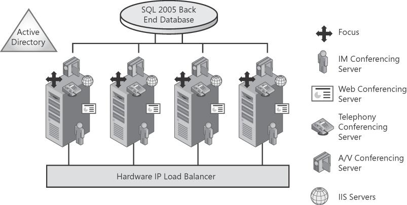
As shown in Figure 19-3, the Enterprise Edition consolidated configuration is a pool configuration in which all server components are collocated on the pool's front-end servers (with the exception of the back-end database, which must reside on a separate dedicated computer). The consolidated configuration provides scalability and high availability and yet is easy to plan, deploy, and manage.
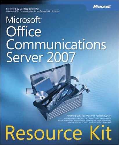
The Enterprise Edition expanded configuration offers maximum capacity, performance, and availability for large organizations. As shown in Figure 19-4, Expanded Configuration, Internet Information Services (IIS), the Web Conferencing Server, and the Audio/Video Conferencing Server are installed on dedicated computers separate from the pool's front-end servers. Expanded configuration enables organizations to scale up audio/video or Web conferencing requirements independently from other Enterprise Edition server components. For example, if an organization's audio/video traffic increases more rapidly than other traffic, the organization can meet this increase by deploying only additional Audio/Video Conferencing Servers rather than entire front-end servers.
As Figure 19-4 shows, the IM Conferencing Server and Telephony Conferencing Server are located on the front-end server, even in the expanded configuration, whereas the Web Conferencing Server, A/V Conferencing Server, and IIS are installed on separate, dedicated computers. In the figure, the front-end servers are connected to one hardware load balancer and the servers running IIS (Web Components Servers) are connected to a separate load balancer. You can, however, also use the same hardware load balancer for both the Web Components Servers and the front-end servers.
The Office Communications Server 2007, Standard Edition or Enterprise Edition, front-end server is responsible for the following tasks:
Handling signaling among servers and between servers and clients
Authenticating users and maintaining user data, including all user endpoints
Routing VoIP calls within the enterprise and to the Public Switched Telephone Network (PSTN)
Initiating on-premise conferences and managing conference state
Providing enhanced presence information to clients
Managing conferencing media
Hosting applications
Filtering SPIM (unsolicited commercial IM traffic)
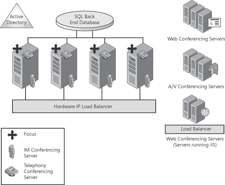
Conceptually, a pool consists of one or more front-end servers and one or more databases on the back-end database server with a single SQL Server. All persistent state is stored in the database on the back-end database server so that, when a front-end server component fails, failover can be quick.
The Focus stores all conference state in the back-end database server to ensure it is accessible to all front-end servers. With this model, if a client loses connectivity to the conferencing server, the client can reconnect and its request can be handled by any of the front-end servers. This provides a natural failover model for front-end failures as well as for temporary loss of network connectivity from client to server. Similarly, information about conferencing server load also persists on the back-end database server so that it is available to a Conferencing Server Factory instance on any front-end server. This data can be written by a Conferencing Server Factory to the database, but any conferencing server for a particular media type under the control of the Conferencing Server Factory can read the database.
Figure 19-5 shows a sample pool with two front-end servers and one back-end database server. There is an IP load balancer for the front-end servers. All conferencing elements—Focus, Focus Factory, Conferencing Server Factory, A/V Conferencing Server, and Web Conferencing Server—are installed on all the front-end servers.
Note
More details on conferencing can be found in Chapter 5.
The remainder of this chapter focuses on the components that make up Office Communications Server, such as the sip stack, User Services module, Session Initiation Protocol (SIP) application programming interface (API), and archiving.