
Chapter 7
Ensuring High Availability and Business Continuity
Ensuring high availability and business continuity is a key part of virtualization that is often overlooked or considered after the fact. It is equally as important as configuring storage devices and setting up virtual networking. Virtualization and VMware vSphere in particular enable new ways to provide high availability and business continuity. There are multiple layers where vSphere administrators can help provide high availability in a variety of ways depending on the needs of the business and the unique requirements of the organization. This chapter discusses some of the tools and techniques available for ensuring high availability and business continuity.
In this chapter, you will learn to
- Understand Windows clustering and the different types of clusters
- Use vSphere's built-in high-availability functionality
- Recognize differences between different high-availability solutions
- Understand additional components of business continuity
Understanding the Layers of High Availability
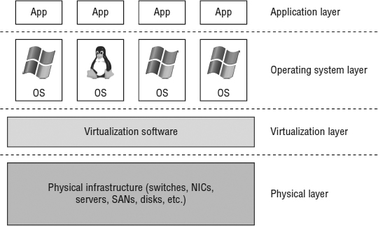
Even in nonvirtualized environments, there are multiple ways to achieve high availability for OS instances and applications. When you introduce virtualization into the mix with vSphere, you gain additional methods of providing high availability. Figure 7.1 shows these different layers.
FIGURE 7.1 Each layer has its own forms of high availability.
At each layer, there are tools and techniques for providing high availability and business continuity:
- At the Application layer, options include Oracle Real Application Clusters (RAC).
- At the OS layer, solutions include OS clustering functionality, such as Windows Server Failover Clustering (WSFC).
- The Virtualization layer offers a number of features for high availability, including vSphere High Availability (HA) and vSphere Fault Tolerance (FT).
- At the Physical layer high availability is achieved through redundant hardware—multiple network interface cards (NICs) or host bus adapters (HBAs), multiple storage area network (SAN) switches and fabrics, multiple paths to storage, multiple controllers in storage arrays, redundant power supplies, and so forth.
Each of these various technologies or techniques has its own strengths and weaknesses. For example, providing redundancy at the Physical layer is great, but it doesn't help with failures at the Application layer. Conversely, protecting against application failures is great but won't help much if the underlying hardware isn't redundant. As you set forth to establish high availability for your virtualized workloads, keep in mind that there is no “one size fits all” solution. Use the right tool for the job based on your specific requirements.
Given that this is a book on vSphere, we can cover only some of the various possibilities for ensuring high availability, so we'll focus out efforts on three key technologies or techniques that help provide high availability:
- OS clustering in Microsoft Windows
- ESXi host clustering using vSphere HA
- VM mirroring using vSphere FT
After a discussion of these three broad areas, we discuss some areas relating to business continuity. You can find details relating to High Availability at the physical layer in other chapters of this book, such as Chapter 5, “Creating and Configuring Virtual Networks,” and Chapter 6, “Creating and Configuring Storage Devices.”
First, though, let's start with a well-known technique for achieving high availability at the OS level: OS clustering, specifically clustering Microsoft Windows Server instances.
Clustering VMs
Because Windows Server is widely used in corporate and enterprise datacenters today, it's quite likely that at one point or another you've been asked to create or support a Windows-based cluster. There are two primary ways to use clustering to provide high availability for Windows Server:
- Network Load Balancing (NLB) clustering
- Windows Server Failover Clustering (WSFC)
While both of these methods are described as clustering, they each target very different purposes. NLB typically provides scalable performance, while WSFC usually focuses on providing redundancy and high availability in the form of active/passive workload clustering.
Some experts say that vSphere HA eliminates the need for WSFC because—as you'll see late in this chapter in the section “Implementing vSphere High Availability”—vSphere HA can provide failover in the event of a physical host failure. That's true, but it's important to understand that these high-availability mechanisms operate at different layers (refer back to Figure 7.1). WSFC operates at the OS layer, providing redundancy in the event that one of the OS instances in the cluster fails. That OS failure could be the result of hardware failure. vSphere HA (and vSphere FT) operate at a layer beneath the OS and don't operate in exactly the same way. As we'll reiterate throughout this chapter, each of the high-availability mechanisms described in this chapter has advantages and disadvantages. You'll want to be sure you understand these so that you can choose the right approach for your specific environment.
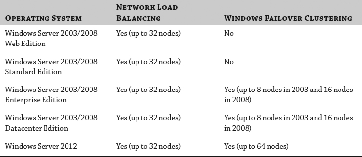
Table 7.1 provides a quick overview of the clustering support provided by the various versions of Windows Server.
TABLE 7.1: Windows Server 2003/2008 clustering support
We'll start with a quick review of NLB clustering and how you can use it in your vSphere environment.
Introducing Network Load Balancing Clustering
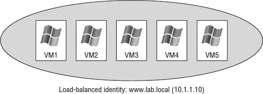
The Network Load Balancing configuration involves an aggregation of stateless servers that balances the requests for applications or services. In a typical NLB cluster, all nodes are active participants in the cluster and are consistently responding to requests for services. If one of the nodes in the NLB cluster goes down, client connections are simply redirected to another available node in the NLB cluster. NLB clusters are most commonly deployed to enhance performance and availability. Because client connections could be directed to any available node within the cluster, NLB clusters are best suited for scenarios involving stateless connections and protocols, such as environments using Microsoft Internet Information Services (IIS), virtual private networking (VPN), or Microsoft Internet Security and Acceleration (ISA) Server, to name a few. Figure 7.2 summarizes the architecture of an NLB cluster made up of Windows-based VMs (the architecture is the same for physical systems).
FIGURE 7.2 An NLB cluster can contain up to 32 active nodes (only 5 are shown here), and traffic is distributed equally across each available node. The NLB software allows the nodes to share a common name and IP address that is referenced by clients.
NETWORK LOAD-BALANCING SUPPORT FROM VMWARE
As of this writing, VMware supports NLB, but you will need to run NLB in Multicast mode to support vMotion and VMs on different physical hosts. You will also need to configure static Address Resolution Protocol (ARP) entries on the physical switch to achieve this, which greatly limits the scalability of the solution. If NLB is running in Unicast mode, then the VMs will all need to be running on the same host, which is generally not a good idea if you want high availability! Another option to consider would be third-party load balancers to achieve the same results.
NLB clusters aren't the right fit for every application or workload. For applications and workloads that aren't a good fit for NLB, Microsoft offers Windows Server Failover Clustering.
Introducing Windows Server Failover Clustering
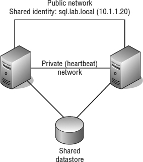
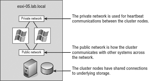
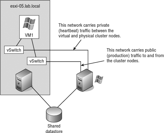
Unlike NLB clusters, Windows Server Failover Clustering (WSFC) clusters (which we'll refer to as server clusters, failover clusters, or simply WSFC from here on) are used solely for the sake of availability. Server clusters do not enhance performance outside of high availability. In a typical server cluster, multiple stateful nodes are configured to be able to own a service or application resource, but only one node owns the resource at a given time. Server clusters are most often used for applications like Microsoft SQL Server and DHCP services, in which each share the need for a common datastore. The common datastore houses the information accessible by the node that is online and currently owns the resource as well as the other possible owners that could assume ownership in the event of failure. Each node requires at least two network connections: one for the production network and one for the cluster service heartbeat between nodes. Figure 7.3 details the structure of a server cluster built using physical systems (we'll illustrate several ways server clusters are built with VMs later in the next section, “Reviewing VM Clustering Configurations”).
FIGURE 7.3 Server clusters are best suited for applications and services like SQL Server, DHCP, and so on, which use a common dataset.
Server clusters, when constructed properly, provide automatic failover of services and applications hosted across multiple cluster nodes. When multiple nodes are configured as a cluster for a service or application resource, only one node owns the resource at any given time. When the current resource owner experiences failure, causing a loss in the heartbeat between the cluster nodes, another node assumes ownership of the resource to allow continued access with minimal data loss. Windows Server has multiple ways of configuring Windows Server Failover Clustering, or Microsoft Cluster Server (MSCS). Because this is a VMware book and not a Windows Server book, we'll concentrate examples on the most popular Windows Server version, 2008 R2. To configure multiple Windows Server 2008 nodes into a Microsoft cluster, the following requirements must be met:
- Nodes must be running either Enterprise Edition or Datacenter Edition of Windows Server 2008.
- All nodes should have access to the same storage device(s). The specific details of the storage device(s) and how they are shared will depend on how the cluster is built.
- All nodes should have two similarly connected and configured network adapters: one for the production (or public) network and one for the heartbeat (or private) network.
- All nodes should have Microsoft Cluster Services for the version of Windows that you are using.
Earlier versions of Microsoft Exchange used to align to the shared storage based on the cluster model that we've just explained. However, Exchange 2010 introduced a new concept, the database availability groups (DAGs). While Exchange can still be installed with an application-based cluster configuration, it has departed from the common requirement of shared storage and uses local storage on each node instead. Because of the I/O profile that Exchange can require, local storage is seen to be a better fit for this application. Before we can provide you with the details on how to build a server cluster running Microsoft Windows Server 2008 on vSphere, we first need to discuss the different scenarios of how server clusters can be built.
REVIEWING VM CLUSTERING CONFIGURATIONS
Building a server cluster with Windows Server 2008 VMs requires one of three different configurations, as follows:
Cluster in a Box The clustering of VMs on the same ESXi host is also known as a cluster in a box. This is the easiest of the three configurations to set up. Minimal configuration needs to be applied to make this work.
Cluster across Boxes The clustering of VMs that are running on different ESXi hosts is known as a cluster across boxes. VMware had restrictions in place for this configuration in earlier versions: the cluster node's C: drive must be stored on the host's local storage or local VMFS datastore, the cluster shared storage must be stored on Fibre Channel external disks, and you must use raw device mappings on the storage. In vSphere 4 and vSphere 5, this was changed and updated to allow .vmdk files on the SAN and to allow the cluster VM boot drive or C: drive on the SAN, but vMotion and vSphere Distributed Resource Scheduler (DRS) are not supported using Microsoft-clustered VMs.
Physical-to-Virtual Clustering The clustering of a physical server and a VM together is often referred to as a physical-to-virtual cluster. This configuration of using physical and virtual servers together gives you the best of both worlds, and the only other added restriction is that you cannot use Virtual Compatibility mode with the RDMs.
We'll examine all three configurations in more details in the sections that follow.
Building Windows-based server clusters has long been considered an advanced technology practiced only by those with high technical skills in implementing and managing high-availability environments. Although this might be more rumor than truth, it is certainly a more complex solution to set up and maintain, and running on top of a hypervisor can increase this complexity.
Although you might succeed in setting up clustered VMs, you may not receive support for your clustered solution if you violate any of the clustering restrictions put forth by VMware. The following list summarizes and reviews the dos and don'ts of clustering VMs as published by VMware:
- 32-bit and 64-bit VMs can be configured as nodes in a server cluster.
- Majority node set clusters with application-level replication (for example, Microsoft Exchange 2007 cluster continuous replication) are now supported.
- Up to five-node clustering is allowed.
- Clustering does not support NIC teaming in the VMs.
- VMs configured as cluster nodes must use the LSI Logic SCSI adapter (for Windows Server 2003) or the LSI Logic SAS adapter (for Windows Server 2008) and the vmxnet network adapter.
- VMs in a clustered configuration are not valid candidates for vSphere FT or Storage DRS. They can be part of a cluster that has these features enabled, but the features must be disabled for the VMs participating in the server cluster.
- VMs in a server cluster cannot use N_Port ID Virtualization.
- All the ESXi systems hosting VMs that are part of a server cluster must be running the same version of ESXi.
There is something else that you need to do. You must set the I/O timeout to 60 seconds or more by modifying HKLMSystemCurrentControlSetServicesDiskTimeOutValue, and if you re-create a cluster, you'll need to reset the value again. Additionally, it's a good idea to check this value on each node when VMware Tools is installed or upgraded.
So, let's get into some more details on clustering and look at the specific clustering options available in the virtual environment. We will start with the most basic design configuration, the cluster in a box.
EXAMINING CLUSTER-IN-A-BOX SCENARIOS
The cluster-in-a-box scenario involves configuring two VMs hosted by the same ESXi host as nodes in a server cluster. The shared disks of the server cluster can exist as .vmdk files stored on local Virtual Machine File System (VMFS) volumes or on a shared VMFS volume. Figure 7.4 details the configuration of a cluster in a box.
FIGURE 7.4 A cluster-in-a-box configuration does not provide protection against a single point of failure. Therefore, it is not a common or suggested form of deploying Microsoft server clusters in VMs.
After reviewing the diagram of a cluster-in-a-box configuration, you might wonder why you would want to deploy such a thing. The truth is, you would want to deploy a cluster-in-a-box configuration only in certain circumstances because it still maintains a single point of failure. With both VMs running on the same host, if that host fails, both VMs fail. This architecture contradicts the very reason for creating failover clusters. A cluster-in-a-box configuration still contains a single point of failure that can result in downtime of the clustered application. If the ESXi host hosting the two-node cluster-in-a-box configuration fails, then both nodes are lost, and a failover does not occur. It's a relatively simple setup to configure and probably best suited for learning or testing the cluster service configurations. You may also find yourself in a situation where it's needed for planned downtime or patching.
CONFIGURATION OPTIONS FOR VIRTUAL CLUSTERING
As suggested in the first part of this chapter, server clusters are deployed for high availability. In a vSphere-based outage, high availability is not achieved by using a cluster-in-a-box configuration, and therefore you should avoid this configuration for any type of critical production applications and services.
EXAMINING CLUSTER-ACROSS-BOXES CONFIGURATIONS
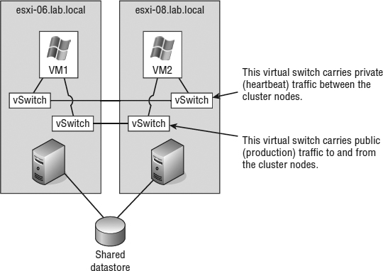
Although the cluster-in-a-box scenario is more of an experimental or education tool for clustering, the cluster-across-boxes configuration provides a solid solution for critical VMs with stringent uptime requirements—for example, the enterprise-level servers and services like SQL Server and Exchange Server that are heavily relied upon by the bulk of end users. The cluster-across-boxes scenario, as the name applies, draws its high availability from the fact that the two nodes in the cluster are managed on different ESXi hosts. In the event that one of the hosts fails, the second node of the cluster will assume ownership of the cluster group and its resources, and the service or application will continue responding to client requests.
The cluster-across-boxes configuration requires that VMs have access to the same shared storage, which must reside on a Fibre Channel, FCoE, or iSCSI storage device external to the ESXi hosts where the VMs run. The virtual hard drives that make up the operating system volume of the cluster nodes can be a standard VMDK implementation; however, the drives used as the shared storage must be set up as a special kind of drive called a raw device mapping (RDM). An RDM is a feature that allows a VM to establish direct access to a LUN on a SAN device. We also discussed RDMs briefly in Chapter 6.
A cluster-across-boxes configuration requires a more complex setup than a cluster-in-a-box configuration. When clustering across boxes, all proper communication between VMs and all proper communication from VMs and storage devices must be configured properly. Figure 7.5 provides details on the setup of a two-node VM cluster-across-box configuration using Windows Server 2008 as the guest operating system (guest OS).
FIGURE 7.5 A Microsoft cluster built on VMs residing on separate ESXi hosts requires shared storage access from each VM using an RDM.
USING RAW DEVICE MAPPINGS IN YOUR VIRTUAL CLUSTERS
An RDM is not a direct access to a LUN, and it is not a normal virtual hard disk file. An RDM is a blend of the two. When you're adding a new disk to a VM, as you will soon see, the Add Hardware Wizard presents the RDMs as an option on the Select A Disk page. This page defines the RDM as having the ability to give a VM direct access to the SAN, thereby allowing SAN management. We know this seems like a contradiction to the opening statement of this sidebar; however, we're getting to the part that, oddly enough, makes both statements true.
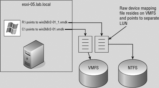
By selecting an RDM for a new disk, you're forced to select a compatibility mode for the RDM. An RDM can be configured in either Physical Compatibility mode or Virtual Compatibility mode. The Physical Compatibility mode option allows the VM to have direct raw LUN access. The Virtual Compatibility mode, however, is the hybrid configuration that allows raw LUN access but only through a VMDK file acting as a proxy. The following image details the architecture of using an RDM in Virtual Compatibility mode.
So, why choose one over the other if both are ultimately providing raw LUN access? Because the RDM in the Virtual Compatibility mode file offers the advantage of allowing snapshots to be taken. By using the Virtual Compatibility mode, you will gain the ability to use snapshots on top of the raw LUN access in addition to any SAN-level snapshot or mirroring software. Or, of course, in the absence of SAN-level software, the VMware snapshot feature can certainly be a valuable tool. The decision to use Physical Compatibility or Virtual Compatibility is predicated solely on the opportunity and/or need to use VMware snapshot technology or when using physical-to-virtual clustering.
Make sure you document things well when you start using RDMs. Any storage that is presented to ESXi, is not formatted with VMFS, and has not already been allocated as an RDM will show up as available storage. If all the administrators are not on the same page, it used to be very easy to take a LUN that was used for an RDM and reprovision that LUN as a VMFS datastore, effectively blowing away the RDM data in the process. RDMs are now hidden by default when they are allocated, but we have seen this mistake happen firsthand, and let us tell you, the process is very quick to erase any data that is there. We have gone so far as to create a separate column in vCenter Server to list any RDM LUNs that are configured to make sure everyone has a reference point; similarly you might want to use a tag (explained in Chapter 3, “Installing and Configuring vCenter Server”).
Let's keep moving and perform the following steps to configure Microsoft Cluster Services on Windows Server 2008 across VMs on separate ESXi hosts.
Creating the First Cluster Node in Windows Server 2008
Perform the following steps to create the first cluster node:
- Using the vSphere Web Client, create a new VM, and install Windows Server 2008 (or clone an existing VM or template with Windows Server 2008 already installed).
Refer to Chapter 9, “Creating and Managing Virtual Machines,” for more details on creating VMs; refer to Chapter 10, “Using Templates and vApps,” for more information on cloning VMs.
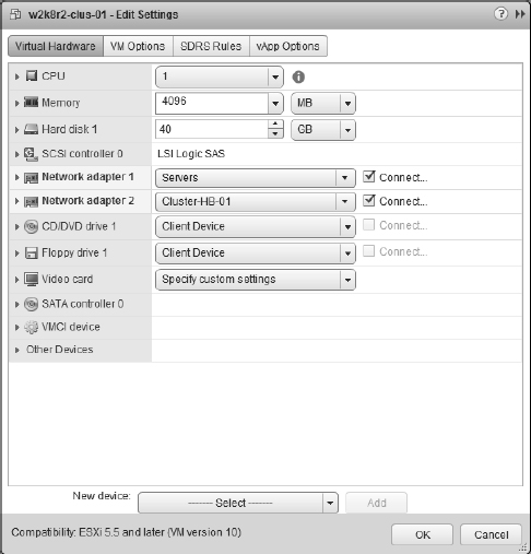
- Configure the VM so that it has two NICs, as shown in Figure 7.6—one for the public (production) network and one for the private (heartbeat) network. Assign IP addresses within Windows Server 2008 as needed. Shut down the VM after you have completed the networking configuration.
- Right-click the new VM and select Edit Settings.
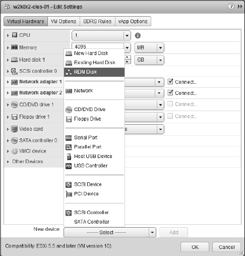
- Click the New Device drop-down, select RDM Disk and click Add, as shown in Figure 7.7.
- Select the appropriate target LUN from the list of available targets, and then click OK.
We'll remind you again: Make sure you have the correct LUN or you could overwrite important data!
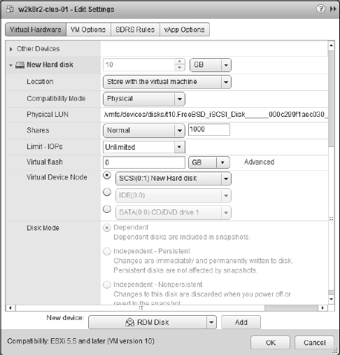
- Click the arrow next the New Hard Disk item and next to Location choose “Store with the virtual machine to keep the VMDK proxy file on the same datastore as the VM.”
- Select either Physical or Virtual for the RDM compatibility mode.
FIGURE 7.6 A node in a Microsoft Windows Server cluster requires at least two NICs. One adapter must be able to communicate on the production network, and the second adapter is configured for internal cluster heartbeat communication.
FIGURE 7.7 Add a new device of type RDM Disk for the first node in a cluster and Existing Hard Disk for additional nodes.
Different versions have different requirements. In this case, select Physical and then click Next.
RDM REQUIREMENTS FOR WINDOWS SERVER 2003 AND WINDOWS SERVER 2008
When building a cluster across multiple ESXi hosts using Windows Server 2003, you can use Virtual mode RDMs. If you are using Windows Server 2008 to build the cluster across ESXi hosts, you must use Physical Compatibility mode.
- Select the virtual device node to which the RDM should be connected, as shown in Figure 7.8.
Note that you must select a different SCSI node; you can't put the RDM on SCSI 0.0.
SCSI NODES FOR RDMs
RDMs used for shared storage in a Microsoft server cluster must be configured on a SCSI node that is different from the SCSI to which the hard disk is connected and that holds the operating system. For example, if the operating system's virtual hard drive is configured to use the SCSI0 node, then the RDM should use the SCSI1 node. This rule applies to both virtual and physical clustering.
FIGURE 7.8 The SCSI bus sharing for the new SCSI adapter must be set to Physical to support running a Microsoft cluster across multiple ESXi hosts.
- Repeat steps 2 through 8 to configure additional RDMs for shared storage locations needed by nodes of a Microsoft server cluster.
In this case, we're going to present a single RDM.
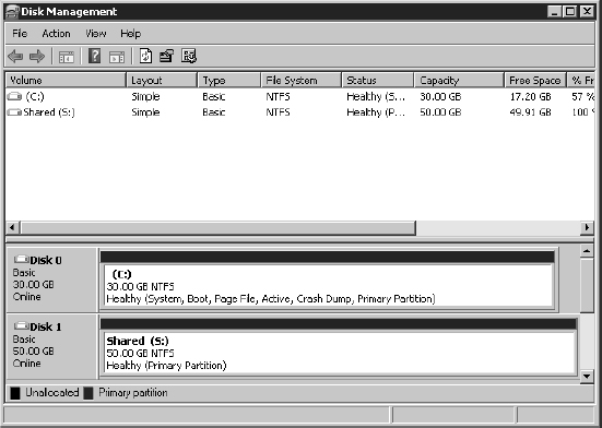
- Power on the first node of the cluster. Verify that you've assigned valid IP addresses to the network adapters configured for the production and heartbeat networks. Then format the new drive representing the RDM and assign drive letters, as shown in Figure 7.9.
FIGURE 7.9 The RDM presented to the first cluster node is formatted and assigned a drive letter.
- Proceed to the next section to configure the second cluster node and the respective ESXi host.
Creating the Second Cluster Node in Windows Server 2008
Perform the following steps to create the second cluster node:
- Using the vSphere Web Client, create a second VM running Windows Server 2008 that is a member of the same Active Directory domain as the first cluster node. Ensure that the VM has two NICs and that the NICs have appropriate IP addresses assigned for the production (public) and heartbeat (private) networks.
- Shut down the second VM.
- Add the same RDMs to the second cluster node.
This time around, you can't select Raw Device Mappings, because the LUN you selected when setting up the first node won't be listed (it's already been used). Instead, select Existing Virtual Disk, as shown in Figure 7.7, and then navigate to the location of the VMDK proxy file (if you selected Store With The Virtual Machine in step 6 of setting up the first node, you'll find a VMDK file there with the same size as the backing LUN).
Be sure to use the same SCSI node values on the second VM. For example, if the first node used SCSI 1:0 for the first RDM, then configure the second node to use the same configuration. Don't forget to edit the SCSI bus sharing configuration for the new SCSI adapter (Physical SCSI bus sharing).
- Power on the second VM.
- Verify that the hard drives corresponding to the RDMs can be seen in Disk Manager. At this point, the drives will show a status of Healthy, but drive letters will not be assigned.
Creating the Failover Cluster in Windows Server 2008
Perform the following steps to create the management cluster:
- Log into the first node as an administrative user.
- Launch Server Manager from the Start menu, if it doesn't launch automatically.
- Click Add Features.
- From the list of features in the Add Features Wizard, select Failover Clustering and click Next.
- Click Install. When the install is completed, click Close.
- Repeat this process on the second node.
With failover clustering installed on both nodes, you can validate the cluster configuration to ensure that everything is configured properly:
- Log into the first node as an administrative user.
- From the Start menu, select Administrative Tools
 Failover Cluster Management.
 - Click Validate A Configuration. This launches the Validate A Configuration Wizard. Click Next to start the wizard.
- Enter the names of both the first and second cluster nodes, clicking Add after each server name to add it to the list. Click Next.
- Leave the default selection (Run All Tests) and click Next.
- Click Next at the Confirmation step.
- Review the report. If any errors are reported, follow the guidance to address the errors. Click Finish when you are done.
Now you're ready to create the cluster:
- While still logged into the first node as an administrative user and still running Failover Cluster Management, click Create A Cluster.
- At the first screen of the Create Cluster Wizard, click Next.
- Enter the names of both nodes, and click Add after each server to add it to the list. Click Next to continue.
- Select the option to not run the validation tests (you've already run them). Click Next.
- Specify a cluster name and an IP address on the production (public) network. Click Next to continue.
- Click Next at the Confirmation screen.
- The Create Cluster Wizard will perform the necessary steps to create the cluster and bring the resources online. When it has completed, review the report and click Finish.
After the cluster is up and running, you can use the Failover Cluster Management application to add resources, applications, and services. Some applications, such as Microsoft SQL Server and Microsoft Exchange Server, not only are cluster-aware applications but also allow you to create a server cluster as part of the standard installation wizard. Other cluster-aware applications and services can be configured into a cluster using the cluster administrator. Refer to the documentation for Microsoft Windows Server 2008 and/or the specific application you want to cluster for more details.
EXAMINING PHYSICAL-TO-VIRTUAL CLUSTERING
The last type of clustering scenario to discuss is physical-to-virtual clustering. As you might have guessed, this involves building a cluster with two nodes where one node is a physical machine and the other node is a VM. Figure 7.10 details the setup of a two-node physical-to-virtual cluster.
FIGURE 7.10 Clustering physical machines with VM counterparts can be a cost-effective way of providing high availability.
The constraints surrounding the construction of a physical-to-virtual cluster are identical to those noted in the previous configuration. Likewise, the steps to configure the VM acting as a node in the physical-to-virtual cluster are identical to the steps outlined in the previous section, with one addition: You must set up the RDMs in Physical Compatibility mode, regardless of the version of Windows Server you're using. The VM must have access to all the same storage locations as the physical machine. The VM must also have access to the same pair of networks used by the physical machine for production and heartbeat communication, respectively.
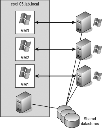
The advantage to implementing a physical-to-virtual cluster is the resulting high availability with lower cost. Physical-to-virtual clustering, because of the two-node limitation of VM clustering, ends up as an N+1 clustered solution, where N is the number of physical servers in the environment and the 1 represents one additional physical server to host the VMs. In each case, each physical VM cluster creates a failover pair. With the scope of the cluster design limited to a failover pair, the most important design aspect in a physical-to-virtual cluster is the scale of the host running the ESXi host. As you may have figured, the more powerful the ESXi host, the more failover incidents it can handle. A more powerful ESXi host will handle multiple physical host failures better, whereas a less powerful ESXi host might handle only a single physical host failure before performance levels experience a noticeable decline. Figure 7.11 shows an example of many-to-one physical-to-virtual clustering.
FIGURE 7.11 Using a single powerful ESXi system to host multiple failover clusters is one use case for physical-to-virtual clustering.
OS CLUSTERING IS NOT LIMITED TO WINDOWS
Although we've discussed only Windows Server–based OS clustering methods in this section, you are not limited to Windows to use OS clustering. Other supported OSes also offer ways to provide high availability within the OS itself.
Now that we've covered OS clustering in Windows Server, let's take a look at VMware's version of high availability. VMware has a built-in option called vSphere High Availability (HA). As you'll see, vSphere HA uses a very different method than OS clustering to provide high availability.
Implementing vSphere High Availability
You've already seen how you can use OS clustering to provide high availability for OSes and applications. In addition to OS clustering, vSphere provides a feature intended to provide high availability at the virtualization layer. vSphere High Availability (HA) is a component of the vSphere product that provides for the automatic failover of VMs. Because the term high availability can mean different things to different people, it's important to understand the behavior of vSphere HA to ensure that you are using the right high-availability mechanism to meet the requirements of your organization. Depending on your requirements, one of the other high-availability mechanisms described in this chapter might be more appropriate.
A COMPLETE REWRITE FROM PREVIOUS VERSIONS
The underpinnings of vSphere HA underwent a complete rewrite for vSphere 5.0. If you are familiar with older versions of vSphere, keep this in mind as you look at how vSphere HA behaves in this version.
Understanding vSphere High Availability
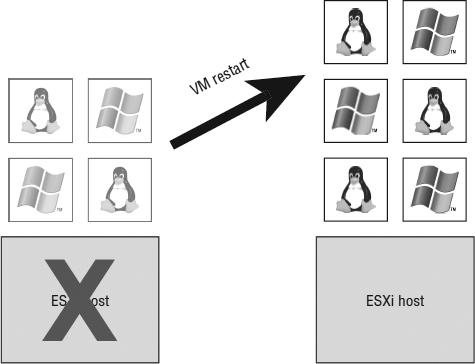
The vSphere HA feature is designed to provide an automatic restart of the VMs that were running on an ESXi host at the time it became unavailable, as shown in Figure 7.12.
FIGURE 7.12 vSphere HA provides an automatic restart of VMs that were running on an ESXi host when it failed.
vSphere HA primarily targets ESXi host failures, but it can also be used to protect against VM- and application-level failures. In all cases, vSphere HA uses a restart of the VM as the mechanism for addressing the detected failure. This means there is a period of downtime when a failure occurs. Unfortunately, you can't calculate the exact duration of the downtime because it is unknown ahead of time how long it will take to boot a VM or a series of VMs. From this you can gather that vSphere HA might not provide the same level of high availability found in other high-availability solutions. Further, when a failover occurs between ESXi hosts as a result of the vSphere HA feature, there is a slight potential for data loss and/or filesystem corruption because the VM was immediately powered off when the server failed and then brought back up minutes later on another server. However, given the journaling filesystems in use by Windows and many distributions of Linux, this possibility is relatively slim.
![]() Real World Scenario
Real World Scenario
VSPHERE HA EXPERIENCE IN THE FIELD
Author Nick Marshall says, “I want to mention my own personal experience with vSphere HA and the results I encountered. Your mileage might vary, but this should give you a reasonable expectation of what to expect. I had a VMware ESXi host that was a member of a five-node cluster. This node crashed some time during the night, and when the host went down, it took anywhere from 15 to 20 VMs with it. vSphere HA kicked in and restarted all the VMs as expected.
“What made this an interesting experience is that the crash must have happened right after the polling of the monitoring and alerting server. All the VMs that were on the general alerting schedule were restarted without triggering any alerts. Some of the VMs with more aggressive monitoring that tripped off alerts that were recovered before anyone was able to log into the system and investigate. I tried to argue the point that if an alert never fired, did the downtime really happen? I did not get too far with that argument, but I was pleased with the results.
“In another case, during testing I had a VM running on a two-node cluster. I pulled the power cords on the host that the VM was running to create the failure. My time to recovery from pull to ping was between 5 and 6 minutes. That's not too bad for general use but not good enough for all cases. vSphere Fault Tolerance can now fill that gap for even the most important and critical servers in your environment. We'll talk more about vSphere FT in a bit.”
Understanding vSphere HA's Underpinnings
On the surface, the functionality of vSphere HA is similar to the functionality provided in previous versions of vSphere. Under the covers, though, from vSphere 5.0 HA uses a new VMware-developed tool known as Fault Domain Manager (FDM). FDM was developed from the ground up to replace Automated Availability Manager (AAM), which powered vSphere HA in earlier versions of vSphere. AAM had a number of notable limitations, including a strong dependence on name resolution and scalability limits. FDM was developed to address these limitations while still providing all the same functionality from earlier versions of vSphere. FDM also offers a few significant improvements over AAM:
- FDM uses a master/slave architecture that does not rely on primary/secondary host designations.
- FDM uses both the management network and storage devices for communication.
- FDM introduces support for IPv6.
- FDM addresses the issues of both network partition and network isolation.
FDM uses the concept of an agent that runs on each ESXi host. This agent is separate and decoupled from the vCenter management agents that vCenter uses to communicate with ESXi hosts (this management agent is known as vpxa). This agent gets installed into the ESXi hosts at /opt/vmware/fdm and stores its configuration files at /etc/opt/vmware/fdm (note that you must enable SSH and the ESXi shell in order to view these directories).
Although FDM is markedly different from AAM, as an end user you will notice very little difference in how vSphere HA operates. Therefore, we generally won't refer to FDM directly, but instead we'll refer to vSphere HA. We did want to bring it to your attention, though, so that you are aware of the underlying differences.
When vSphere HA is enabled, the vSphere HA agents participate in an election to pick a vSphere HA master. The vSphere HA master is responsible for the following key tasks within a vSphere HA–enabled cluster:
- Monitors slave hosts and will restart VMs in the event of a slave host failure.
- Monitors the power state of all protected VMs. If a protected VM fails, the vSphere HA master will restart the VM.
- Manages the list of hosts that are members of the cluster and manages the process of adding and removing hosts from the cluster.
- Manages the list of protected VMs. It updates this list after each user-initiated power-on or power-off operation. These updates are at the request of vCenter Server, which requests the master to protect or unprotect VMs.
- Caches the cluster configuration. The master notifies and informs slave hosts of changes in the cluster configuration.
- The vSphere HA master host sends heartbeat messages to the slave hosts so that the slave hosts know the master is alive.
- Reports state information to vCenter Server. vCenter Server typically communicates only with the master.
As you can see, the role of the vSphere HA master is quite important. For this reason, if the existing master fails, a new vSphere HA master is automatically elected. The new master will then take over the responsibilities listed here, including communication with vCenter Server.
DOES VCENTER SERVER TALK TO VSPHERE HA SLAVE HOSTS?
There are a few instances in which vCenter Server will talk to vSphere HA agents on slave hosts: When it is scanning for a vSphere HA master, when a host is reported as isolated or partitioned, or if the existing master informs vCenter that it cannot reach a slave agent.
Once an ESXi host in a vSphere HA–enabled cluster elects a vSphere HA master, all other hosts become slaves connected to that master. The slave hosts have the following responsibilities:
- A slave host watches the runtime state of the VMs running locally on that host. Significant changes in the runtime state of these VMs are forwarded to the vSphere HA master.
- vSphere HA slaves monitor the health of the master. If the master fails, slaves will participate in a new master election.
- vSphere HA slave hosts implement vSphere HA features that don't require central coordination by the master. This includes VM health monitoring.
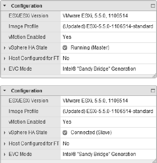
The role of any given ESXi host within a vSphere HA–enabled cluster is noted on the Summary tab of the ESXi host within the vSphere Web Client. The composite screenshot in Figure 7.13 shows how the vSphere Web Client presents this information.
FIGURE 7.13 The status of an ESXi host as either master or slave is provided on the host's Summary tab. Here you can see both a master host and a slave host.
We mentioned that vSphere HA uses the management network as well as storage devices to communicate. In the event that the master cannot communicate with a slave across the management network, the master can check its heartbeat datastores—selected datastores used by vSphere HA for communication—to see if the slave host is still alive. This functionality is what helps vSphere HA deal with network partition as well as network isolation.
Network partition is the term used to describe the situation in which one or more slave hosts cannot communicate with the master even though they still have network connectivity with each other. In this case, vSphere HA is able to use the heartbeat datastores to detect whether the partitioned hosts are still live and whether action needs to be taken to protect VMs on those hosts or initiate an election for a new master within the network partition.
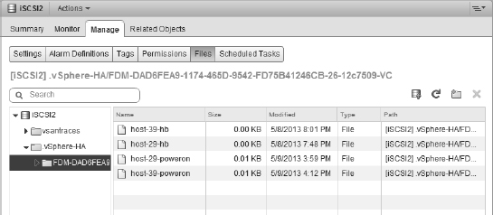
Network isolation is the situation in which one or more slave hosts have lost all management network connectivity. Isolated hosts can neither communicate with the vSphere HA master nor communicate with other ESXi hosts. In this case, the slave host uses heartbeat datastores to notify the master that it is isolated. The slave host uses a special binary file, the host-X-power on file, to notify the master. The vSphere HA master can then take the appropriate action to ensure that the VMs are protected. We'll discuss network isolation and how an ESXi host reacts to network isolation later in this chapter in the section “vSphere High Availability Isolation Response.”
Figure 7.14 shows the files on a VMFS datastore that vSphere HA uses for storage heartbeating between the vSphere HA master and slave hosts.
FIGURE 7.14 vSphere HA uses the host-X-poweron files for a slave host to notify the master that it has become isolated from the network.
In the section “Setting vSphere High Availability Datastore Heartbeating,” we'll show you how to see which datastores are used as heartbeat datastores as well as how to tell vSphere HA which datastores should or should not be used for heartbeating.
With this overview of the vSphere HA architecture and behavior under your belt, let's move on to enabling vSphere HA to protect your VMs.
Enabling vSphere High Availability
To implement vSphere HA, all of the following requirements should be met:
- All hosts in a vSphere HA–enabled cluster must have access to the same shared storage locations used by all VMs on the cluster. This includes any Fibre Channel, FCoE, iSCSI, and NFS datastores used by VMs.
- All hosts in a vSphere HA cluster should have an identical virtual networking configuration. If a new switch is added to one host, the same new switch should be added to all hosts in the cluster. If you are using a vSphere Distributed Switch (vDS), all hosts should be participating in the same vDS.
A TEST FOR VSPHERE HA
An easy and simple test for identifying vSphere HA capability for a VM is to perform a vMotion. The requirements of vMotion are actually more stringent than those for performing a vSphere HA failover, though some of the requirements are identical. In short, if a VM can successfully perform a vMotion across the hosts in a cluster, then it is safe to assume that vSphere HA will be able to power on that VM from any of the hosts. To perform a full test of a VM on a cluster with four nodes, perform a vMotion from node 1 to node 2, node 2 to node 3, node 3 to node 4, and finally node 4 back to node 1. If it works, then the VM has passed the test!
As with earlier versions, vSphere HA is a cluster-level configuration. In order to use vSphere HA to protect VMs, you must first place your ESXi hosts into a cluster. Remember, a VMware cluster represents a logical aggregation of CPU and memory resources. With vSphere HA, a cluster also represents a logical protection boundary. VMs can be protected by vSphere HA only if they are running on an ESXi host in a vSphere HA–enabled cluster. By editing the cluster settings, you can enable the vSphere HA feature for a cluster, as you can see in Figure 7.15.
FIGURE 7.15 vSphere HA is enabled or disabled for an entire cluster.
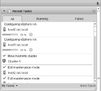
When vSphere HA is enabled for a cluster, it will elect a master as described in the previous section. The other hosts in the cluster will become slave hosts connected to that master host. You can observe this process by watching the Tasks pane of the vSphere Web Client when you enable vSphere HA. Figure 7.16 shows an example of the tasks that are generated when you enable vSphere HA for a cluster.
FIGURE 7.16 As you can see in the Tasks pane, vSphere HA elects a master host when it is enabled on a cluster of ESXi hosts.
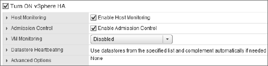
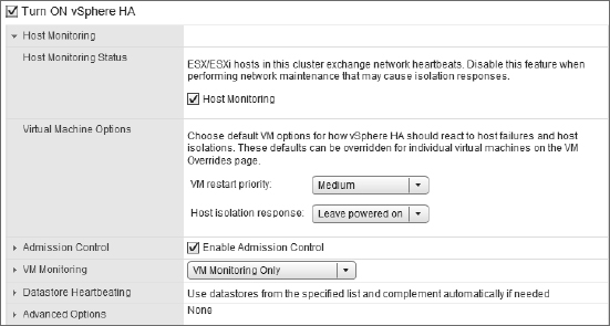
After vSphere HA is enabled, you may occasionally need to temporarily halt it, such as during network maintenance windows. Previously we discussed the behavior of vSphere HA when a network partition or network isolation occurs. If you will be performing network maintenance that might trigger one of these events, uncheck Enable Host Monitoring to prevent vSphere HA from triggering isolation response or network partition behaviors. Note the Enable Host Monitoring check box shown in Figure 7.17; this is how you can temporarily disable the host-monitoring function of vSphere HA during network maintenance so as not to trigger network partition or network isolation behaviors.
FIGURE 7.17 Deselecting Enable Host Monitoring when performing network maintenance will prevent vSphere HA from unnecessarily triggering network isolation or network partition responses.
Configuring vSphere High Availability
After vSphere HA is enabled, configuring vSphere HA revolves around several key areas:
- Admission control and admission control policy
- VM options
- VM monitoring
- Datastore heartbeating
Each of these configuration areas is described in detail in the following sections.
CONFIGURING VSPHERE HA ADMISSION CONTROL
The vSphere HA Admission Control and Admission Control Policy settings control the behavior of the vSphere HA–enabled cluster with regard to cluster capacity. Specifically, should vSphere HA allow the user to power on more VMs than it has capacity to support in the event of a failure? Or should the cluster prevent more VMs from being powered on than it can actually protect? That is the basis for the Admission Control—and by extension, the Admission Control Policy—settings.
Admission Control has two settings:
- Enable: Disallow VM power-on operations that violate availability constraints.
- Disable: Allow VM power-on operations that violate availability constraints.
These options go hand in hand with the Admission Control Policy settings, which we'll explain in a moment. First, though, let's take a closer look at the Admission Control settings.
Consider for a moment that you have a cluster of four identical ESXi hosts. Running on these four ESXi hosts are a bunch of identically configured VMs. These VMs consume a total of 75 percent of the resources in the cluster. This cluster is configured for a single ESXi host failure (we'll go into more detail on these settings in a bit). Further, let's say now you want to power on one more VM, and the resource consumption by that VM will push you past the 75 percent resource usage mark. It is at this point that the Admission Control settings will come into play.
If Admission Control is set to Enabled, then vSphere HA would block the power-on operation of this additional VM. Why? Because the cluster is already at the limit of the capacity it could support if one of the ESXi hosts in the cluster failed (one host out of our four identical hosts is equal to 25 percent of the cluster's capacity). Because you've told vSphere HA to prevent power-on operations that violate availability constraints, vSphere HA will prevent you from starting more VMs than it has resources to protect. In effect, vSphere HA is guaranteeing you that you'll always have enough resources to restart all the protected VMs in the event of a failure.
If, on the other hand, Admission Control is set to Disabled, then vSphere HA will let you power on VMs until all of the cluster's resources are allocated. If there is an ESXi host failure at that point, it's possible that some of the VMs would not be able to be restarted because there are not sufficient resources to power on all the VMs. vSphere HA allowed you to exceed the availability constraints of the cluster.
OVERCOMMITMENT IN A VSPHERE HA–ENABLED CLUSTER
When the Admission Control setting is set to allow VMs to be powered on even if they violate availability constraints, you could find yourself in a position where there is more physical memory allocated to VMs than actually exists.
This situation, called overcommitment, can lead to poor performance on VMs that become forced to page information from fast RAM out to the slower disk-based swap file. Yes, your VMs will start, but after the host gets maxed out, the whole system and all VMs will slow down dramatically. This will increase the amount of time that HA will need to recover the VMs. What should have been a 20- to 30-minute recovery could end up being an hour or even more. Refer to Chapter 11, “Managing Resource Allocation,” for more details on resource allocation and how vSphere handles memory overcommitment.
You should be able to see now how integral the Admission Control Policy settings are to the behavior of Admission Control. When Admission Control is enabled, the Admission Control Policy settings control its behavior by determining how many resources need to be reserved and the limit that the cluster can handle and still be able to tolerate failure.
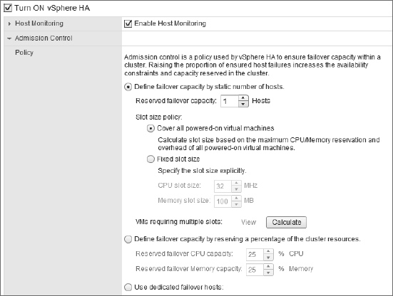
The Admission Control Policy settings are illustrated in Figure 7.18.
There are three options for the Admission Control Policy:
- The first option, Define Failover Capacity By Static Number Of Hosts, allows you to specify how many host failures the cluster should be configured to withstand. Because the ESXi hosts may have different amounts of RAM and/or CPU capacity, and because the VMs in the cluster may have different levels of resource allocation, vSphere HA uses the idea of a slot to calculate the capacity of the cluster. This option also gives you the flexibility to specify the slot size of the cluster. We'll discuss slots in more detail in just a moment.
- The second option, Define Failover Capacity By Reserving A Percentage Of The Cluster Resources, allows you to specify a percentage of the cluster's total resources that should be used for spare capacity in the event of a failure. You can specify different percentages for CPU and memory. The availability constraints are established by simply calculating the specified percentage of the cluster's total available resources.
- The third option, Use Dedicated Failover Hosts, allows you to specify one or more ESXi hosts as failover hosts. These hosts are used as spare capacity, and in the event of a failure, vSphere HA will use these hosts to restart VMs.
FIGURE 7.18 The Admission Control Policy settings will determine how a vSphere HA–enabled cluster determines availability constraints.
BE CAREFUL ABOUT USING FAILOVER HOSTS
When you select an ESXi host as a vSphere HA failover host, it's almost like putting that host into Maintenance mode. vSphere DRS, which we'll describe in more detail in Chapter 12, “Balancing Resource Utilization,” won't place VMs here at startup and won't consider these hosts in its load-balancing calculations. You can't manually power on VMs on the failover host(s) either. These hosts are truly set aside as spare capacity.
For the most part, the Admission Control Policy settings are pretty easy to understand. One area that can be confusing, however, involve slots and slot sizes, which are used by vSphere HA when Admission Control Policy is set to failover capacity by a static number of hosts.
Why slots and slot sizes? vSphere HA uses slots and slot sizes because the ESXi hosts in the cluster might have different configurations: One host might have 8 CPU cores and 24 GB of RAM, while another host might have 12 CPU cores and 48 GB of RAM. Similarly, the VMs in the cluster are likely to have different resource configurations. One VM might need 4 GB of RAM, but another VM might require 8 GB of RAM. Some VMs will have 1 vCPU and other VMs will have 2 or even 4 vCPUs. Because vSphere doesn't know in advance which host will fail and which VMs will be affected by that failure (naturally), vSphere HA needed a way to establish a “least common denominator” to express the overall capacity of the cluster. Once that overall capacity of the cluster can be expressed, vSphere HA can set aside the appropriate amount of resources to protect against the configured number of host failures.
Here's how slots and slot sizes work. First, vSphere HA examines all the VMs in the cluster to determine the largest values for reserved memory and reserved CPU. For example, if one of the VMs in the cluster has a 2 GB memory reservation but all others do not have a memory reservation, vSphere HA will use 2 GB as the value for calculating slots based on memory. In the same fashion, if one VM has a reservation for 2 GHz of CPU capacity but all the other VMs don't have any reservation value, it will use 2 GHz as the value. Basically, vSphere HA constructs the least common denominator as a VM with the largest memory reservation and the largest CPU reservation.
WHAT IF THERE ARE NO RESERVATIONS?
vSphere HA uses reservations, described in Chapter 11, to calculate the slot size. If no VMs have reservations for CPU or memory, vSphere will use the default value of 32 MHz for CPU to calculate slot size. For memory, vSphere HA will use the largest memory overhead value when calculating the slot size. These settings can be seen, grayed out, in Figure 7.18.
Once it has constructed the least common denominator, vSphere HA then calculates the total number of slots that each ESXi host in the cluster could support. Then it determines how many slots the cluster could support if the host with the largest number of slots were to fail (a worst-case scenario). vSphere HA performs these calculations and comparisons for both CPU and memory and then uses the most restrictive result. If vSphere HA calculated 50 slots for memory and 100 slots for CPU, then 50 is the number vSphere HA uses. VMs are then assigned to the slots to determine how many slots are used and how many slots are free, and Admission Control uses this to determine whether additional VMs can be powered on (enough slots remain) or cannot be powered on (not enough slots are available).
The slot-size calculation algorithm just described can result in unexpected settings when you have an unbalanced cluster. An unbalanced cluster is a cluster with dramatically different ESXi hosts, such as a host with 12 GB of RAM along with an ESXi host with 96 GB of RAM in the same cluster. You might also have an unbalanced cluster if you have dramatically different resource reservations assigned to VMs in the cluster (for example, one VM with an 8 GB memory reservation while all the other VMs use much less than that). While you can fine-tune the behavior of the vSphere HA slot-calculation mechanism using advanced settings, it's generally not recommended. For these situations, you have a couple of options:
- You could place similarly sized VMs (or similarly sized hosts) in their own cluster.
- You could use percentage-based availability constraints (via the Percentage Of Cluster Resources Reserved As Failover Spare Capacity setting) instead of host failures or failover hosts.
Using reservations on resource pools might be another way to help alleviate the impact to slot size calculations, if the reservations are necessary. Refer to Chapter 11 for more details on both reservations and resource pools.
The next major area of configuration for vSphere HA is VM options.
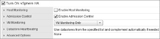
CONFIGURING VSPHERE HIGH AVAILABILITY VM OPTIONS
Figure 7.19 shows the VM options that are available to control the behavior of VMs for vSphere HA. Two VM options are available for administrators to configure: VM Restart Priority and Host Isolation Response. Both options are configurable as a cluster default setting as well as a per-VM setting.
FIGURE 7.19 You can define cluster default VM options to customize the behavior of vSphere HA.
vSphere High Availability VM Restart Priority
Not all VMs are equal. Some VMs are more important or more critical and require higher priority when ensuring availability. When an ESXi host experiences failure and the remaining cluster nodes are tasked by vSphere HA with bringing VMs back online, they have a finite amount of resources before there are no more resources to allocate to VMs that need to be powered on. This is especially true when Admission Control is set to Disabled, allowing more VMs to be powered on than the cluster could support given a failure. Rather than leave important VMs to chance, a vSphere HA–enabled cluster allows you to prioritize VMs through VM Restart Priority.
The VM Restart Priority options for VMs in a vSphere HA–enabled cluster include Low, Medium, High, and Disabled. For VMs that should be brought up first, the restart priority should be set to High. For VMs that should be brought up if resources are available, the restart priority can be set to Medium or Low. For VMs that will not be missed for a period of time and should not be brought online when available resources are low, the restart priority should be set to Disabled. You can define a default restart priority for the entire cluster, as shown in Figure 7.19, but what if there is a VM that is more (or less) important? The VM Overrides section allows you to define a per-VM restart priority. Figure 7.20 shows VM Restart Priority set to Medium for the cluster and set to low for another VM based on their importance to the organization.
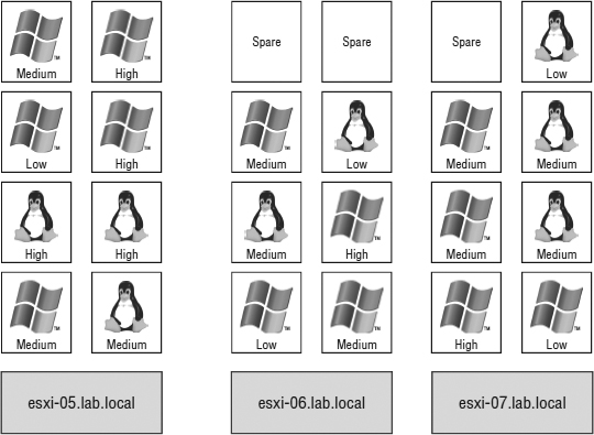
The restart priority is put into place only for the VMs running on the ESXi hosts that experience an unexpected failure. VMs running on hosts that have not failed are not affected by the restart priority. It is possible then that VMs configured with a restart priority of High might not be powered on by vSphere HA because of limited resources, which is in part because of lower-priority VMs that continue to run (again, only if Admission Control was set to Disabled). For example, as shown in Figure 7.21, the ESXi host esxi-05 hosts four VMs with a priority of High and four other VMs with priority values of Medium or Low. Meanwhile, esxi-06 and esxi-07 together hold 13 VMs, but of those VMs only two are considered of High priority. When esxi-05 fails, the FDM master host in the cluster will begin powering the VMs with a High priority. If vSphere DRS is enabled, the VMs will be automatically placed on one of the surviving hosts. However, assume there were only enough resources to power on three of the four VMs with High priority. That leaves a High-priority VM powered off while all other VMs of Medium and Low priorities continue to run on the remaining hosts.
FIGURE 7.20 Use the VM Overrides setting to specify which VMs should be restarted first or ignored entirely.

FIGURE 7.21 High-priority VMs from a failed ESXi host might not be powered on because of a lack of resources—resources consumed by VMs with a lower priority that are running on the other hosts in a vSphere HA–enabled cluster.
At this point, you can still manually remedy this imbalance. Any business continuity plan in a virtual environment built on vSphere should include a contingency plan that identifies VMs to be powered off to make resources available for those VMs with higher priority because of the network services they provide. If the budget allows, construct the vSphere HA cluster to ensure that there are ample resources to cover the needs of the critical VMs, even in times of reduced computing capacity. You can enforce guaranteed resource availability for restarting VMs by setting Admission Control to Enabled, as described previously in the section “Configuring vSphere HA Admission Control.”
vSphere High Availability Isolation Response
Previously, we introduced FDM as the underpinning for vSphere HA and how it uses the ESXi management network to communicate between the master host and all connected slave hosts. When the vSphere HA master is no longer receiving status updates from a slave host, then the master assumes that host has failed and instructs the other connected slave hosts to spring into action to power on all the VMs that the missing node was running.
But what if the node with the missing heartbeat was not really missing? What if the heartbeat was missing but the node was still running? This is the scenario described in the section “Understanding vSphere HA's Underpinnings” when we discussed the idea of network isolation. When an ESXi host in a vSphere HA–enabled cluster is isolated—that is, it cannot communicate with the master host nor can it communicate with any other ESXi hosts or any other network devices—then the ESXi host triggers the isolation response configured in the dialog box shown in Figure 7.19. As you can see, for the entire cluster the default isolation response is Leave Powered On. You can change this setting (generally not recommended) either for the entire cluster here or for one or more specific VMs in the VM Overrides section.
Because vSphere HA uses the ESXi management network as well as connected datastores (via datastore heartbeating) to communicate, network isolation is handled a bit differently starting with vSphere 5.0 than in previous versions of vSphere. In previous versions of vSphere, when a host was isolated it would automatically trigger the configured isolation response. A host considered itself isolated when it was not receiving heartbeats from any other hosts and when it could not reach the isolation address (by default, the default gateway on the management network).
From vSphere 5.0, the process for determining if a host is isolated is only slightly different. A host that is the master is looking for communication from its slave hosts; a host that is running as a slave is looking for updates from the master host. In either case, if the master or slave is not receiving any vSphere HA network heartbeat information, it will then attempt to contact the isolation address (by default, the default gateway on the management network). If it can reach the default gateway or an additional configured isolation address(es), then the ESXi host considers itself to be in a network partition state and reacts as described in the section titled “Understanding vSphere HA's Underpinnings.” If the host can't reach the isolation address, then it considers itself isolated. Here is where this behavior diverges from the behavior of previous versions.
At this point, an ESXi host that has determined it is network-isolated will modify a special bit in the binary host-X-poweron file on all datastores that are configured for datastore heartbeating (more on that in the section titled “Setting vSphere High Availability Datastore Heartbeating”). The master sees that this bit, used to denote isolation, has been set and is therefore notified that this slave host has been isolated. When a master sees that a slave has been isolated, the master locks another file used by vSphere HA on the heartbeat datastore. When the isolated node sees that this file has been locked by a master, it knows that the master is assuming responsibility for restarting the VMs—remember that only a master can restart VMs—and the isolated host is then free to execute the configured isolation response. Therefore, even if the isolation response is set to Shut Down or Power Off, that action won't take place until the isolated slave has confirmed, via the datastore heartbeating structures, that a master has assumed responsibility for restarting the VMs.
The question still remains, though: Should I change the Host Isolation Response setting?
The answer to this question is highly dependent on the virtual and physical network infrastructures in place. Let's look at a couple of examples.
Let's say we have a host in which both the ESXi management network and the VM networks are connected to the same virtual switch bound to a single network adapter (clearly not a generally recommended configuration). In this case, when the cable for the uplink on this vSwitch is unplugged, communication to the ESXi management network and every VM on that computer is lost. The solution, then, should be to shut down the VMs. When an ESXi host determines it is isolated and has confirmed that a master host has assumed responsibility for restarting the VMs, it can execute the isolation response so that the VMs can be restarted on another host with full network connectivity.
A more realistic example might be a situation in which a single vSwitch has two uplinks, but both uplinks go to the same physical switch. If this vSwitch hosts both the ESXi management and VM networks, then the loss of that physical switch means that both management traffic and VM traffic have been interrupted. Setting Host Isolation Response to Shut Down would allow vSphere HA to restart those VMs on another ESXi host and restore connectivity to the VMs.
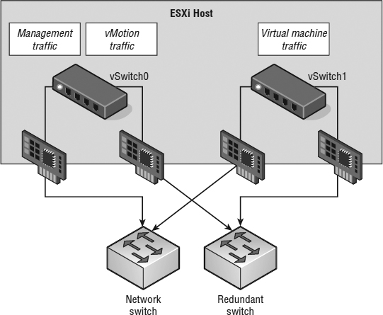
However, a network configuration that employs multiple uplinks, multiple vSwitches, and multiple physical switches, as shown in Figure 7.22, should probably leave Host Isolation Response set to Leave Powered On because it's unlikely that a network isolation event would also leave the VMs on that host inaccessible.
FIGURE 7.22 The option to leave VMs running when a host is isolated should be set only when the virtual and the physical networking infra-structures support high availability.
CONFIGURING THE ISOLATION RESPONSE ADDRESS
In some highly secure virtual environments, management access is limited to a single, non-routed management network. In these cases, the security plan calls for the elimination of the default gateway on the ESXi management network. The idea is to lock the ESXi management network onto the local subnet, thus preventing any type of remote network access to the management interfaces. The disadvantage, as you might have guessed, is that without a default gateway IP address configured for the management network, there is no isolation address to ping as a determination of network isolation status.
It is possible, however, to customize the isolation response address for scenarios just like this. The IP address can be any IP address but should be an IP address that is not going to be unavailable or taken from the network at any time.
Perform the following steps to define a custom isolation response address:
- Use the vSphere Web Client to connect to a vCenter Server instance.
- Open the Hosts And Clusters View, right-click an existing cluster, and select the Settings option.
- Ensure that vSphere HA is selected in the left column and click the Edit button.
- Expand the Advanced Options section and click the Add button.
- Enter das.isolationaddress in the Option column in the Advanced Options (HA) dialog box.
- Enter the IP address to be used as the isolation response address for ESXi hosts that cannot communicate with the FDM master host.
- Click the OK button.
This interface can also be configured with the following options:
- das.isolationaddress1: to specify the first address to try
- das.isolationaddress2: to specify the second address to try
- das.AllowNetwork: to specify a different port group to use for HA heartbeat
So far, you've only seen how vSphere HA handles ESXi host failures. In the next section, we'll show you how you can use vSphere HA to help protect against guest OS and application failures as well.
CONFIGURING VSPHERE HIGH AVAILABILITY VM MONITORING
In addition to monitoring for ESXi host failures and reacting accordingly, vSphere HA has the ability to look for guest OS and application failures. When a failure is detected, vSphere HA can restart the VM. Figure 7.23 shows the area of the Edit Cluster Settings dialog box where you configure this behavior.
The foundation for this functionality is built into VMware Tools, which we'll describe in greater detail in Chapter 9. VMware Tools provides a series of heartbeats from the guest OS up to the ESXi host on which that VM is running. By monitoring these heartbeats in conjunction with disk and network I/O activity, vSphere HA can attempt to determine if the guest OS has failed. If there are no VMware Tools heartbeats, no disk I/O, and no network I/O for a period of time, then vSphere HA—if VM Monitoring is enabled—will restart the VM under the assumption that the guest OS has failed. To help with troubleshooting, vSphere also takes a screen shot of the VM's console right before vSphere HA restarts the VM. This might help capture any sort of diagnostic information, such as a kernel dump or blue-screen STOP error for Windows-based systems.
FIGURE 7.23 You can configure vSphere HA to monitor for guest OS and application heartbeats and restart a VM when a failure occurs.
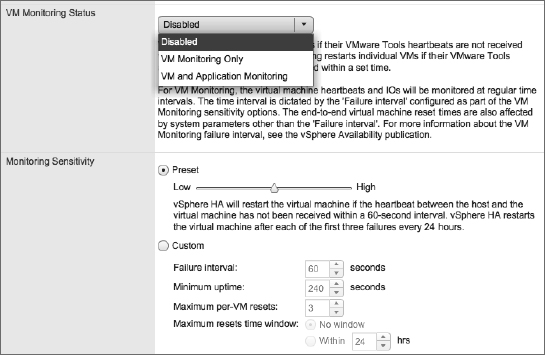
vSphere HA also has application monitoring. This functionality requires third-party software to take advantage of APIs built into VMware Tools to provide application-specific heartbeats to vSphere HA. By leveraging these APIs, third-party software developers can further extend the functionality of vSphere HA to protect against the failure of specific applications. To enable VM or application monitoring, simply select the desired level of protection from the VM Monitoring Status drop-down list shown in Figure 7.23.
If you have enabled VM or application monitoring, you can then adjust the monitoring sensitivity. This slider bar controls how often vSphere HA will restart a VM based on a loss of VMware Tools heartbeats and a lack of disk and network I/O traffic. The slider bar also controls the failure window before which vSphere HA will restart a VM again after a maximum number of failures. Table 7.2 shows the values set by each position on the slider.
TABLE 7.2: VM monitoring sensitivity settings
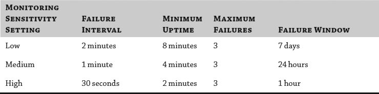
Here's how to read this information:
- Failure Interval: If vSphere HA doesn't detect any VMware Tools heartbeats, disk I/O, or network I/O within this time frame, it will consider the VM failed and will restart the VM.
- Minimum Uptime: vSphere will wait for a set amount of time after the VM has been powered on before starting to monitor VMware Tools heartbeats. This is to ensure that the OS has time to boot and heartbeats stabilize.
- Maximum Failures: This is the maximum number of times vSphere HA will restart a VM within the specified failure window. If Maximum Failures is set at 3 and a VM is marked as failed a fourth time within the specified failure window, it will not be automatically restarted. This prevents vSphere HA from endlessly restarting problematic VMs.
- Failure Window: vSphere will restart the VM only a maximum number of times (Maximum Failures) within this time frame. If more failures occur within this period of time, the VM is not restarted.
If these predefined options aren't sufficient, you can select Custom and specify your own values for Failure Interval, Minimum Uptime, Maximum Per-VM Resets (Maximum Failures), and Maximum Resets Time Window (Failure Window). Figure 7.24 shows a custom VM Monitoring sensitivity configuration.
FIGURE 7.24 The Custom option provides specific control over how vSphere HA monitors VMs for guest OS failure.
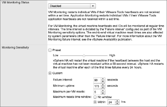
As with other areas of vSphere HA, you also have the option of configuring per-VM monitoring settings. This allows you, on a per-VM basis, to enable or disable VM monitoring and application monitoring sensitivity levels. Thus, if you need VM monitoring for only a few VMs, you can define a default cluster setting and then configure the exceptions accordingly.
The last configuration area for vSphere HA is datastore heartbeating.
SETTING VSPHERE HIGH AVAILABILITY DATASTORE HEARTBEATING
Datastore heartbeating is part of the functionality found in vSphere HA from vSphere 5.0. By communicating through shared datastores when the ESXi management network is not available, vSphere HA provides greater protection against outages due to network partition or network isolation.
This part of the vSphere HA configuration allows you to specify which datastores should be used by vSphere HA for heartbeating. Figure 7.25 shows the Datastore Heartbeating section of the Edit Cluster dialog box.
FIGURE 7.25 Select the shared datastores that vSphere HA should use for datastore heartbeating.
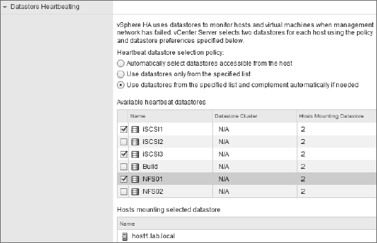
vSphere HA provides three different settings for how the administrator can influence the selection of datastores for heartbeating:
- The first option, Automatically Select Datastores Accessible From The Host, disables the manual selection of datastores from the list. With this option, any cluster datastore could be used by vSphere HA for heartbeating.
- The second option, Use Datastores Only From The Specified List, constrains vSphere HA to using only those datastores selected from the list of datastores. If one of those datastores becomes unavailable for whatever reason, vSphere HA will not perform heartbeating through a different datastore.
- The last option is Use Datastores From The Specified List And Complement Automatically If Needed. This is a bit of a blend of the previous two options. With this option, the administrator selects the preferred datastores that vSphere HA should use. vSphere HA chooses from among the datastores in that list. If one of the datastores becomes unavailable, vSphere HA will choose a different datastore, until none of the preferred datastores are available. At that point it will choose any available cluster datastore.
The last option is probably the most flexible, but how would you know which datastores were being used by vSphere HA? In the next section, “Managing vSphere High Availability,” we'll show you how to tell which datastores vSphere HA is actually using for datastore heartbeating as well as how to determine the slot size, see any cluster configuration issues, and gather information on the total number of protected and unprotected VMs.
Managing vSphere High Availability
Much of what vSphere HA does is calculated automatically: things like slot size, total number of slots, selection of hosts for datastore heartbeating, and the selection of the master/slave roles by FDM are just a few examples. Without proper exposure of these values, it would be difficult for administrators to properly manage vSphere HA and its operation. Fortunately, VMware included information about vSphere HA in the vSphere Web Client to help make it easier to manage vSphere HA.
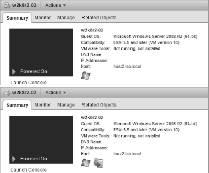
Some of the information is pretty easy to find. For example, the Summary tab of an ESXi host in a vSphere HA–enabled cluster will show the master/slave status, as shown earlier in Figure 7.13.
Similarly, the protected/unprotected status of a VM—indicating that the vSphere HA master has recognized that the VM has been powered on and has taken responsibility for restarting it in the event of a failure—is also noted on the Summary tab of a VM. You can see this in Figure 7.26.
FIGURE 7.26 This blended figure shows the difference between a VM currently listed as Unprotected by vSphere HA and one that is Protected by vSphere HA. VMs may be Unprotected because the master has not yet been notified by vCenter Server that the VM has been powered on and needs to be protected.
However, other pieces of information are found under Cluster ![]() Monitor
Monitor ![]() vSphere HA, as shown in Figure 7.27.
vSphere HA, as shown in Figure 7.27.
THE SUMMARY AREA
The summary area outlines all the relevant details for vSphere HA-enabled clusters. Divided into three sections, in this area you will find:
- Hosts lists the current vSphere HA master and the number of slave hosts connected to the master host. Although the vSphere HA master status is also displayed on the Summary tab for an ESXi host, using this dialog box might be easier and faster for clusters with a large number of hosts.
- Virtual Machines shows the current number of protected and unprotected VMs. This gives you a quick “at a glance” protection summary and is a fast way to determine how many, if any, VMs are unprotected by vSphere HA.
- Advanced Runtime Info exposes the vSphere HA calculations for slot size, total slots in cluster, used slots, available slots, and failover slots. This is very useful information to have. If you have Admission Control set to Enabled and aren't able to power on VMs that you think you should be able to power on, checking this dialog box for the slot size might reveal that the slot size is different than what you were expecting.
FIGURE 7.27 The vSphere HA Summary tab holds a wealth of information about vSphere HA and its operation. The current vSphere HA master, the number of protected and unprotected VMs, and the datastores used for heartbeating is all found here.
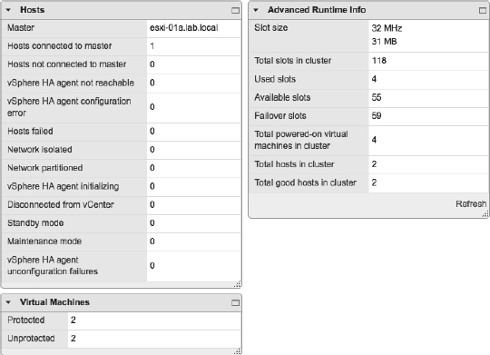
HEARTBEAT DATASTORES AREA
The Heartbeat Datastores area shows which datastores are currently being used by vSphere HA for heartbeating. If you haven't explicitly defined which datastore can or should be used, this is where you can tell which datastores were selected by vSphere HA for heartbeating.
CONFIGURATION ISSUES AREA
In the Configuration Issues area, vSphere HA will display any configuration issues, for example, if the cluster has exceeded the configured failover capacity. You might also see warnings about management network redundancy (if the ESXi management network isn't redundant and protected against single points of failure). Based on the issues displayed here, you can take the appropriate action to correct the problem or potential problem.
vSphere HA is a powerful feature, and we highly recommend its use in every vSphere implementation. However, vSphere HA does rely on restarting VMs in order to provide that level of high availability. What if there are applications for which you need a higher level of availability? vSphere offers that functionality with vSphere Fault Tolerance (FT). Based on VMware's vLock-step technology, vSphere FT provides zero downtime, zero data loss, and continuous availability for your applications.
That sounds pretty impressive, doesn't it? But how does it work? That's the focus of the next section.
Implementing vSphere Fault Tolerance
vSphere Fault Tolerance (FT) is the evolution of “continuous availability” that works by utilizing VMware vLockstep technology to keep a primary machine and a secondary machine in a virtual lockstep. This virtual lockstep is based on the record/playback technology that VMware introduced in VMware Workstation in 2006. vSphere FT will stream data that will be recorded (only nondeterministic events are recorded), and the replay will occur deterministically. By doing it this way, VMware has created a process that matches instruction for instruction and memory for memory to get identical results.
Deterministic means that the computer processor will execute the same instruction stream on the secondary VM so it ends up in the same state as the primary VM. On the other hand, nondeterministic events are functions, such as network, disk, and keyboard I/O, as well as hardware interrupts. So, the record process will take the data stream, and the playback will perform all the keyboard actions and mouse clicks. It is pretty slick to move the mouse on the primary VM and see it also move on the secondary VM.
Before we show you how to enable vSphere FT for a VM, we need to cover some requirements for using vSphere FT. Because vSphere FT is matching instruction for instruction and memory for memory to create two identical VMs running on two different ESXi hosts, there are some fairly stringent requirements for vSphere FT. These requirements exist at three levels: at a cluster level, at a host level, and finally, at a VM level.
vSphere FT has the following requirements at a cluster level:
- Host certificate checking must be enabled. This is the default for vCenter Server 4.1 and later.
- The cluster must have at least two ESXi hosts running the same FT version or build number. The FT version is displayed in the Fault Tolerance section of the ESXi host's Summary tab.
- vSphere HA must be enabled on the cluster. vSphere HA must be enabled before you can power on vSphere FT–enabled VMs.
- VMware EVC must be enabled if you want to use vSphere FT in conjunction with vSphere DRS. Otherwise, vSphere DRS will be disabled on any vSphere FT–enabled VMs.
In addition, vSphere FT has the following requirements on each ESXi host:
- The ESXi hosts must have access to the same datastores and networks.
- The ESXi hosts must have a Fault Tolerance logging network connection configured. This vSphere FT logging network requires at least Gigabit Ethernet connectivity, and 10 Gigabit Ethernet is recommended. Although VMware calls for dedicated vSphere FT logging NICs, NICs can be shared with other functions if necessary.
- The hosts must have CPUs that are vSphere FT compatible.
- Hosts must be licensed for vSphere FT.
- Hardware Virtualization (HV) must be enabled in the ESXi host's BIOS in order to enable CPU support for vSphere FT.
Finally, vSphere FT has the following requirements on any VM that is to be protected using vSphere FT:
- Only VMs with a single vCPU are supported with vSphere FT. VMs with more than one vCPU are not compatible with vSphere FT.
- VMs must be running a supported guest OS.
- VM files must be stored on shared storage that is accessible to all applicable ESXi hosts. vSphere FT supports Fibre Channel, FCoE, iSCSI, and NFS for shared storage.
- A VM's virtual disks must be in thick provisioned (eagerzeroedthick) format or a Virtual mode RDM. Physical mode RDMs are not supported.
- The VM must not have any snapshots. You must remove or commit snapshots before you can enable vSphere FT for a VM.
- The VM must not be a linked clone.
- The VM cannot have any USB devices, sound devices, serial ports, or parallel ports in its configuration. Remove these items from the VM configuration before attempting to enable vSphere FT.
- The VM cannot use N_Port ID Virtualization (NPIV).
- Nested page tables/extended page tables (NPT/EPT) are not supported. vSphere FT will disable NPTs/EPTs on VMs for which vSphere FT is enabled.
- The VM cannot use NIC passthrough or the older vlance network drivers. Turn off NIC passthrough and update the networking drivers to vmxnet2, vmxnet3, or E1000.
- The VM cannot have CD-ROM or floppy devices backed by a physical or remote device. You'll need to disconnect these devices or configure them to point to an ISO or FLP image on a shared datastore.
- The VM cannot use a paravirtualized kernel. Turn off paravirtualization in order to use vSphere FT.
As you can see, vSphere FT has some fairly stringent requirements in order to be properly supported.
vSphere FT also introduces some operational changes that must be taken into account as well:
- It is recommended that power management (also known as power capping) be turned off in the BIOS of any ESXi host that will participate in vSphere FT. This helps ensure uniformity in the CPU speeds of the ESXi hosts in the cluster.
- While you can use vMotion with a vSphere FT–protected VM, you cannot use Storage vMotion. By extension, this means that vSphere FT–protected VMs cannot take advantage of Storage DRS. To use Storage vMotion, you must first turn off vSphere FT.
- Hot-plugging devices is not supported, so you cannot make any virtual hardware changes when a vSphere FT–protected VM is powered on.
NO HARDWARE CHANGES INCLUDES NO NETWORK CHANGES
Changing the settings of a virtual network card while a VM is running requires that the network card be unplugged and then plugged back in. As a result, you can't make changes to virtual network cards while vSphere FT is running.
- Because snapshots aren't supported with vSphere FT, you can't back up VMs using any backup methodology that relies on snapshots. This includes any backup solution that leverages the vSphere Storage API for Data Protection as well as VMware Data Protection. To back up a vSphere FT–enabled VM with one of these tools, you must first disable vSphere FT. Chapter 3 explains how you can set a scheduled task to perform a “Disable FT” and “Enable FT” at a set time frame to suit your backup window.
Be sure to keep these operational constraints in mind when deciding where and how to use vSphere FT in your environment.
Now you're ready to actually enable vSphere FT on a VM. Perform the following steps to enable vSphere FT:
- If the vSphere Web Client is not already running, launch it and connect to a vCenter Server instance. vSphere FT is available only when using vCenter Server.
- Navigate to the Hosts And Clusters or VMs And Templates view. Right-click a running VM and then select Fault Tolerance Turn On Fault Tolerance, as shown in Figure 7.28.
FIGURE 7.28 You can turn on vSphere FT from the context menu for a VM.
ERROR MESSAGE ABOUT “INCORRECT MONITOR MODE” WHEN ENABLING VSPHERE FAULT TOLERANCE
If you receive an error message when attempting to enable vSphere FT for a running VM and the error message mentions an “incorrect monitor mode,” this is probably because your specific CPU family can enable vSphere FT for VMs only when they are powered down. Certain CPU families—most notably, the Intel “Nehalem” or Xeon 55xx series of CPUs—aren't able to enable vSphere FT when the VM is powered on. The workaround is to power the VM off and then enable vSphere FT.
- A pop-up message appears to warn you that enabling vSphere FT will result in several changes. First, all virtual disks will be converted to Thick Provision Eager Zeroed disks, also called eagerzeroedthick disks (virtual disks with all blocks zeroed out ahead of time). Second, vSphere DRS will be disabled for this VM if VMware EVC is not enabled on the cluster. Third, the memory reservation for this VM will be set equal to the configured memory of the VM, as shown in Figure 7.29. Click Yes to turn on vSphere FT for the selected VM.
FIGURE 7.29 Several other configuration changes are enforced when you activate vSphere FT on a VM.
WILL VSPHERE FAULT TOLERANCE DISABLE VSPHERE DISTRIBUTED RESOURCE SCHEDULER FOR A VM?
If VMware EVC is not enabled on the cluster, then vSphere FT will disable DRS for the selected VM when vSphere FT is enabled. If VMware EVC is enabled, then vSphere 5.5 supports the use of vSphere DRS in conjunction with vSphere FT.
- After you have selected to enable vSphere FT, the creation task begins, as shown in Figure 7.30.
If the VM's virtual disks were not already in the Thick Provision Eager Zeroed format, those disks will be converted. Depending on the size of the virtual disks, this might take quite some time.
FIGURE 7.30 vSphere FT must convert existing virtual disks to Thick Provision (eagerzeroedthick) format as it's powering on for the first time.
- Once the process is complete, the VM's icon in the Navigator tree will change. Figure 7.31 shows a VM that has been enabled for vSphere FT.
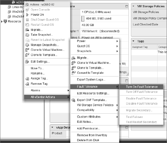
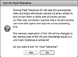
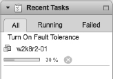
FIGURE 7.31 The darker VM icon indicates that vSphere FT is enabled for this VM.
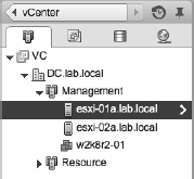
And that's it. It is literally that simple—at least on the surface.
Behind the scenes, after vSphere FT is turned on, vCenter Server will initiate the creation of the secondary VM by using a special type of vMotion. Both the primary and secondary VMs will share a common disk between them, and using VMware vLockstep, vSphere FT will then be able to keep the VMs in sync. vSphere FT uses a network connection between the ESXi hosts to keep the primary and secondary VMs in sync (recall from our earlier discussion of requirements that the ESXi hosts must have a Fault Tolerance logging connection established; Chapter 5 provides more detail on how to configure this network connection). Only the primary VM will respond to other systems across the network, which leaves the secondary VM a silent partner. You can almost compare this to active/passive cluster configuration in that only one node owns the shared network at a time. When the ESXi host supporting the primary VM fails, the secondary VM takes over immediately with no break in network connection. A reverse ARP is sent to the physical switch to notify the network of the new location of the VM. Does that sound familiar? It is exactly what vMotion does when the VM switches to a new host. Once the secondary VM becomes the primary, the creation of the new secondary VM is repeated until the sync is locked. After the sync is locked, as shown in Figure 7.32, you'll see green icons.
FIGURE 7.32 The vSphere Web Client shows vSphere FT status information in the Fault Tolerance area on the Summary tab of a VM.
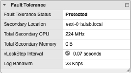
Once you've met the requirements, there isn't any configuration to vSphere FT after you've enabled it.
Before wrapping up this discussion of vSphere FT, we want to discuss using vSphere FT in conjunction with vSphere HA and vSphere DRS. We'll start with vSphere FT and vSphere HA together.
Using vSphere Fault Tolerance with vSphere High Availability
vSphere FT works in conjunction with vSphere HA. Recall that vSphere HA must be enabled on both the cluster and the VM in order to enable vSphere FT. As mentioned previously, if the ESXi host where the primary VM is running fails, the secondary VM takes over and a new secondary VM is created automatically to ensure protection. But what happens if there are multiple host failures?
In the event of multiple host failures, vSphere HA will restart the primary VM. vSphere FT will then re-create the secondary VM on another host to ensure protection.
In the case of a guest OS failure, vSphere FT will take no action because, as far as FT is concerned, the VMs are in sync. Both VMs will fail at the same time and place. vSphere HA VM monitoring—if enabled—can detect the failure in the primary and restart it, and the secondary creation process will start again. Have you noticed a pattern about the secondary VMs? After the sync has failed, the secondary machine is always re-created. This helps avoid any potential split-brain issues with vSphere FT.
ONE OS IMAGE VS. TWO OS IMAGES
Many people misunderstand vSphere FT's behavior when it comes to guest OS failure. If the guest OS in the primary VM crashes, the guest OS in the secondary VM is also going to crash. While these appear to be two separate guest OS instances, they are really one synchronized guest OS instance running in lockstep on two different ESXi hosts. A failure in one will mean a failure in both.
This is markedly different from traditional guest OS clustering solutions, which rely on two separate and distinct guest OS instances. If one of the guest OS instances fails, the other instance is still up and running and can take over for the failed instance. Microsoft Windows Server Failover Clustering (WSFC) is one example of this sort of configuration.
Understanding these differences between guest OS clustering and vSphere FT will help you choose the right high-availability mechanism for your particular application and needs.
Using vSphere Fault Tolerance with vSphere Distributed Resource Scheduler
vSphere FT can also interoperate and integrate with vSphere DRS. However, you must enable VMware EVC for this interoperability and integration to function properly.
When VMware EVC is enabled at the cluster level, vSphere FT can also take advantage of vSphere DRS. When both VMware EVC and vSphere DRS are enabled and set to fully automated, vSphere DRS makes the initial placement recommendations for the fault-tolerant VMs, includes the fault-tolerant VMs during cluster rebalancing calculations and operations, and lets you assign a vSphere DRS automation level to the primary VM (the secondary VM assumes the same setting as the primary VM).
Without EVC, vSphere DRS is set to Disabled for the fault-tolerant VMs, initial placement is provided only for the secondary VM, and neither of the fault-tolerant VMs is included in cluster rebalancing calculations or operations.
Examining vSphere Fault Tolerance Use Cases
vSphere FT is not designed or meant to be run on all your VMs. You should use this service sparingly and take this form of fault tolerance only for your most important VMs. The documentation for VMware's configuration maximums states that there should be no more than four vSphere FT–protected VMs (primary or secondary) on any single ESXi host. Remember, once you have primary and secondary VMs locked and in sync, you will be using double the resources for a protected VM.
Now that we have looked at a couple of high-availability options, let's move on to planning and designing for disaster recovery.
Planning for Business Continuity
High availability is only part of the solution, one component in the bigger picture of business continuity. Business continuity is about ensuring that the business can continue operating in the face of some significant event. High availability deals with business continuity from a fairly narrow perspective: ensuring that the business can continue operating in the event of a physical server failure, an OS or application failure, or a network component failure. There are many more types of failures that you must account for and protect against, but we'll mention two primary ones here:
- First, you'll need to protect against the loss of data due to equipment failure, software malfunction, or simple user error (ever deleted something by mistake?).
- Second, you'll want to ensure that you've done the necessary work around planning for disaster recovery in the event your entire datacenter is rendered unusable or unavailable.
Most organizations have a policy or a set of policies that define the processes, procedures, tools, and technologies that help address these failure scenarios. As you review the information provided in the following sections, you'll want to be sure that any solution you are considering complies with your company's policy for business continuity. If your company doesn't yet have a policy for business continuity, now is a great time to create one!
In the next two sections, we'll look at both of these failure scenarios, along with some of the products and technologies that are applicable. Let's start with data protection.
Providing Data Protection
Backups are an essential part of every IT department's responsibilities, yet they're often the source of the greatest conflict and frustration. Many organizations hoped that virtualizing would make backups easier, and in some ways it has. In other ways, it has made backups more difficult as well. We'll examine the basic methods for backing up VMs and then provide an overview of VMware Data Recovery, a backup solution provided by VMware to help with smaller implementations of vSphere.
EXAMINING VM BACKUP METHODS
There are three high-level methods of backing up VMs in a VMware vSphere environment:
- Running a backup agent of some sort in the guest OS
- Leveraging vSphere snapshots and the vSphere Storage APIs for Data Protection (more popularly known as VADP)
- Using array-based snapshot integration
While various backup applications might have slight variations, the basic methods remain the same. Each of these methods has its own advantages and disadvantages, and no one solution will be the right fit for all customers.
Figure 7.33 illustrates the flow of information when using backup agents inside the guest OS.
FIGURE 7.33 Running backup agents inside the guest OS can provide application- and OS-level integration, but not without some drawbacks.
As you can see from Figure 7.33, running a backup agent within the guest OS affords you OS-level and application-level awareness and integration. The backup agent can leverage the APIs of the guest OS to integrate with the OS and applications running in the OS (for example, by leveraging the Volume Shadow Copy Service in Microsoft Windows). This allows the backup agent to perform very granular backups, such as specific tables within an SQL database, particular mailboxes in Microsoft Exchange, or a subset of files within a Linux filesystem.
However, running backup agents within the guest OS has its drawbacks too:
- The network traffic typically runs across the network, which can create network bottlenecks. This is especially true if the backup traffic runs across the same network as end user–facing traffic.
- To avoid bottlenecks with end user–facing traffic, organizations introduced dedicated backup networks. This means more NICs in the ESXi hosts, separate vSwitches, separate physical switches, additional vNICs in the VMs, and additional complexity in the guest OS and the solution as a whole. Separate backup networks can also complicate troubleshooting and operations.
- The backup agents are individually running in each guest OS instance, so as more and more VMs (and guest OS instances) are consolidated onto physical servers, this creates additional overhead. Given that the overall utilization of the physical hosts was higher anyway because of consolidation, this leaves little headroom for the backup process, which in turn often translates to longer backup windows.
- Some backup vendors charged a separate license for every installation of the backup agent, which has decreased the financial benefits of virtualization and consolidation.
Despite these drawbacks, the tight OS- and application-level integration they offer make backup agents the preferred choice in areas where granularity and application integration are paramount.
The second significant way that you perform backups in the vSphere environment is to operate outside the guest OS. Instead, leverage the snapshot functionality of VMware vSphere to unlock the VM's virtual disks and then back up the virtual disks directly. When the backup of the virtual disk is complete, commit the snapshot and you're finished. The framework for driving this process in an automated fashion—so that backup vendors can make it easier to use—is the vSphere Storage APIs for Data Protection.
The overall process looks something like this:
- The backup software requests a snapshot of the virtual disks for the VM to be backed up.
- VMware vSphere creates a snapshot, and all writes to the virtual disks for that VM now start flowing into the delta disks. The base VMDK files are unlocked.
- The backup application backs up the base VMDK files.
- When the backup of the base VMDK files is complete, the backup software requests vSphere to commit the snapshot.
- The writes in the delta disk are committed to the base VMDK, and the snapshot is removed.
- The process repeats itself for the next VM.
VADP helps provide a standard interface for backup vendors to interact with vSphere for backing up VMs, and it introduces a few other useful features. Changed Block Tracking (CBT), for example, allows vSphere and backup applications to track which blocks in a VMDK have changed and back up only those changed blocks. You can consider CBT the VMDK block equivalent to the archive flag in DOS and NTFS.
Like in-guest backups, VADP-based backups also have advantages and disadvantages:
- There is generally less processor and memory overhead because there's no need to run a backup agent inside every guest OS instance. Depending on the environment, this might allow you to achieve a higher consolidation ratio or provide better performance for your workloads.
- Because there is generally little to no coordination with applications running in the guest OS instances, VADP-based backups typically cannot provide the same level of backup/restore granularity as in-guest backups. There may also be issues ensuring application consistency.
- Depending on how you implement the VADP-based backup solution, file-level restores may be difficult. Some of these solutions require that you restore the entire VM and then manually pull out the individual file or files that need to be restored. Be sure to consider this operational issue in your evaluation.
Numerous backup vendors leverage VADP to perform VM backups. In fact, VMware itself provides an entry-level backup solution that leverages VADP. That solution is called VMware Data Recovery.
IMPLEMENTING VMWARE DATA PROTECTION
VMware Data Protection (VDP) is a disk-based backup and recovery solution. This solution fully integrates with vCenter Server to enable centralized and efficient management backup jobs, and it also includes data deduplication. VDP leverages VADP to streamline the process of backing up VMs.
So, how does VDP work? VDP is composed of three main components. The first component is the VDP virtual backup appliance that will manage the backup and recovery process. The second component is the user interface plug-in for vSphere Web Client. The third and last component is the deduplicated destination storage, which is a predetermined sized VMDK within the VDP virtual backup appliance, with the available sizes being 0.5 TB, 1.0 TB, or 2.0 TB.
Once the VDP virtual backup appliance has been installed, using the vSphere Web Client, select the Backup tab on the VMs that you want to protect. You can then schedule the backup job and configure the data-retention policy. vCenter Server will then send the job information to the VDP virtual backup appliance to start the backup process by initiating the point-in-time snapshots of the protected VM. Like its predecessors, VDP frees up network traffic on the LAN by mounting the snapshot directly to the VDP virtual backup appliance. After the snapshot is mounted, the virtual appliance begins streaming the block-level data directly to the destination storage. It is during this streaming process, before the data gets to the destination disks, that the VDP appliance will deduplicate the data to ensure that the redundant data is eliminated. After all the data has been written to the destination disk, the VDP appliance will then dismount the snapshot and apply the snapshot to the VM.
Backups are no good if you can't recover the data, naturally. With VDP, the recovery process is a point-in-time file-level or complete system restoration. The VDP virtual backup appliance will retrieve and stream the specific blocks of data that are needed for the restore. The virtual appliance will efficiently transfer only data that has changed. This speeds up and streamlines the process. When restoring a single file, or performing a file-level restore, the process is initiated from inside the VM console.
In the end, the method you use to provide data protection isn't what's important. What's important is that you do provide data protection for your virtualized datacenter.
USING YOUR STORAGE ARRAY TO PROTECT DATA
Many of the storage vendors have started adding the ability to do point-in-time snapshots of data on the array. The specifics of how the snapshots work will vary from vendor to vendor, and—as with so many other aspects of IT—there are advantages and disadvantages to each approach. The result of this functionality is the ability to hold point-in-time views of your company's information for a predetermined amount of time. This time frame could be hours, days, weeks, or months depending on the amount of disk space you have provided for this. These snapshots can serve as a “first line of defense” in data protection. Here's an example. Let's say a VM was deleted by accident. With point-in-time restore, you can dial back in time to right before the VM was deleted. Mount the LUN from that specific moment in time, and restore your VM. While not traditionally thought of as a suitable replacement for other backup solutions, array-based snapshots and even array replication are starting to make a lot more sense. As data footprints continue to grow and businesses demand more aggressive recovery point objectives (RPOs) and recovery time objectives (RTOs), traditional backup solutions can struggle to meet business needs. Array capabilities have continued to mature and now offer a number of different business continuity and disaster recovery options such as offsite replication and offloading to lower storage tiers.
Recovering from Disasters
High availability makes up only half of the ability to keep your application/systems up in day-to-day operation. The other half is disaster recovery, which is the ability to recover from a catastrophic failure. The risks posed by hurricanes, earthquakes and other natural (and man-made) disasters underscore how important it is to establish a thoughtfully designed plan that you can execute with certainty. Entire datacenters can be destroyed by one of these events, and even the datacenters that survive and keep functioning do not stay operational for long when generators run out of gas. When real events like Hurricane Katrina occur, the aftermath drives the point home that businesses need to be prepared.
Before virtualization, the disaster recovery (DR) team showed up, and the remote recovery site was slated with the task of recovering the enterprise in a timely manner. A timely manner back then was at least a few days to build and install the recovery servers and then restore the enterprise from the backup media.
Sounds simple, right? Well, in theory, it is supposed to be, but problems always occur during the process. First, during the recovery process, you can rarely restore your environment at the remote datacenter location to the same make and model that you run in your current environment. Thus, after you restore your data from your backup media, you are greeted with the pretty blue screen that announces that the drivers are different. For the most part, after the restore completes, you can rerun the installation of the drivers for the recovery servers, but Murphy tends to show up and lay down his law.
Second, the restore process itself is another form of literal contention. If your backup strategy does not consider which servers you want to recover first, then during a disaster, when you try to restore and bring up systems based on importance, you waste a lot of time waiting for tape machines to become available. This contention becomes even worse if your backups span more than one tape. Speaking of tapes, it is not uncommon for tapes to become corrupt and unreadable. Backups are completed and the tapes are sent off site but not tested until they are needed. If all goes well, you might finish your backup in a few days, but success can be elusive.
Today, a majority of data is kept on the SAN, and the data is replicated to another SAN at your remote disaster recovery co-location site. So, your data is waiting for you when you need to perform a recovery, which really speeds up the process. At first this remote replication was an expensive undertaking because only the high-dollar enterprise SANs had this capability. Over the years, though, this approach has become the standard, and software solutions have started enabling similar functionality without the need for matching hardware at each endpoint.
To set up SAN replication, a company purchases two SANs to be set up at different locations, and the data is replicated between the two sites. Many vendors offer replication solutions, and the particulars of these replication solutions vary. Some replication solutions use Fibre Channel (or Fibre Channel over IP, FCIP); others use standard TCP/IP connections. Some replication solutions support only that vendor's storage arrays (like EMC SRDF or NetApp SnapMirror), while other replication solutions support heterogeneous storage environments. Some replication solutions allow for replicated data to be “split off” for other purposes (might be good for backups); others don't have that functionality.
In spite of these differences, all replication solutions fall into one of two very broad buckets:
- Synchronous replication solutions
- Asynchronous replication solutions
In synchronous replication solutions, the primary array waits until the secondary array has acknowledged each write before sending a write acknowledgement back to the host, ensuring that the replicated copy of the data is always as current as the primary. In this situation latency comes into play, and it increases significantly with distance. Therefore, you must limit the distance between synchronous replication solutions to keep latency to a minimum.
Asynchronous replication solutions transfer data to the secondary array in chunks and do not wait for a write acknowledgement from the remote array before acknowledging the write to the host. Using this method, the remote copy of the data will never be as current as the primary copy, but this method can replicate data over very long distances and with reduced bandwidth requirements.
In a vSphere environment, you can combine SAN- and/or host-based replication—synchronous or asynchronous—with VMware Site Recovery Manager (SRM), a workflow automation tool that helps administrators with the task of orchestrating the startup of all the VMs in a datacenter. SRM is a great product but well outside the scope of this book. However, you can refer to the VMware SRM website at www.vmware.com/products/site-recovery-manager/ for more information.
VSPHERE HIGH AVAILABILITY FAILOVER WITH SYNCHRONOUS REPLICATION?
Earlier in this chapter we told you that you could not perform HA failover to another site. As a general rule, this is true—even with synchronous SAN replication. Although synchronous SAN replication ensures that the data in the remote site is always up-to-date, every traditional replication product on the market today marks the replication target as read only. This means that you can't fail over via vSphere HA because the target datastore is read-only. As new solutions are brought to market that enable read/write access to storage in multiple locations at the same time, this ability becomes a reality.
While SAN-based replication is great, there may be times when it's just not feasible. For smaller businesses or remote offices, the size and cost of the infrastructure cannot be justified. Inevitably, DR is still a requirement, and for this reason, VMware has an IP-based replication engine simply called vSphere Replication.
Using vSphere Replication
The ability to make a copy of your important data and workloads at a remote location is often one of the top priorities for business management. They realize that recovering important workloads and data is crucial to keeping the business operating, and the quicker they can be up and running, the less productivity they potentially lose. As discussed in the previous section, “Recovering from Disasters,” replicating data from your primary location to a secondary location can be performed using SAN-based replication, but this can be a costly solution. The other option available to VMware administrators is the built-in vSphere Replication.
vSphere Replication was introduced in SRM 5.0 and decoupled as a new feature in vSphere version 5.1, and it has been further improved in version 5.5. It provides VM-based replication and recovery at the hypervisor level. This means that there are no external requirements to provide the replication, apart from network connectivity between two locations. Available for every license level above Essentials Plus, vSphere Replication can copy VMs within the same cluster or to a different cluster, which means your target and source could be either the same vCenter or a completely different vCenter on the other side of the country! Before we show you how to configure vSphere Replication, let us explain the architecture and limitations around this feature.
As mentioned earlier, vSphere Replication can be configured regardless of the underlying storage system or protocol. It will work with locally attached SATA, Fibre Channel SANs, or IP-based NASs. vSphere Replication has no preference of type and is even flexible enough for the source and destination to differ in storage configuration, as shown in Figure 7.34.
FIGURE 7.34 vSphere Replication can work between datacenters, as long as there is a network joining them.
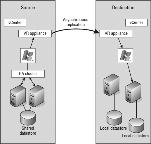
The following constraints affect how vSphere Replication can be configured:
- Maximum replication time (RPO): 24 hours
- Minimum replication time (RPO): 15 minutes
- Maximum protected VMs: 500/instance
- Maximum instances: 10/vCenter Server
vSphere Replication is installed by deploying a virtual appliance to extend the feature set within vSphere. The installation is much like that of vCenter Operations Manager or the vSphere Management Assistant. Let's step through the installation process, and then we'll show you how to configure a VM to replicate to a different cluster under a single vCenter Server instance.
- If the vSphere Web Client is not already running, launch it and connect to a vCenter Server instance.
- Right-click a cluster or datacenter object, and select Deploy OVF Template.
- Browse to the local file where you downloaded the vSphere Replication appliance OVF file. Click Next to proceed to the next screen.
- Review the details to ensure that they are correct. Click Next to move onto the EULA screen.
- Click the Accept button, and then click Next to continue.
- Choose a name and location for the appliance, then click Next.
- Decide on the storage format, remembering that the appliance doesn't hold any of the replication data itself.
- Choose the appropriate network configuration. As you can see in Figure 7.35, we have selected a static IP assignment.
FIGURE 7.35 The network configuration for the vSphere Replication appliance hap-pens before it is deployed.
- Configure the appliance password and static IP (if selected previously) on this page. Click Next to continue.
- On the second to last screen you will be asked to choose a vCenter service for the vSphere Replication appliance. In this case, we only have one. Click Next to continue.
- Review the selections and then click the Finish button to commence the deployment.
- Once the vSphere Replication appliance has finished deploying, power it on as you would any VM.
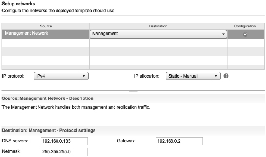
On the main vSphere Web Client home page, a new icon has been created labeled vSphere Replication. Within this section you can monitor existing replication jobs and configure target sites. Most of the actual configuration happens when you want to set up a VM for replication. Adding additional sites is as simple as deploying another vSphere Replication Virtual Appliance and then adding it into Target Sites. For simplicity, let's assume we only have a single site and we want to configure a local replication of a VM:
- If the vSphere Web Client is not already running, launch it and connect to a vCenter Server instance.
- Open the Hosts And Clusters or VMs And Templates view.
- When you right-click a VM, there is now an additional menu at the bottom labeled vSphere Replication. Within this menu, select Configure Replication as shown in Figure 7.36.
FIGURE 7.36 New menus are often added in the vSphere Web Client when virtual appliances that add functionality are deployed.
- When the Configure Replication dialog box appears, select the target site. In this case, the only site is the local one.
- The next screen allows you to choose a replication server appliance. Select Auto-Assign and click Next.
- On the Target location screen, you are able to pick the datastore that you wish the replica to reside on. Choose this wisely because you could fill this datastore with replication data, depending on your RPO schedule. Click Next to continue.
- The Replication options let you pick a guest OS quiescing method, with Microsoft Shadow Copy Services (VSS) as the only available option. Quiescing will ensure that the VSS-aware applications running on the VM have flushed all their cached data to disk before taking a copy.
- The Recovery Settings page is the most important settings page because this is where you set the frequency of replication and how many copies to keep. Set your RPO to 8 hours and the point-in-time instances to 3/day for 5 days, as shown in Figure 7.37.
FIGURE 7.37 Always configure the recovery settings within vSphere Replication to match (or exceed) your application's RPO requirements.
- On the final page, review all the settings and click Finish.
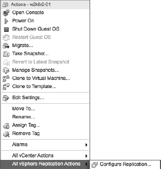
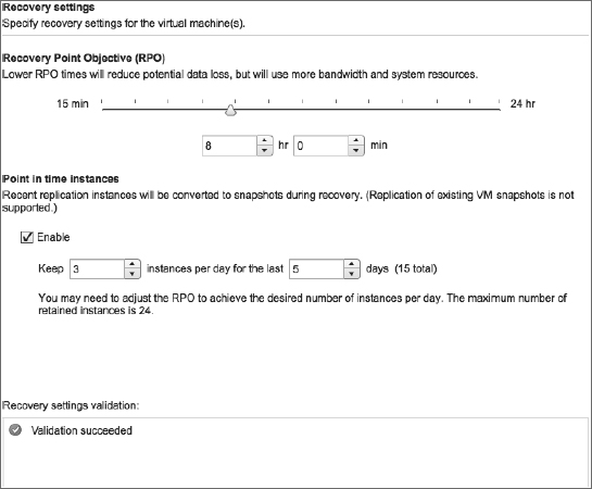
Your VM will now be replicated to the site and datastore as per the replication settings. If at some stage you need to recover the VM, simply click the vSphere Replication icon on the vCenter home screen, find the VM in the Replications lists, and select Recover. You will then be asked for a destination to recover to. Keep in mind that when recovering VMs, initially they are powered on without being connected to any port groups. This ensures that if they are recovered while another copy exists on the network, there will not be any conflicts.
In this chapter, we explained that high availability is for increasing uptime and business continuity is about ensuring that a business can continue in the event of a significant adverse event. The bottom line, to be blunt, is that you'd better have both in place in your environment. High availability is an important part of any IT shop, and you should design and create a solution with proper care. However, you cannot stop there; you absolutely must test, test, and test again any solution to make sure that your solution works as designed and, most important, that it will work when you need it.
The Bottom Line
Understand Windows clustering and the different types of clusters. Windows clustering plays a central role in the design of any high-availability solution for both virtual and physical servers. Microsoft Windows clustering gives us the ability to have application failover to the secondary server when the primary server fails.
Master It Specifically with regard to Windows clustering in a virtual environment, what are three different types of cluster configurations that you can have?
Master It What is the key difference between NLB clusters and Windows failover clusters?
Use vSphere's built-in high-availability functionality. VMware Virtual Infrastructure has high-availability options built in and available to you out of the box: vSphere High Availability (HA) and vSphere Fault Tolerance (FT). These options help you provide better uptime for your critical applications.
Master It What are the two types of high-availability options that VMware provides in vSphere, and how are they different?
Recognize differences between different high-availability solutions. A high-availability solution that operates at the application layer, like Oracle Real Application Cluster (RAC), is different in architecture and operation from an OS-level clustering solution like Windows failover clustering. Similarly, OS-level clustering solutions are very different from hypervisor-based solutions such as vSphere HA or vSphere FT. Each approach has advantages and disadvantages, and today's administrators will likely need to use multiple approaches in their datacenter.
Master It Name one advantage of a hypervisor-based high-availability solution over an OS-level solution.
Understand additional components of business continuity. There are other components of ensuring business continuity for your organization. Data protection (backups) and replication of your data to a secondary location are two areas that can help ensure that business continuity needs are satisfied, even in the event of a disaster.
Master It What are three methods to replicate your data to a secondary location and what is the golden rule for any continuity plan?