Chapter 6
Parameters
The Autodesk® Revit® platform is sometimes referred to as a parametric change engine. Parameters are the very core of what makes Revit MEP such a powerful design and modeling tool. Parameters hold the computable data that defines the properties of not only model components but also everything that makes up a Revit project. They are the characteristics of all elements of a Revit project that ultimately determine behavior, appearance, performance, and information.
Parameters and properties are often considered synonymous, but it is the parameters that hold the information we store in elements; they determine the properties of a component. Properties may be static, but parameters allow for change to be propagated throughout the project.
When you realize the power of parameters in Revit and understand the types of things you can achieve with them, you will have a better understanding of why Revit can improve your workflow processes and the efficiency of your design projects.
In this chapter, you will learn to do the following:
- Manipulate the properties of parameters
- Work with type catalogs
- Work with shared parameters
- Use parameters in project files
Understanding Parameter Basics
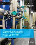
Before you can understand how to use parameters to drive the properties of your objects, you need to understand the properties of parameters. When you create a parameter to hold some form of computable data, you want to define the way in which it will do so. Figure 6.1 shows the Parameter Properties dialog box accessed from within the Family Editor. Other versions of this dialog box that contain additional settings are discussed later in the chapter. This dialog box is the first place to go when adding a parameter to a family, a project, or a schedule.
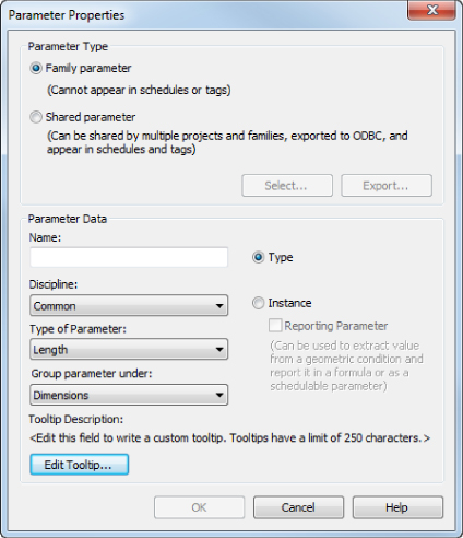
Figure 6.1 Parameter Properties dialog box
There are four basic kinds of parameters in Revit MEP: system parameters, family parameters, project parameters, and shared parameters. Some parameters are hard-coded into the software. The values of these parameters can be edited as needed, but the parameters themselves cannot be removed or modified. In this chapter, these are referred to as system parameters.
Family parameters are used to build and define graphical structure and engineering data within component families. These parameters can be customized as needed to enhance the capabilities of component objects and to extract and analyze data.
Shared parameters are useful to help maintain consistency within families and to coordinate information within a project. They are the most useful kind of parameter because they can be used in component families, schedules, tags, and annotations to report the same data in whichever format the user chooses.
Project parameters exist only in the project environment, as the name suggests. They can appear in schedules but not in tags. Their main advantage is that you can apply them to all families of a particular category or even multiple categories in a project instead of having to add the same parameter to every family. Project parameters can be created from the Project Parameters tool under the Manage tab.
Choosing the Correct Parameter
The first decision to make is what type of parameter to create. Family parameters can be created when working in the Family Editor, and they will be visible in a project when the family is selected. However, the information that they hold cannot be used in schedules or reported by a tag or annotation. Shared parameters can be used the same way that family parameters are used, but they are unique in that they can also be used in schedules and tags. However, this rule has its exceptions. For example, in a detail component family, you can't create shared parameters; you can create only family parameters. But family parameters created in a detail component family can appear in schedules yet still not in tags. Parameter types are discussed in further detail later in this chapter.
Naming Parameters
When you choose to add a parameter, it is likely that you have a specific purpose for it. That may sound like an obvious statement, but it is important to consider when you decide what to name the parameter. There is no harm in naming your parameters in a descriptive manner, especially when you are working with others who need to understand the purpose of a parameter. However, it is possible to be too verbose. Long parameter names can cause the annoyance of having to resize columns within dialog boxes in order to read the name.
Consistency is the key to good parameter naming. It can be frustrating to go from one family to another and see different names for parameters that provide the same information. Using descriptive words is also helpful, especially when you have similar parameters within the same object, such as a component that is made up of multiple shapes, each requiring a Width parameter. It can be difficult to work with parameter names such as W1, W2, W3, and so on, whereas using names such as Housing Width, Lens Width, and Bracket Width makes it easier to make adjustments or changes when working in the Properties palette or Type Properties dialog box of the object.
If you intend to abbreviate measurements such as length, height, or radius, be sure to use a consistent format. Will you use the abbreviation as a prefix or suffix to the descriptive portion of the name? Will punctuation such as dashes or parentheses be used? These symbols can have an effect on how those parameters perform in formulas.
Decide up front whether you will use height or depth to describe the third dimension of an object. The way you orient the families can also create inconsistency in parameter usage. What could be width for one family may be length for another. You can avoid this issue by considering the orientation of the family and where the parameters go.
There are two general systems for naming the parameters representing the three dimensions—either keep the parameter name meaningful to the family or always keep it consistent. So, if you were to use the first method (keep it meaningful), you would call the parameter's depth, height, or width based on what makes the most sense for the particular family. And if you were to go with the second method (always consistent), you would always call the three directions of the family the same—length, width, and height. In some cases, the length really may be width, and in others the width really may be depth. But if you are consistent and everyone at your company understands the concept, it all makes sense. In Figure 6.2, you can see a family that uses a consistent naming convention for the three main dimensions. From plan view, the horizontal parameter will always be called LENGTH, the vertical will always be called WIDTH, and the third parameter will always be called HEIGHT.
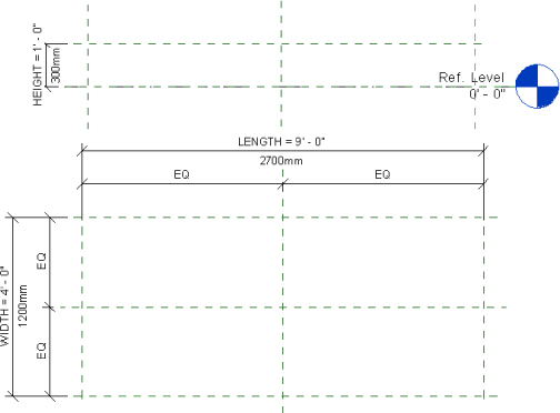
Figure 6.2 Choosing parameter names
In addition, in this case all caps is used for the naming convention, which helps users to quickly spot any custom parameters in the Properties palette, although there are other ways to achieve this. For example, you can use an abbreviation of your company's name before or after the parameter name, such as MyCo_Length or Height_MyCo. Autodesk capitalizes the first letter of each word when developing parameters names (this is called title case or headline style), and this is the default for standards such as the Autodesk Revit Model Content Style Guide (http://seek.autodesk.com/MarketingSolutionsRevitStyleGuide.htm), Australian and New Zealand Revit Standards (www.ANZRS.org), and the bimstore Standards (https://https://www.bimstore.co.uk/uploads/bim-types/bibles/bimstore-bible-revit-new.pdf). Whichever you choose for your own standard, the key is to be consistent and stick to it.
Parameter naming is important because Revit is case sensitive and context sensitive when you refer to a parameter in a formula, calculated value, or filter. Spelling and capitalization accuracy are critical, so develop a naming convention that is as simple as possible while still being easily understood.
Using Type Parameters
Type parameters are the reason you can have multiple variations of a family within one file. Family types drive type parameters that are common to the host family, but potentially unique to each family variation - or ‘type’. When you are creating a parameter, it is important to decide whether the parameter will be used to define a type within the family.
Type parameters can cause the most damage when misused because they enact changes to every instance of the family type to which they belong. For this reason, you will receive a warning when editing a type parameter in a schedule view, and accessing a type parameter in a model view requires an extra mouse click. However, you can customize the double-click function of the mouse to access the type properties. This can be done from Application ![]() Options
Options ![]() User Interface.
User Interface.
In some cases, you may choose to use instance parameters instead of type parameters, and we'll be discussing that shortly.
Type parameters do require that if you need to change just one or a few instances of an object, you will have to create a new family type. This can lead to having several types within a family, which causes your Type Selector to be cluttered and confusing. If you are creating a type parameter that will define a family type, it is best to name the family type as it relates to the value of the type parameter(s). A light fixture family, defined by its width and length parameters, would likely have family types with names such as 2′ × 4′ (600 mm × 1,200 mm) and 1′ × 4′ (300 mm × 1,200 mm), for example.
Type parameters also allow you to create type catalogs for families with extensive lists of parameter configurations. We will address type catalogs a little later.
Using Instance Parameters
Instance parameters provide the most flexibility for editing an object. They are easily accessed via the Properties palette when an object is selected. Create instance parameters for values that you want to be able to change for just the selected object. To use the example of a finish color, if the color is an instance parameter, then you could have one family type that could vary in color without having to create a separate family type for each color option. Another example is the Air Flow parameter for diffusers. You may use the same diffuser multiple times in your project, but the air flow they supply from one room to another most likely will vary.
The drawback to instance parameters is that they apply only to the selected objects. Thus, if you want to change an instance parameter value for all instances of an object, you will have to select each object and change it individually. Alternatively, you can select objects by using schedules or by right-clicking an object and choosing Select All Instances. Make sure you understand the difference between the options Visible In View and In Entire Project. Figure 6.3 shows the difference between these two options.
Figure 6.3 Selecting all instances
An instance parameter can be set to be a reporting parameter. A reporting parameter will hold a value that can be used in formulas for other parameters, or it can be used to drive the behavior of another parameter. These are most useful in wall- or ceiling-hosted families because, for example, you can use a reporting parameter to recognize the thickness of the host wall. Some portion of a dimensional reporting parameter must be associated to the host in order to be used in a formula. These parameters have a very narrow range of application, especially for the MEP disciplines. It may take a while until you find a purpose for them. In most cases, beginner Revit users create them by mistake and get even more confused about why the parameter doesn't work as expected.
Once you have defined a parameter as either instance or type, you can change it if required for the desired behavior. Just keep in mind that Revit will not let you change a type parameter to an instance parameter if that parameter is used in a formula of a type parameter. The rule of thumb is that instance parameters can't “drive” type parameters. Thus, it is best to know up front what kind of parameter to create.
Setting Parameter Discipline, Type, and Grouping
The Discipline drop-down list in the Parameter Properties dialog box contains the different disciplines that can be assigned to a parameter. Parameter discipline is important for defining the measurement units that the parameter value will have. Figure 6.4 shows the drop-down list of available disciplines.
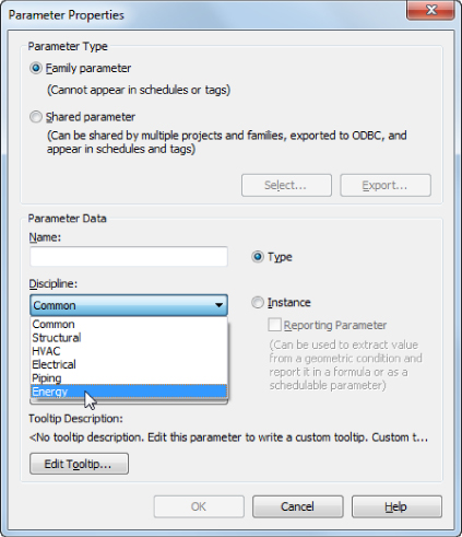
Figure 6.4 Parameter discipline options
The Type Of Parameter option in the Parameter Properties dialog box is directly related to the chosen discipline. Each discipline has a unique set of parameter types that relate to the various units of measurement for that discipline.
Figure 6.5 shows the Type Of Parameter options for the Common discipline. Notice that many of the types are the same as in the Project Units settings for the Common discipline of a project, such as Length, Area, and Volume.
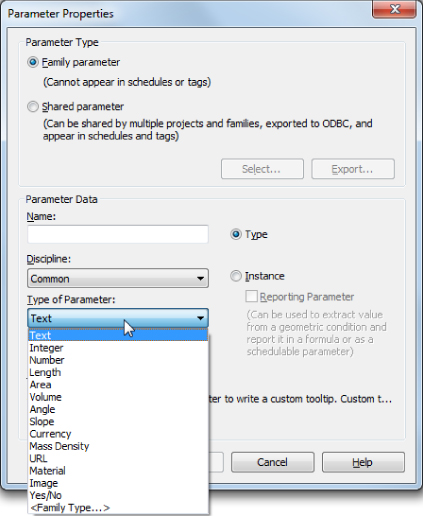
Figure 6.5 Type Of Parameter options for the Common discipline
There are additional options for parameter values that are not a unit of measurement. The Text option allows you to input anything for the value of the parameter. This is the most versatile option, but from an engineering standpoint, it offers the least amount of “intelligence” because a text string provides only information, not computable data. If the parameter value doesn't have specific units and will always be numbers, it is best to use Number instead of Text; this will allow you to use it in formulas if you ever need it. If you are creating a parameter that is scheduled and want the ability to input either numbers or text or a combination of characters, then the Text option is best.
The <Family Type…> option for a parameter is a useful tool when you have multiple nested families within a family. You can create a Family Type parameter to toggle between all the nested families. When the host family is loaded into a project, the parameter can be modified to display any of the nested families by selecting from the list in the Family Type parameter. Figure 6.6 shows an annotation family for graphic scales with several nested annotations loaded. A Family Type instance parameter has been created to allow the use of any of the nested families.
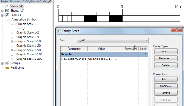
Figure 6.6 Family using Family Types parameter
You can use the Yes/No option if your parameter requires a simple yes or no value. The value for this type of parameter appears as a check box in the Properties palette, and it can be used to control the visibility of objects or to verify that a condition exists. In schedules, a Yes/No parameter appears as Yes, No, or a blank field. By default, Yes/No parameters are selected and grayed out in the Properties palette, which means it's in a limbo state that is neither yes nor no; this is when it will appear as a blank field on a schedule.
Other disciplines have options for Type Of Parameter that relate to units of measurement. When you select a specific Type Of Parameter setting, the value used for the parameter must be consistent with the unit of measurement. For example, if you choose the Air Flow option for the HVAC discipline, you could not input any value other than a number consistent with the unit of measurement you are using for airflow. This can cause problems with schedules when an object does not have a value for this parameter and you want to use something such as N/A or a dash to indicate that the value is not actually 0.
By default, the Type Of Parameter option is set to Length. This was introduced in Revit MEP 2011, whereas in older versions the default was Text. In older versions, it was easy to overlook this setting because of the versatility of the Text type, but with Length being the default now, Revit defaults to the most common parameter, but it is still important to set the proper type if Length is not what you need.
You can determine where the parameter will show up in the Properties palette or the Type Properties dialog box of an object, as shown in Figure 6.7. However, Revit will make a best guess, placing the HVAC/Airflow parameter into the Mechanical – Airflow group or the Electrical/Luminous Flux parameter into the Photometrics group, for example. The user can override this but should consider other users and content creators. If you are using shared parameters, it may well be a best practice to accept the defaults, unless the company documentation is very good. This will lead to less confusion because coworkers will know where to find similar data in families and projects.
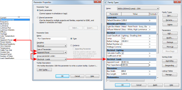
Figure 6.7 Parameter groups
The option for grouping parameters is sometimes confusing to people because they think that it is related to the Type Of Parameter setting. The Group Parameter Under setting does not have any bearing on the Type Of Parameter and Discipline settings, so you could have a Duct Size parameter that is placed in the Identity Data group. Parameter grouping is another area in which being consistent is important to improved workflow and efficiency. You want to be able to find your parameters in the same location for each family while editing in your model. If you are not going to use the default for Group Parameter Under all the time, it may be a good idea to take it a step further and create a company-standard document that outlines what Type Of Parameter setting goes in what Group Parameter Under setting. By finding the same parameters always in the same group, your users will be more efficient and comfortable with your company families.
New to Revit MEP 2015 is the ability to either sort parameters alphabetically (Ascending or Descending) or move them by using the additional buttons available in the Family Types dialog, as shown in Figure 6.8. When new parameters are added to a new family, they are automatically sorted alphabetically. If a family is upgraded from a previous version, the user then has the ability to sort the parameters with the Ascending or Descending buttons. Once the parameters are sorted, you can move each parameter up or down within each group. This means important parameters can be pushed to the top of a group, even though you may have sorted them alphabetically.
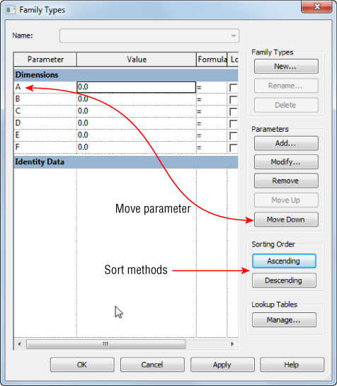
Figure 6.8 Parameter sorting
The current version of Revit does not allow users to customize any of these pull-downs. This creates challenges with various units that may need to exist at the same time in the project. A good example for that is the Power unit of measurement; it can be watts, BTU per second, horsepower, and a few more choices. But in a real project, chances are you will want to use horsepower for motors, watts or volt-amperes for electricity distribution, and maybe kilowatts for the entire building or major blocks of the building. In reality, you can't do that with Revit.
If you create a family that uses different units for certain parameters, the family units will be changed after it is loaded into the project. This is a significant roadblock for achieving true BIM because there are industry standards for the units (W, VA, KW, and so forth) that need to be used for a specific parameter. In most cases, the information (the I in BIM) becomes second in priority in order to complete the project in a biddable and readable fashion, which in many cases would involve using either numbers or text parameters instead of actual units. As a result of such workarounds, you may not be able to circuit certain devices or show their load on the panel schedules unless the chosen units are the same for the entire project.
Using Parameters in Families
Many parameters are created when working in the Family Editor. As content is planned, created, or edited, it becomes clear which type of data is needed for either analysis or reporting or to drive the geometry. When you're working with Revit families, you'll come across the term flexing, which essentially means changing dimensional parameter values to test whether a family is parametric (flexible) and can take various parameter values without being broken. Flexing a family can be done through the Family Types dialog box, by modifying a series of parameters and clicking OK. Another way to flex a family is to modify the parameter value directly in a plan view or any other view. All you need is to select the parameter and enter a different value for it. A third method of flexing a family is to select a reference plane and move it in order to flex the parameter value indirectly. This last method is further explained in the next section.
Dimensional Parameters Lock Function
You have the ability to lock dimensional parameters in the Family Editor so that they cannot be changed while working on the geometry of a family. There is a Lock column in the Family Types dialog box with a check box for each dimensional parameter. What is nice about this feature is that if you do not lock a parameter, you can change its value while working on the geometry, eliminating the need to stop and access the parameter to change its value manually. An object that is constrained by a dimension can be moved and the parameter's dimension value will adjust. This eliminates the pesky Constraints Are Not Satisfied warning dialog box that appeared in versions earlier than Revit MEP 2012. However, this warning will appear if a dimensional parameter is locked and an object is moved.
You can also edit the value of a dimensional parameter in the drawing area by clicking the text, just as you would edit a dimension object. This can be done whether the parameter is locked or not. Locking prevents only the accidental dragging of an object while you're working in the drawing area.
Parameter Types
When creating type parameters in a family, you set a specific value for each family type. When the family is inserted into a project, the values established in the family will remain until the family type is edited. Changing a type dimension, or any other type parameter in a project has to be carefully considered. Do you want to change a standard object, which could affect many instances of a family, or should you create a new family type? The answer to this may not always be as simple as it first seems.
Instance parameters can be given a default value when created in a family. These parameters are easily identified in the Family Types dialog box via a suffix of (default). This is the value the parameter is meant to have initially when it's placed into a project. The first attempt to place an instance of a family does not always have the default value defined in the family for an instance parameter. Subsequent placement of the same family uses the last input value. The value can be modified prior to placement of the family.
If you edit a family that exists in your project and then load it back into the project, the instance parameter values do not change from their existing states in the project. When you are loading a family into a project and a type parameter value in the family is different from those in the project, a dialog box that warns you that the object already exists in the project gives you the option to overwrite the family and its parameter values, which will change any type parameters to the value as it exists in the family. All instance parameter values will remain unchanged even if they are different in the family.
As mentioned earlier, Yes/No parameters are great for controlling the visibility of objects. After creating a Yes/No parameter, you can select the desired object and set its Visibility parameter to the value of the Yes/No parameter by using the small button at the far right of the Visibility parameter value in the Properties palette. Figure 6.9 shows the settings used to associate the visibility of the diagonal line with a Yes/No parameter.
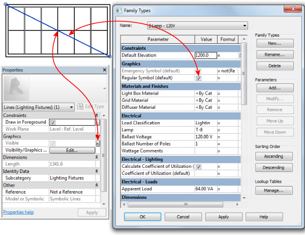
Figure 6.9 Yes/No parameter used in a family for visibility
Type Catalogs
Families can sometimes become crowded with many types. The number of type parameters used to define a family type potentially increases the number of family types. When these families are loaded into a project, all of the family types are loaded. This can quickly cause your project to be overloaded with unused family types. One way to remedy this scenario is to create type catalogs for families that contain many types.
A type catalog is a TXT file that contains values for the type parameters of a family. Having a type catalog associated with a family allows you to select only the family types you want to load when you insert the family into a project. You can create a type catalog for a family by creating a TXT file that has the same name as the family and is located in the same folder as the family file. Because type catalogs are TXT files in comma-delimited format, it is easier to edit them using a spreadsheet program such as Microsoft Excel.
To create a type catalog from scratch, start a new spreadsheet file. Enter all the family types in the first column of the spreadsheet. Each column after that will be a type parameter within the family. The type parameters must exist in the family file and have some value in order to be used in the type catalog.
In the past, you couldn't have instance parameters as part of a type catalog, but now that is possible as well. If you leave a parameter value blank in the family, the type catalog will ignore the parameter when the family is loaded. So, even though the parameters in the family are essentially placeholders for the type catalog, they need to have something input for their value. Figure 6.10 shows an example of a type catalog for a motor connection family.
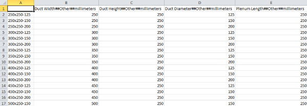
Figure 6.10 Sample type catalog
It is easy to see why a type catalog for this family is used; otherwise, all 15 family types would be loaded when this family is inserted into a project. Notice that the format for the type parameters is:
,parameter name##parameter type##units##
You can cheat with the parameter type a bit: Instead of remembering the proper formatting for all units, in most cases you can use Other.
Here are a few examples of proper formatting:
,Duct Width##HVAC_DUCT_SIZE##INCHES,Power##ELECTRICAL_POWER##WATTS,Air Flow##HVAC_AIR_FLOW##CUBIC_FEET_PER_MINUTE,Width##LENGTH##FEET
At first the formatting can be confusing, and if you don't have a cheat sheet, it will be hard to remember it for the various parameters. However, if you look closely, you are probably noticing a pattern; you can make sense out of all this instead of just trying to remember it. Let's take a look at the Duct Width parameter, for example. When you are creating this parameter, you need to select options for Discipline (HVAC), Type Of Parameter (Duct Size), Group Parameter Under, and whether it will be Instance or Type, as shown in Figure 6.11. Now look at the formatting for the preceding Duct Width parameter again. You can see that the syntax is as follows: <parameter name>##<Discipline_Type of Parameter>##units. OK, now this is a lot easier to understand and memorize than remembering about a 100 different configurations.
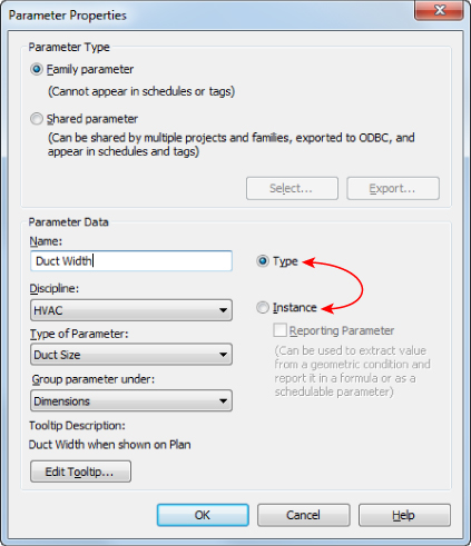
Figure 6.11 Parameter settings
You can create a type catalog by exporting parameters from a family. Note that this method is not available in versions of Revit from 2011 and earlier, so the previous method should be used. In more complex families containing a lot of parameters that don't need to be controlled via a type catalog, the previous method would still be more efficient. To create a type catalog by exporting parameters from a family, do the following:
- While in the family you want to create a type catalog for, choose Application
 Export Family Types. This exports the type parameters in a TXT file that you should save in the folder in which the family is located. This is the fastest way to create a type catalog; the downside is that it will contain all type parameters and in most cases you will need to clean it up a bit.
 - Create the spreadsheet and save it as a comma-separated values (CSV) file. If you receive a warning that some of the features of the file may not work when saved to CSV format, you can click Yes to save the file.
Once the file is saved, you can browse to it and rename the file with a
.txtextension to convert it. If you receive a warning that the file might become unusable when the filename extension is changed and asks if you want to proceed, click Yes.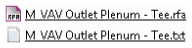
When a family with an associated type catalog is inserted into a project, a dialog box will appear that allows you to see the parameter values for each type and choose which family types you would like to load.
- Choose family types by selecting them from the list. You can select multiple types, as shown in Figure 6.12. You can filter the Specify Types dialog box based on specific parameter values by using the drop-down list under the heading of each column.
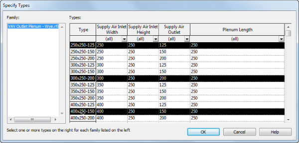
Figure 6.12 Specifying types from a type catalog
Formulas
Not all parameters in a family are used to drive the geometry directly; many are used to hold data that results from the creation of the geometry and that will be used for driving additional geometry or spatial relationships. This is done by creating a formula for a parameter. Formulas can vary in complexity and functionality, as shown in Figure 6.13. Pipe fittings are notorious for their complexity and the number of formulas they need in order to create the desired functionality.
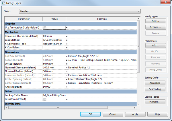
Figure 6.13 Formulas in fittings
One nice feature of formulas is that when you change a parameter name, it will be updated in all formulas where this parameter is used. Mathematical operators and Boolean functions can all be used. Placement of parentheses, proper units, case, parameter names, and context sensitivity are all important for your formulas to work properly. A warning will appear if the result of a formula does not match the units for a parameter or if a parameter name is misspelled.
Formulas can even be used for parameter types such as a Yes/No parameter. Figure 6.14 shows a Boolean formula used to determine when a check box should be selected for a Yes/No parameter. The formula indicates that the box is either deselected or selected when the conditions of the formula are true.
Figure 6.14 Boolean formula for a Yes/No parameter
Formulas using if statements are powerful for providing exact conditions and variations in parameter values based on other parameter values. The format for an if statement is as follows:
if(logical_test,value_if_true,value_if_false)The value_if_false result is the value given to the parameter when the condition is not met. You can use other parameters to define the condition. For example, if you want a Width parameter to equal the Length parameter under certain conditions, you could write this formula:
if(Length>2′ 0″, Length, 1′ 0″)
if(Length>600mm, Length, 300mm)
This formula would cause the Width value to equal the Length value when the Length is greater than 2′-0″ (600 mm); otherwise, the Width value would be 1′-0″ (300 mm).
System Parameters
When you create a family, certain parameters exist by default. These parameters are hard-coded into the software and cannot be removed. You can use these parameters to avoid having to create custom parameters.
These parameters vary depending on the category you choose for the family. The system parameters under the Identity Data group are common to component families and are also included in system families within a project.
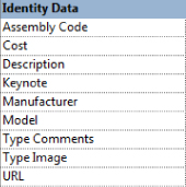
There are, however, a few that do not appear in the Family Types dialog box when you're working in the Family Editor but do appear in the Type Properties dialog box or the Properties palette after the family has been loaded into a project. The most notable of these are the Type Mark, Offset, Level, Host, Mark, Phase Created, and Phase Demolished parameters. The Type Mark parameter is often used to identify a component with a tag or in a schedule. Because this parameter does not exist in the family file, you cannot use it in a type catalog. One way to avoid creating a custom parameter that does essentially the same job as the Type Mark parameter is to have your type catalog create family types named with the same value you would use for the Type Mark. Then you can tag or schedule that type parameter instead of the Type Mark parameter. To appear in a schedule or a tag, the parameter has to be a shared parameter.
Lookup Tables
Lookup tables are designed to drive instance parameter values via an external CSV file. They are similar to type catalogs in that they store parameter values. But type catalogs are meant for type parameters (even though in recent versions of Revit MEP you can control instance parameters with them as well). Perhaps the main difference between type catalogs and lookup tables is that type catalogs are accessed by Revit MEP when you are loading a family, while lookup tables are loaded when the software launches and Revit MEP uses all of their data all the time. In addition, type catalogs must reside in the same folder as the family; lookup tables are located in a different location than the family. Lookup tables are mostly used for pipe, duct, conduit, and cable tray fittings. But they can be used for anything else that requires constant referencing. When you install Revit MEP 2015, an extensive library of lookup tables is installed that can be referenced by families.
Lookup tables are CSV files that work like a type catalog. They provide values for dimensions based on other dimensions within the family. The data in lookup tables can be driven by design codes or manufacturing standards to ensure the graphical accuracy of your components. Pipe fittings, for example, have a nominal diameter that is used to identify the size, but the actual outside diameter is slightly different, especially for different pipe materials. A lookup table can provide the outside diameter dimension for each nominal diameter that exists in the table.
Since Revit 2014, content creators have had the ability to embed lookup tables directly into the family. In fact, the majority of families that are installed by default already have lookup tables embedded. This greatly reduces the issue of having to ensure that the table travels with the family (within a project) not only when being issued to external sources but also when your IT department is reluctant to place additional files into your lookup table folders on a protected network drive or into folders distributed to each computer on the network. With the lookup table embedded into the family, you will always get a correctly sized family regardless of where that family is loaded.
The Lookup Table Name parameter is used to identify which CSV file the family is referencing. The location of your lookup tables is defined in your Revit.ini file. When you type in the name of a lookup table, you do not need to include the full path to the file, only the name and filename extension. As with parameter names, referencing a lookup table name is case and context sensitive.
Once you have referenced the lookup table with the Lookup Table Name parameter, you can access the data in the table by using a formula for the value of a parameter. The formula using lookup table data is as follows:
text_file_lookup(Lookup Table Name, ″Column Name″,
Value if not found in table, Value found in table)
The result of this formula will apply the value found in the table to the parameter, or it will apply the defined value given in the formula if none is found in the table. Figure 6.15 shows the formula used to determine the value of the Fitting Outside Diameter (FOD) parameter of a pipe-fitting family. The FOD column is searched for a value that coincides with the value given for the Nominal Diameter parameter, and that value is applied to the FOD parameter. If the Nominal Diameter value given in the family does not match one in the table, then Nominal Diameter + 1/8″ is used for the FOD.
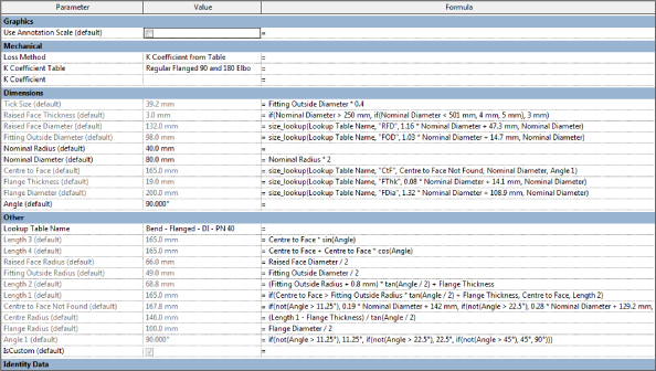
Figure 6.15 Lookup tables in formulas
For additional information on working with parameters in family files, another good reference point is the Autodesk Families Guide, which can be accessed from the Autodesk Help site:
Help ![]() Revit Users
Revit Users ![]() Build the Model
Build the Model ![]() Revit Families.
Revit Families.
Using Shared Parameters
Shared parameters are the most versatile parameters you can use, but they also require the most management. Used properly, shared parameters can help ensure that your schedules are coordinated and that your construction documents are reporting the correct information. Shared parameters can be type or instance parameters that are used in families or as project parameters. The main advantage to using shared parameters is that the data they hold can be exported or reported in tags and schedules.
Shared parameters are parameters that are created with their settings stored in a TXT file. It may help to think of this file as a library of parameters, similar to a library of model components.
When you need to add a parameter to a family or project, you can use one from your shared parameters file. This helps with the management of your content and project standards because you can be consistent in your use of parameters. It also helps with maintenance by allowing you to avoid duplication of parameters, which can cause coordination issues. Multiple parameters with the same name can show up as available for use in a schedule, and you will not be able to tell which one is the correct one to use.
You can create a shared parameter by doing the following:
- Click the Shared Parameters button on the Manage tab. When you create a parameter in the Family Editor or add a project parameter, you have the option for it to be a shared parameter. Selecting this option activates the Select button in the Parameter Properties dialog box.
- In the Edit Shared Parameters dialog box, you must first create a shared parameters file. Click the Create button to select a location for the file.
You can have multiple shared parameter files, so it is a good idea to create a folder in a common location that you and others can access. But keep in mind that having multiple shared parameter files is possibly asking for trouble because you have to manage each file, ensuring that no duplicates exist.
You can access these files by clicking the Browse button in the Edit Shared Parameters dialog box, which is shown in Figure 6.16.
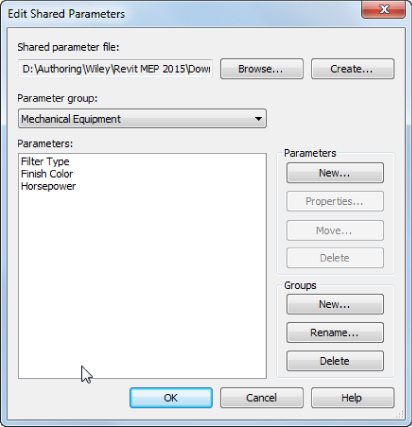
Figure 6.16 Edit Shared Parameters dialog box
There are two components to a shared parameters file. The parameter group is a level of organization that you can establish to group parameters together. This is not the same group as shown in the Parameter Properties dialog box for defining where parameters will be listed. These groups are available so that you can keep your shared parameters organized. One common method of organization is to create groups based on family categories. Figure 6.17 shows an example of parameter groups created for parameters that apply to specific family categories. This method is intuitive and could help you find the parameters you need for the family you are creating much faster. But there are many parameters that will be used across multiple families (Length, Air Flow, and so forth), and it could be confusing.
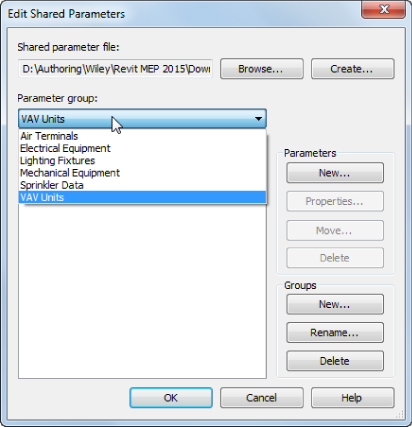
Figure 6.17 Method 1—using family categories
Notice that a group has been created for variable air volume (VAV) units. Although it is possible to create a group with any name, keep in mind that the parameters must be assigned to a category. In the case of these parameters, they will be applied to all mechanical equipment if they are used as project parameters, even though they are specifically designed for VAV units. The parameters in this group could be added to a lighting fixture family if chosen. Parameter groups can be renamed or deleted by using the buttons in the lower-right corner of the dialog box. You cannot delete a group until all parameters have been removed from it.
Another way to organize your shared parameter groups is to use the Group Parameter Under pull-down in the Parameter Properties dialog box. When you use this method, the position of the parameter grouping will be identical in both the shared parameters file and in the properties of the family, as shown in Figure 6.18. If you choose this method, don't hurry to create all of the groups exactly as they appear in the Parameter Properties dialog box. You will find that half of those groups are unnecessary, and you may never use them. So, create only what you need, and you can always add more as you find them necessary.
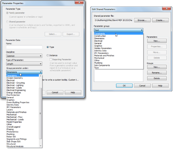
Figure 6.18 Method 2—using Group Parameter Under
- After you have established a group in your shared parameters file, you can begin to create parameters. Click the New button in the Parameters section of the Edit Shared Parameters dialog box to open a Parameter Properties dialog box. This is not the same dialog box that you get when you create a parameter in the Family Editor or in a project. This is a simple dialog box, because all you need to define for a shared parameter are the Name, Discipline, and Type Of Parameter settings, as shown in Figure 6.19. The parameter that you create will be added to whatever group you have active when you click the New button.
The Name, Discipline, and Type Of Parameter settings are the same options used for creating a family parameter.
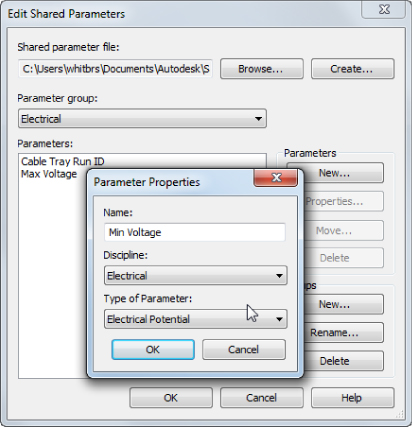
Figure 6.19 Parameter Properties dialog box for a shared parameter
- Once a parameter has been created, you can select it and click the Properties button to view its settings. The settings cannot be changed after a parameter has been created. If you want to change a shared parameter, you have to delete it and re-create it with the new settings. If you do so, you will have to add the parameter back to any object that had the parameter you're replacing.
- If you create the parameter in the wrong group, however, all is not lost. Simply select the parameter and click the Move button, which allows you to move the parameter to another group.
Choose and establish shared parameter settings very carefully. A parameter that is deleted from your shared parameters file will remain in families or projects—you will not be able to add it to anything new. There is a get-out clause here if you have deleted a shared parameter that you later wish to keep. Open any family or project where you know the parameter exists. Select the parameter in the Type Properties dialog box and click Modify. Once you're in the Parameter Properties dialog box, click the Export button. This exports the shared parameter to a parameter group called Exported Parameters in the shared parameters file, and the parameter can be moved if necessary, as described earlier.
You can add a shared parameter to a family by doing the following:
- Select the Shared Parameter option in the Parameter Properties dialog box. This activates the Select button, which opens the Shared Parameters dialog box.
- Choose the group that contains the desired parameter, and then select the parameter from the list.
- Once you click OK, you still need to define whether it will be a type or instance parameter and where it will be listed. These are the only two settings that can be modified after the parameter is added to the family.
- Click the Edit button in the Shared Parameters dialog box to open the Edit Shared Parameters dialog box, where you can browse to another shared parameters file or make changes to the active file.
- Once you exit this dialog box, you still need to select the parameter from the Shared Parameters dialog box to add it to the family. Once a shared parameter is added to a family, it can be used as a constraint or in formulas (just like any other parameter).
Managing shared parameters should be treated with the same importance as managing your content library. Because these parameters provide intelligence that carries through from a family all the way to your construction documents, it is important that they are maintained and used correctly. Preventing users from having full access to this file is one way of managing this, much in the same way as many libraries have restricted, read-only access.
One category for which shared parameters can become cumbersome is the Mechanical Equipment category. Typically, many characteristics of a mechanical unit are required to be scheduled, so shared parameters are necessary. Some of these characteristics are the same unit of measurement, but for a different component of the unit. Since you cannot add the same shared parameter to a family more than once, you may need to make multiple parameters of the same type. It is best to try to keep your shared parameters as simple as possible for this category. Naming parameters specifically for their use is helpful in keeping track of them. In addition, developing a standard for where these parameters are grouped in the families will help you avoid confusion when editing the properties of a family.
Even though it may initially require a bit of work, adding these parameters directly to your mechanical equipment families rather than as project parameters will go a long way in keeping your families from becoming overcrowded with unused parameters. Consider keeping a document such as a spreadsheet that lists all of your custom parameters and indicates whether they are family or project parameters, what parameter groups they exist in if they are shared parameters, where they are grouped in the properties of a family, and whether they are used as type or instance parameters. Having this document open will be helpful when creating new content, because you will know what parameters already exist and how to use them. As new parameters are created, the document can be updated. If you work in an environment with multiple users, it is best to keep only one copy of this document in a common location. You can organize the file and list the family in which the parameter is used or you can do it by schedule. Figure 6.20 demonstrates a sample Excel file that manages the shared parameters by schedules that they belong to.
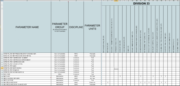
Figure 6.20 Sample Excel file organizing all shared parameters
Using Parameters in Projects
Parameters are typically handled at the component level for building objects, but there are also parameters for noncomponent objects such as views, sheets, and annotations. You may need to create custom parameters for system families that cannot be edited in the Family Editor. These parameters can be added to designated categories within your project so you can assign them to system families. Your projects themselves can have parameters that convey project-specific information. Understanding how to use parameters in a project is the key to getting the most benefit from constructing an intelligent model with computable data.
Project Parameters
The only way to add a parameter to a system family is to add it by creating a project parameter. This allows you to customize the information you want from elements within the model. Space objects can be given a lot of useful data to help make design decisions and to analyze the model performance. Project parameters make it possible to add this data to spaces and other elements that cannot be physically edited.
You can add a project parameter by clicking the Project Parameters button on the Manage tab. In the Project Parameters dialog box, you can see a list of any parameters that have been added to the project. Clicking the Add button opens the Parameter Properties dialog box, shown in Figure 6.21. This is the same dialog box as in the Family Editor but with additional settings to assign the parameter to an object category. The object category list includes all the component families, system families, in-place families, and even metadata that may not be physical geometry, such as views, sheets, project information, and so on.
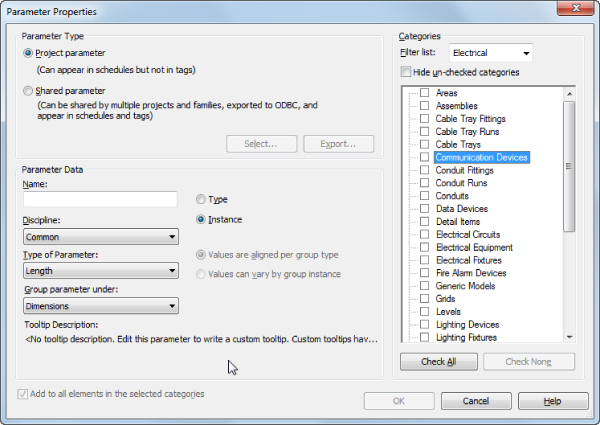
Figure 6.21 Parameter Properties dialog box for a project parameter
The settings for creating a parameter or adding a shared parameter are the same for project parameters. The only difference is the Categories section of the dialog box. This is where you can select the Revit category to which the project parameter you are creating or the shared parameter you are loading is applied in the project.
Project parameters are a great way to use shared parameters in families without having to edit each family individually. The check box in the lower-left corner indicates that the parameter will be added to all elements in the project that belong to the selected category. So, if there are parameters that you want to use on a particular category of elements, such as light fixtures, you can create the parameters as shared parameters and then load them as project parameters into your project template file. Then, whenever you load a family belonging to that category into your project, it will have the desired parameters, which can be used for scheduling or tagging.
Additionally in this dialog box are the radio buttons Values Are Aligned Per Group Type and Values Can Vary By Group Instance. They appear uneditable when Type Of Parameter is set to the default Length, but if you change it to Text, Area, Volume, Currency, or a few more, you will be able to switch between the two.
- Values Are Aligned Per Group Type (Default) If an element with this instance parameter is part of multiple groups, the parameter value will be the same for corresponding elements in all group instances. While in Edit Group mode, you can select the element and modify the parameter on the Properties palette. Changing the parameter value for the element in one group will change the value for the corresponding element in all other instances of the same group type.
- Values Can Vary By Group Instance If the element with this instance parameter is part of multiple groups, the parameter value can vary for corresponding elements in group instances. While in Edit Group mode, you can select the element and modify the parameter on the Properties palette. Changing the parameter value for the element in one group will not change the value for the corresponding element in other instances of the same group type.
If you change an existing parameter from Varies to Aligned, an error message appears, listing the elements with the parameter that will change. If you click Align Parameter Values, then all group instances will update to have the same parameter value. The value applied is the value that was assigned to the element in the first group instance.
When you add a parameter to your project and it is applied to elements in the chosen category, the parameter will not have a value. You can easily give the parameters values by creating a schedule of the elements and including the project parameters in the schedule.
Yes/No type parameters will be set to Yes (selected) by default and appear to be uneditable when they are viewed in a schedule or the properties of an element. You can click the grayed-out check box once to make it editable.
Parameters in Schedules
Family parameters and some system parameters cannot be used in schedules. If you do not want to use shared parameters in your families, you can create project parameters for scheduling information about components. In the Schedule Properties dialog box at the center of the Fields tab is an Add Parameter button, as shown in Figure 6.22. Clicking this button opens the Parameter Properties dialog box; this is the same dialog box that you get when you click Project Parameters. Essentially, you can create project parameters from the Project Parameters dialog box or from a schedule. All of them will appear in the Project Parameters list. However, there is a difference depending on whether you create them from the dialog box or from a schedule. When you create the parameters from a schedule, they will automatically be applied to the category of the schedule. For example, if you are scheduling mechanical equipment, creating a parameter in that schedule will automatically apply it to all mechanical equipment. But what if you want the same parameter to apply to other object categories as well? You can do this from the Project Parameters dialog box, where you will be given the opportunity to select any additional categories. As we mentioned in the beginning of this chapter, project parameters can appear in schedules but not in tags (see Figure 6.23).
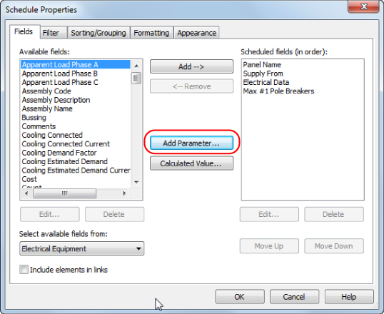
Figure 6.22 Schedule Properties dialog box for adding parameters
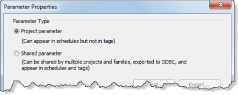
Figure 6.23 Parameter Properties dialog box
Using the Calculated Value feature of a Revit schedule will create a parameter to hold the value, but this parameter is not added to the properties of elements or the Project Parameters list. It appears only in the schedule where it was created and nowhere else.
Whether they are shared parameters or not, project parameters are required for scheduling system families such as duct, pipe, or cable tray. It is easiest to create these parameters when you are building the schedule for such elements. Once the parameter is created, you can access it from the Project Parameters button on the Manage tab to add it to other categories or make any necessary changes. Creating these parameters in schedules within your project template will ensure that they are consistently used from project to project.
One useful type of project parameter to create is for the schedule type of an element. This parameter can be applied to any category that is scheduled, and it is useful for filtering your schedules. Some people may prefer to create this parameter as a project parameter, which is easier and faster. We recommend creating it as a shared parameter and including it in all your families with a predefined value. This way, as you load boilers, chillers, AHUs, and so on, they will automatically be displayed on the appropriate schedules, assuming you have given them the appropriate value for the parameter and the schedule is using that as a filter.
Creating and Using Parameters in Families and Schedules
Understanding how to use parameters to get the information you require is the key to successfully reaping the benefits of Revit. Knowing where and when to use certain types of parameters will make it easy for you to manage the data within your Revit projects.
- Download the
Ch6_Project.rvtandCh6 Shared Parameters.txtfiles found at www.sybex.com/go/masteringrevitmep2015. - Open the
Ch6_Project.rvtfile. Open the VAV Schedule view. Access the Fields tab of the Schedule Properties dialog box, and click the Add Parameter button. - Create a project parameter called Schedule Type with the following settings:
- Instance
- Discipline: Common
- Type Of Parameter: Text
- Group: Identity Data
- Click OK to exit the Schedule Properties dialog box. For each VAV listed in the schedule, enter a value of VAV for the Schedule Type parameter.
- Access the Filter tab of the Schedule Properties dialog box.
Set Filter By to Schedule Type, Equals, and VAV, as shown in the following dialog box:
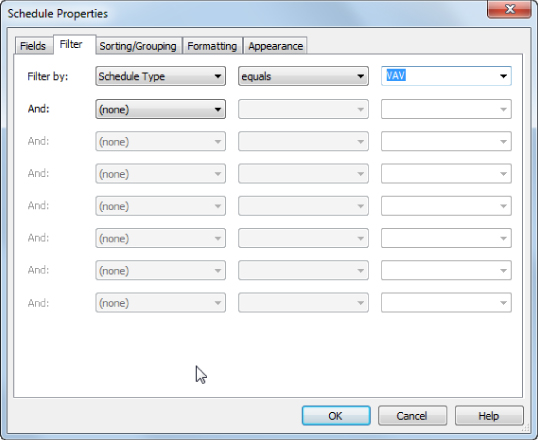
- Click OK to exit the Schedule Properties dialog box. Notice that now only the VAVs are listed in the schedule. Click the Project Parameters button on the Manage tab of the ribbon. Notice that the Schedule Type parameter is now a project parameter that will be added to any mechanical equipment loaded into the project. Exit the Project Parameters dialog box.
- Open the 1 – Lighting ceiling plan view. Click one of the light fixtures in the view, and click the Edit Type button in the Properties palette. Notice the Ballast Voltage parameter in the Electrical group. Click OK to exit the Type Properties dialog box.
- Open the Lighting Fixture Schedule view. Access the Fields tab of the Schedule Properties dialog box. Notice that the Ballast Voltage parameter that exists in the lighting fixture family is not listed in the Available Fields list because it is a family parameter.
- Click the Add Parameter button on the Fields tab of the Schedule Properties dialog box.
- In the Parameter Properties dialog box, select the Shared Parameter option and click the Select button.
- Click the Edit button in the Shared Parameters dialog box. Click the Browse button in the Edit Shared Parameters dialog box, and browse to the downloaded
Ch6 Shared Parameters.txtfile location. (Note that if you have never selected a shared parameters file, you will be asked to select one. Browse to the location of the downloaded file.) - Set Parameter Group to Lighting Fixtures. Click the New button under Parameters on the right side of the dialog box.
- Create a new parameter named Fixture Voltage. Set Discipline to Electrical. Set Type Of Parameter to Electrical Potential. Click OK to exit the Parameter Properties dialog box. Click OK to exit the Edit Shared Parameters dialog box.
- In the Shared Parameters dialog box, set the parameter group to Lighting Fixtures. Select the Fixture Voltage parameter from the list, and click OK to exit the Shared Parameters dialog box.
- In the Parameter Properties dialog box, select the check box in the lower-left corner to add the parameter to all elements in the category. Set the parameter as a type parameter, and click OK to exit the dialog box.
- Notice that the Fixture Voltage parameter is now in the Lighting Fixture schedule. You can now input values for voltage into the parameter.
View and Sheet Parameters
Views and sheets are system families, so you need to use project parameters to include additional information or functionality in them. This type of information may be necessary for construction documentation or simply for organizing your project for more efficient workflow. Depending on their use, these parameters may need to be shared parameters.
One of the more common parameters for views is the Sub-Discipline parameter. This parameter allows you to assign a subdiscipline value to the properties of any view to establish a secondary level of organization within the Project Browser. This parameter is already established in the default template files provided with Revit MEP 2015. For more information on using this parameter and other alternatives for Project Browser organization, refer to Chapter 2, “Creating an Effective Project Template.” Much of the information that appears on a sheet border is common to every sheet. If the parameters that hold this information were unique to each sheet, it would be time-consuming to make certain changes. Project parameters that are applied to the Project Information category can be included in your titleblock so that the value can be changed in one location and globally updated to all sheets.
One example is for total sheet count. Including this information on a sheet as an editable parameter would require creating a shared parameter. A label of this parameter could then be placed within the titleblock family. The shared parameter could then be added as a project parameter applied to the Project Information category, as shown in Figure 6.24.
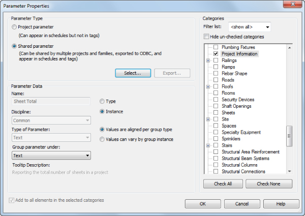
Figure 6.24 Project parameter for sheet total
Notice that the parameter is an instance parameter. You cannot create type parameters for the Project Information, Sheet, or View categories. However, since there is only one instance of Project Information in a project, essentially those instance parameters behave like type parameters. For example, say you create an instance project parameter called Building No. and apply it to Project Information. Even though it is an instance parameter, it is global for the project because there is only one instance of it. Instance parameters for views and sheets behave like normal instance parameters.
When the project information is edited, the value will be updated on every sheet in the project. Figure 6.25 shows this example on a titleblock in a sample project.
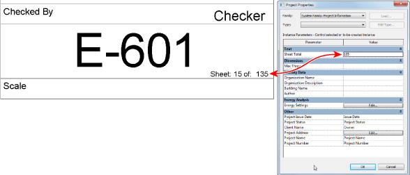
Figure 6.25 Shared parameter used on a sheet
Combining the power of shared and project parameters can give you the ability to report, tag, or schedule any data within your model or about your project in general. Once you understand how to use parameters effectively, the real work becomes managing them for consistency and accuracy within your projects.
Working with Formulas
Formulas let you create some truly intelligent families and in most cases can increase your designers' efficiency by automating certain tasks. Working with formulas in Revit has its own challenges that you need to be aware of. They are case sensitive, they are “aware” of units, and they won't work properly if your parameters use mathematical symbols (/ * – +) in their naming convention. Table 6.1 lists basic operators used in formulas. Table 6.2 gives a list of conditional statements used in formulas.
Table 6.1 Basic operators
+ |
Add: Length + Width | abs |
Absolute Value: abs (–5) will return 5 |
- |
Subtract: Length – Connector Protrusion | pi |
Pi: pi() * (Radius ∧ 2)—the circumference formula |
* |
Multiply: Width * Length | sin |
Sine: sin (45) |
/ |
Divide: Height/Length | cos |
Cosine: cos (45) |
∧ |
Exponent: Length∧3 | tan |
Tangent: tan (45) |
log |
Logarithm: log (100) | asin |
Arcsine: asin (45) |
sqrt |
Square root: sqrt (49) | acos |
Arccosine: acos (45) |
exp(x) |
E raised to an x power: exp (2) | atan |
Arctangent: atan (45) |
< |
Less than | ||
> |
Greater than |
Table 6.2 Conditional statements
if |
if statement |
and |
Both statements are true |
or |
One of the statements is true |
not |
The statement is false |
Sample Conditional Statements
Conditional statements are a very powerful way of controlling the behavior of your Revit families. For the most part, conditional statements work exactly the same way they do in Excel or any other program that supports them. Here are few examples for the most common conditional statements:
- Simple
ifStatementsif(Neck Size<10″,16″,18″)if(Neck Size<250mm, 400mm, 450mm) - Formula That Returns Strings
if(Neck Size>10″,″Neck Size is too Big “Neck Size is Correct”)if(Neck Size>250mm,″Neck Size is too Big “Neck Size is Correct”)
The next two types of statements (Logical and/or) are good for testing whether a diffuser has been sized correctly. Either of the following formulas could be used:
- Using Logical
andIf(and(Air Flow>Minimum Air Flow, Air Flow<Maximum Air Flow),“Correct”, “Wrong Size”) - Using Logical
orIf(or(Air Flow<Minimum Air Flow, Air Flow>Maximum Air Flow),“Wrong Size”, “Correct”)
Both of the preceding statements give the result—a text string—stating whether a connection is correctly sized…or not.
- Using Logical
notif(not(Top Alignment), 0″, tan(15$) * b) - Using Logical
notfor Yes/No Parametersnot(myCheckbox) - Using
ifwith Yes/No ConditionIf (Length>10)(Note that both the condition and the results are implied.)
- Embedded
ifStatement with Logicalandif(and(Maximum Air Flow < 391 CFM, Auto Size), 8″, if(and(Maximum Air Flow < 641 CFM, Auto Size), 10″, if(and(Maximum Air Flow < 1001 CFM, Auto Size), 12 1/2″, if(and(Maximum Air Flow < 1651 CFM, Auto Size), 15″, if(and(Maximum Air Flow < 2201 CFM, Auto Size), 17 1/2″, if(and(Maximum Air Flow < 3001 CFM, Auto Size), 18″, OVERRIDE HEIGHT)))))if(and(Maximum Air Flow < 185 l/s, Auto Size), 200mm, if(and(Maximum Air Flow < 300 l/s, Auto Size), 250mm, if(and(Maximum Air Flow < 470 l/s, Auto Size), 350mm, if(and(Maximum Air Flow < 780 l/s, Auto Size), 400mm, if(and(Maximum Air Flow < 1000 l/s, Auto Size), 450mm, if(and(Maximum Air Flow < 1400 l/s, Auto Size), 450mm″, OVERRIDE HEIGHT)))))
Revit can be very picky about the units that you use in formulas. For example, you can't use the Number parameter in a CFM (l/s) parameter unless you do some sort of conversion. In most but not all cases, simply multiplying or dividing by 1 does the trick.
Rounding
Prior to Revit 2012, there were two options for rounding numbers: running them through an integer parameter (which automatically rounds them up) or adding 0.49 to the formula. In most formulas, the rounding needs to be to the next higher whole number, even if the number isn't higher than 0.5, such as for the occupancy of people. If the number is 2.4, it really needs to be 3. For example, 2.4 + 0.49 = 2.89, which will be rounded to 3.
As of Revit 2012, we have three additional functions to use: Round(x), Roundup(x), and Rounddown(x). Note that x is unit-less (also known as a number, not CFM, not GPM, and so on). The Round(x) function rounds to the nearest whole number:
round (1.2) = 1
round (1.5) = 2
round (1.7) = 2

round (-1.2) = 1
round (-1.5) = 1
round (-1.7) = 2
The Roundup(x) function rounds to the largest whole number greater than or equal to x, such as in the following example:
round (1.0) = 1
round (1.4) = 2
round (1.6) = 2

round (-1.0) = -1
round (-1.4) = -1
round (-1.6) = -1
The Rounddown(x) function rounds to the smallest whole number less than or equal to x, as in this example:
round (1.0) = 1
round (1.4) = 1
round (1.6) = 1

round (-1.0) = -1
round (-1.4) = -2
round (-1.6) = -2
The Bottom Line
- Manipulate the properties of parameters The parameters used to define the properties of elements have properties of their own that define their behavior and how they can be used.
- Master It It is important to know when and where parameters can be used for extracting data from a model or project. It is also important to understand how instance and type parameters are used. Describe how the use of instance and type parameters affects the way data is changed in a family.
- Work with type catalogs Type catalogs are powerful tools that allow you to load only what you need for a specific project.
- Master It Certain families can have multiple family types. If a family has many types, all of them will be loaded into a project when the family is loaded. What can be done to limit the number of family types that are loaded when a family is inserted into a project?
- Work with shared parameters Shared parameters are useful because they can be used in schedules and in annotation tags. Shared parameters can be applied directly to families or added as project parameters.
- Master It Managing shared parameters is as important as managing your component libraries. Explain the importance of keeping a common shared parameters file for multiuser environments.
- Use parameters in project files The use of parameters is not limited to component families. Parameters can be added to any element that makes up a Revit project.
- Master It You can add parameters to system families only by creating project parameters. When you create a project parameter, it will be added to all the elements in the chosen category. Explain why managing project parameters is important to using them in schedules within a project.