
![]()
Calibrating the Printer
The most important aspect of setting up your printer for the first time is calibrating the mechanisms to produce the correct movement in all three axes and the accurate extrusion of filament. Failing to do this or rushing through this process can result in a number of issues with your printer. Some of these may not be obvious until you print a very large object or even an object with sufficient detail, such as overhang or gap coverage.
Calibration-related inaccuracies can be subtle and thus almost undetectable. They can also become serious and affect the quality of your prints. Significant inaccuracies can result in a wide range of problems, including inaccurate object size (too large, too small), excess filament (resulting in globs of filament), insufficient filament (weak layer bonds), and adhesion problems. I’ve read a number of articles and requests for help, and heard general misery from people who have struggled with one or more of these maladies. More often than not, the owner is treating the symptoms rather than the source of the problem. Proper calibration won’t solve all of your printing woes, but it will go a long way toward improving your experience and the quality of your prints.
This chapter is therefore an effort to help you avoid the worst of these calibration-related problems by introducing a step-wise procedure for setting the endstops, calibrating each of the axes and the extruder, and leveling (tramming) the print bed. Once all of these elements are working like they are supposed to, you can then turn your attention to fine-tuning your print files for even better, faster printing. But let’s get that printer dialed-in mechanically first!
Setting the Endstops
Recall that endstops are used to set either the minimum or maximum travel of the axis. They are mounted so that a physical part of the axis movement forces the endstop to close, thereby triggering the firmware that the axis has reached a specific point in its movement.
The mount for the endstop should be either a clamp that can be tightened or a press-fit arrangement that permits the endstop to be mounted in a stationary position. Endstops that can be moved easily (say, by sliding along one of the smooth rods) can cause a host of issues, not the least of which is inconsistent homing. Check each of your endstops to ensure that they cannot be moved easily. As mentioned, press-fit is fine provided it is a very firm fit that cannot be moved when triggered.
In previous chapters, I discussed setting the endstops in a general location far enough from the hard bits to avoid a crash. In this section, we examine setting the endstops to the proper location by fine-tuning their position on the axis.
![]() Note I am referring to mechanical endstops in this section. There are also optical and hall-effect endstops. Optical endstops use a special sensor to detect when an obstruction passes through two points. Hall-effect endstops detect the proximity of a magnet. These other endstop types achieve the same goal but have different signaling mechanisms.
Note I am referring to mechanical endstops in this section. There are also optical and hall-effect endstops. Optical endstops use a special sensor to detect when an obstruction passes through two points. Hall-effect endstops detect the proximity of a magnet. These other endstop types achieve the same goal but have different signaling mechanisms.
The X-axis endstop should be set so that the X carriage (that holds the extruder and hot end) arrests its movement prior to the nozzle leaving the print bed surface or prior to the nozzle striking any clips or fasteners on the print bed.
The most common location for this endstop (for single extruder machines) is on one of the smooth rods for the X axis. Figure 5-1 shows the X-axis endstop for a Prusa i2 printer. Notice how the endstop is oriented so that the X carriage itself is used to close the switch. Notice also that it is held in place with a clamp that doubles as the endstop holder.

Figure 5-1. X-axis endstop location Prusa i2
![]() Note Printers with multiple extruders offset on the X axis will be set up so that the rightmost nozzle can travel to the edge of the print surface.
Note Printers with multiple extruders offset on the X axis will be set up so that the rightmost nozzle can travel to the edge of the print surface.
The X-axis endstop for a Prusa i3 is similar, as shown in Figure 5-2.

Figure 5-2. X-axis endstop location Prusa i3
The endstop holder in this example is mounted using a press-fit mount. In this case, the endstop can be moved by hand, but the force of the extruder closing the switch does affect the location of the mount.
You may also notice that the Prusa i3 is using an endstop with four wires instead of two. This is because these are endstops modeled after the MakerBot version 1.2 endstop. The endstop includes an LED that illuminates when the switch is closed. This requires two additional wires to power the LED. Actually, it uses a common ground between the center pins, which means you can connect only three wires to use this endstop: ground, positive 5v, and signal for the endstop.
To adjust the endstop, power off your printer first.1 Then, slowly move the X carriage until you hear the switch close. You should be able to hear an audible click.
![]() Caution When manually moving axes, always move them very slowly so as not to generate current that will feed back to your electronics. Alternatively, you can disconnect the stepper motor during the move, but remember to plug it back in while the printer is turned off.
Caution When manually moving axes, always move them very slowly so as not to generate current that will feed back to your electronics. Alternatively, you can disconnect the stepper motor during the move, but remember to plug it back in while the printer is turned off.
Next, observe where the nozzle is in relation to the print bed. Does it appear that the nozzle tip is clear of any obstructions, such as binder clips or similar on the print bed surface? Similarly, is the nozzle located within the dimensions of the heated print bed (if equipped)? If you need to change the position of the endstop, move the axis away from the endstop and reposition it. Repeat the process until the nozzle stops inside all obstructions, as well as inside the heat zone for the print bed. Figure 5-3 shows an example of the correct location for a Prusa i3 X-axis endstop.

Figure 5-3. Correct X-axis endstop location for a Prusa i3
Y-Axis Endstop
The Y-axis endstop should be set so that the print bed arrests its movement prior to the nozzle leaving the print bed surface or prior to the nozzle striking any clips or fasteners on the print bed.
The most common location for the Y-axis endstop is under the print bed at the rear of the Y-axis mechanism. Sometimes you will see endstops mounted on the smooth rods; other times they are mounted on the threaded rods or similar frame components. Figure 5-4 shows the Y-axis endstop for a Prusa i2 and Figure 5-5 shows the Y-axis endstop for Prusa i3.

Figure 5-4. Y-axis endstop location Prusa i2

Figure 5-5. Y-axis endstop location Prusa i3
![]() Note The view for Figure 5-5 is taken from above. The arrows show the location of the endstop.
Note The view for Figure 5-5 is taken from above. The arrows show the location of the endstop.
In each of these examples, the endstop is oriented so that the bearing or bearing holder is used to close the switch. This means the endstop must be mounted so that the print bed can pass over the endstop. You may see other orientations that place the Y-axis endstop such that the print bed itself is used to close the switch. For example, a variant of the Prusa i3 Y motor mount has a mounting point for the Y-axis endstop.
Adjusting this endstop is the same procedure used for the X axis—only in this case, we are concerned about how far the print bed itself can move. Again, move the print bed slowly until it closes the endstop (listen for the click). Adjust the endstop so that the nozzle remains in the heat zone but does not come into contact with any obstructions like binder clips. Figure 5-6 shows the proper orientation of the Y-axis endstop with respect to the location of the nozzle over the print bed.

Figure 5-6. Correct Y-axis endstop location Prusa i3
HEAT ZONE
Most heated print beds have a colored line drawn around the border. This is more than simple border dressing. It demarcates the outer perimeter of the heated surface. That’s right, most heated build plates do not heat all the way to the edge. Keep this in mind when setting your X- and Y-axes endstops.
Z-Axis Endstop
The Z-axis endstop should be set so that the Z carriage (that also moves the X-axis mechanism) arrests its movement prior to the nozzle touching the print bed surface.
The most common location for this endstop is on the smooth rod on either the left or right side of the Z axis. Typically, you will find the endstop mounted loosely so that it can be more easily adjusted. More recent incarnations of RepRap printers use an endstop with a fine adjustment that allows you to alter the location in small increments. This allows you to set the Z-height quickly.
While it is true that the Z-axis endstop is just another switch and works the same way as the endstops on the other axes, there is a bit more to it than that. Unlike the X and Y axes, whose location does not affect print quality (only starting location), the Z-axis endstop is used to set the initial height of the first layer. If the endstop is set too high, the filament may not stick to the build surface, causing low adhesion for the first layer (and a maddening array of adhesion maladies). If the endstop is set too low, it can cause the first layers to appear “squished,” and if set low enough, can cause filament extrusion failures from obstruction (filament extrusion is blocked by build surface).
Let us take a moment to examine the types of Z-axis adjusters available and to discuss the correct Z-height for the first layer.
Unlike the X and Y axes, you are likely to need to adjust the Z axis periodically. Most people do this before they use the printer for the first time each day. Having to adjust one axis may seem odd, but there are several reasons for this.
Chief among these are the effects of humidity on build platforms that use a wood base. The wood can expand and contract, depending on the humidity. While typically this is only a very small amount, if you consider the proper Z-height is about 0.1mm, it doesn’t take much to throw that gap off.
Another possibility concerns changes induced by the application of different adhesion techniques. For example, blue painter’s tape is not the same thickness as Kapton tape. If you use another technique such as ABS slurry, the Z-height can be uneven across the build surface.
No matter the reason, you will have to make fine adjustments to the Z-height. Early RepRap printers, and indeed many early commercial printers, used a fixed endstop for the Z axis. Adjusting the Z-height means loosening the endstop mount and moving it slightly up or down, and then testing the height and repeating the process until you get the Z-height set. This is very error-prone and can take some practice to master. But there is a better way.
One of the first modifications most people make to their RepRap printers is to change the fixed endstop mount for the Z axis to an adjustable mount. There are many versions of Z-axis adjusters on Thingiverse. Some are better than others, and it really doesn’t matter how they work—provided they are not prone to loosening from vibration, and provide an even, linear movement, and can allow for fine adjustment (I’ve seen some that have preset detents that seem to never be quiet right). I will show you an example of a Z-axis adjuster in Figure 5-7.

Figure 5-7. Z-axis endstop location Prusa i2 with fine adjuster
Proper Z-Height
One of the challenges for a beginning 3D printer enthusiast is setting the proper Z-height. No matter what class of printer you are working with, there will be a mechanism you can use to set the Z-height. On older printers or printers that have not been upgraded, you may need to loosen and move the entire endstop mount. This is very error-prone. If you have this setup, you should consider getting a Z-axis adjuster to replace the endstop mount.
So what is the correct Z-height? The easiest and simplest method of setting the Z-height is using a sheet of paper. Most common weight paper is about 0.01mm thick. Thus, you use a piece of paper as a gauge to set your Z-height by positioning the Z axis to its lowest point and sliding the paper under the nozzle. If the paper slides under easily, lower the Z-axis endstop a very tiny amount and try homing the Z axis again. Repeat the process until the paper is very slightly gripped by the nozzle (between the nozzle and the print bed).
![]() Tip Make sure there is no filament protruding from the nozzle. Use a hobby knife to cut away the filament so that you are measuring the distance from the nozzle to the print bed.
Tip Make sure there is no filament protruding from the nozzle. Use a hobby knife to cut away the filament so that you are measuring the distance from the nozzle to the print bed.
You may also find that heating the print bed and the nozzle to their proper temperature may permit you to make more accurate measurements. Again, this has to do with what materials are used in the print bed and hot end. Some materials expand more than others when heated.
Z-Axis Endstop Location
Typically, the Z-axis endstop is located on the left side of the printer and mounted to the smooth rod underneath the X-axis mechanism (called the X-ends). The X-axis motor is normally mounted on the same side. Figure 5-7 shows the Z-axis endstop for a Prusa i2. Notice that the endstop is mounted on a fine adjuster assembly.
The adjuster used in the photo is a customized version of thingiverse.com/thing:16380. More specifically, it is mounted so that the arm is to the left, allowing the X-axis stepper motor to act as a mount point for the tall foot that activates the endstop. In this case, the adjuster moves the endstop itself. The use of a fine threaded bolt and nylon lock nut permits very fine adjustment, as well as not being affected by vibrations (it won’t come loose).
There are also a number of options for mounting the Z-axis endstop on a Prusa i3. One of the more popular methods is modifying the left X-end to include a long M3 bolt, which is used to trigger a fixed endstop. If you already have your X-ends printed, you can print a small bracket to hold the 3mm bolt. A spring and a nylon lock nut are used to both keep tension and reduce risk of changes due to vibration.
Like the Prusa i2, the endstop on the Prusa i3 is mounted on the left smooth rod. Depending on what type of Z-axis threaded rod clamp you use, you may need to use a narrow endstop mount. Notice that the LED is on in the figure. This indicates that the endstop is triggered, which can be really handy when adjusting the Z-height.

Figure 5-8. Z-axis endstop location Prusa i3
I have mentioned some RepRap enthusiasts are adopting auto Z-probing (sometimes inaccurately described as auto bed leveling). Auto Z-probing is a solution for automatically setting the Z-height, as well as compensating for uneven print beds. The most common mechanism uses a servo with the endstop mounted on a short arm. When the firmware’s auto Z-probing code is triggered, it deploys the servo arm to lower the endstop and performs probing (lowers the Z axis until the switch engages) at several points across the print bed. The arm is retracted once the Z-height is determined. Figure 5-9 shows one example of how the Z-axis endstop can be mounted on a servo with a short arm. In this photo, the endstop is deployed for probing. The endstop is normally rotated away from the heat bed.
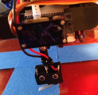
Figure 5-9. Z-axis endstop location Prusa i3 with auto bed leveling
While this sounds like a dream solution (especially if you’ve been setting your Z-height manually for a long time), you should know this is not a simple modification. It requires firmware changes, as well as additional hardware and a fairly tedious set-up procedure. I will discuss this feature and how to add it to your RepRap printer in more detail in a later chapter.
Calibrating the Stepper Drivers
There is one thing that you should do before you attempt to calibrate your axes. You should check the stepper drivers to make sure they are sending the right voltage to your stepper motors. It is OK if you haven’t done this step yet, but I highly recommended that you do it again as a double check.
The following presents procedures for setting A4988 stepper drivers. There are other stepper driver boards available. While the basic logical process is the same, the actual steps may differ for other boards. You should check your vendor’s web site for the correct procedure if you are using non-A4988-based stepper drivers.
First, check your stepper motor specifications to see what operating amperage the vendor recommends. You should be able to find this on the data sheet for the stepper motor. Next, check your stepper drivers to see what value resistors are used. For example, Pololu stepper drivers normally have 0.05 ohm resistors (but you need to check your vendor’s data sheet to know for certain). Finally, you can plug this data into the following formula to calculate the reference voltage (VREF).
VREF = Max_Amps * 8 * Resistors
For Pololu stepper drivers, the formula is:
VREF = Max_Amps * 8 * 0.05
Let’s suppose your stepper motors are rated at 1.0 amps. The reference voltage should be:
0.4V = 1.0 * 8 * 0.05
To measure the VREF, power on your printer and locate the small potentiometer on the stepper driver. Figure 5-10 shows a Pololu stepper driver. I have highlighted the potentiometer with an oval and the ground pin with a square.

Figure 5-10. Stepstick stepper driver module
To measure the voltage, use a multimeter set to measure DC voltage. If your multimeter has several settings, choose the one that measures up to 10 or 20 volts. Power on your printer and carefully place the positive probe on the center of the potentiometer and the ground probe on the ground pin. Read the voltage and compare it to your calculations.
If you need to increase the voltage, use a ceramic screwdriver to rotate the potentiometer clockwise a small fraction at a time. It only takes a small movement to increase or decrease the voltage. Measure the voltage again and repeat the process until you get the correct voltage. If you turn the potentiometer too far, you may cycle back around to 0 volts. Just keep turning the potentiometer, but do so using smaller increments. Repeat the process for each of your axes and the extruder printer driver.
![]() Caution Be careful where you put that probe! If you are using a RAMPS setup, the X-, Y-, and Z- stepper drivers are placed side by side. It is easy to accidentally touch the wrong pin. If you do, you may see a small spark, and if you are really lucky you won’t damage your stepper driver.2
Caution Be careful where you put that probe! If you are using a RAMPS setup, the X-, Y-, and Z- stepper drivers are placed side by side. It is easy to accidentally touch the wrong pin. If you do, you may see a small spark, and if you are really lucky you won’t damage your stepper driver.2
Now that the stepper drivers are calibrated, we can work on getting the axes calibrated properly. I discuss procedures for adjusting all three axes in the next section.
The next step in the calibration process is adjusting each axis so that movement is accurate. The basic process involves choosing a starting point (typically the home location if the endstops are set correctly), marking the location of the nozzle, measuring a predetermined distance out and marking that location, and then moving the axis a distance and measuring the actual distance traveled. The process is repeated using several starting locations and lengths.
If differences are found, you should check your calculations. If they are correct, and the axis movement is assembled correctly, you should not have to make adjustments. However, those axes that use toothless belts and similar mechanisms may require manual calibration. This is true for the extruder mechanism, but is not true for a threaded rod mechanism.
To calibrate non-mathematically predictable axes mechanisms, you would calculate the difference so that you can modify the firmware settings accordingly. For example, if the axis moves only 90% of the distance, you can adjust the firmware setting using a ratio to increase the steps per millimeter.
![]() Caution Axes calibration requires a stable chassis that has been assembled correctly. If your frame is loose or has parts that can come loose or oscillate, you can expect accuracy to suffer. Similarly, if the frame is out of square, it can cause odd behavior. Thus, before calibrating your axes, ensure that your frame is correctly assembled and true. See the “Frame and Chassis” section for tips on checking your frame.
Caution Axes calibration requires a stable chassis that has been assembled correctly. If your frame is loose or has parts that can come loose or oscillate, you can expect accuracy to suffer. Similarly, if the frame is out of square, it can cause odd behavior. Thus, before calibrating your axes, ensure that your frame is correctly assembled and true. See the “Frame and Chassis” section for tips on checking your frame.
However, before I get into the specifics of each axis, I will discuss the tools you will need so that you can have them ready when you perform the calibration.
Tools Required
The tools you need include any wrenches that fit the bolts securing your axis mechanism. Depending on the hardware used in your printer, you may need a screwdriver, hex key, and so forth, to loosen and tighten the components. If the axis is belt-driven, you may also need wrenches to tighten the belt tensioner. Check each axis prior to attempting the calibration steps to make sure you have the right tools at hand.
You will also need masking or blue painter’s tape and a pen or pencil. If you use blue painter’s tape, choose a fine point pen of contrasting color (e.g., black) so that it shows up well on the tape. You will be making marks on the tape to measure movement of the axis. Thus, a fine point will make measuring easier and a bit more accurate than a typical wide-tip permanent marker. Of course, a metric ruler is also required. Choose a shorter one (say, 100mm–150mm) for measuring lengths in confined spaces and a longer one (say, 300mm) for measuring the range of the axis. You may also find a digital caliper helpful when measuring the Z-axis travel.
In summary, you will need one or more of the following tools. Check your printer for the proper sizes of screwdrivers, wrenches, and hex keys.
- Wrenches
- Hex keys
- Screwdriver
- Ruler
- Digital caliper
Remember to update your firmware files (e.g., the Configure.h file in Marlin) with the new values. I like to annotate the code so that I capture the original values. The following shows an example.
// Refined settings. E steps was 524, now 552.5
#define DEFAULT_AXIS_STEPS_PER_UNIT   {100.00,100.00,4000.00,552.5}
X Axis
Let’s start with the X axis. Place a strip of blue painter’s tape or masking tape on the print bed. The tape should extend from one edge of the print bed to the other. Power the printer on (if not already) and home the X axis with either your printer controller software or the LCD menu on the printer. Once homed, move the axis out about 20mm. This should place the hot end well within the edge of the print bed.
![]() Tip I find it easier to use the printer controller software when calibrating. Sometimes the sensitivity of the rotary switch can cause you to move the axis too far or too little, which is annoying. It is better to use presets in the printer controller software or even use the G0 code to move the axis. For example, G0 X50 moves the X axis to position 50.
Tip I find it easier to use the printer controller software when calibrating. Sometimes the sensitivity of the rotary switch can cause you to move the axis too far or too little, which is annoying. It is better to use presets in the printer controller software or even use the G0 code to move the axis. For example, G0 X50 moves the X axis to position 50.
Next, you should lower the Z axis so that the nozzle is within about 5mm–10mm of the print bed. Use either the nozzle tip or the edge of the heater block to make a mark on the tape. This will be your starting point. Next, measure exactly 100mm to the right along the X axis and make another mark. Figure 5-11 shows how to mark the print bed.

Figure 5-11. Measuring the X-axis movement
Now move the X axis exactly 100mm using your printer controller software or the LCD menu. Observe the mark you made at 100mm. Did the edge you used to measure the starting point stop at the 100mm mark? If so, try moving the axis back about 50mm or 75mm, and make a second mark, and then measure another 100mm and try the movement again. Figure 5-12 shows an example of the X axis moving correctly to the 100mm mark on the print bed.

Figure 5-12. Accurate X-axis movement
It is best to test the movement in several locations along the axis to make sure you don’t have a mechanical problem that restricts movement.3 If the value is not exactly 100mm, make a mark where the axis stopped and measure the distance. Write that number down. Repeat at least three times total. Figure 5-13 shows an example of several measurements taken on a Prusa i3.

Figure 5-13. Multiple tests on the X-axis movement
If your axis moved consistently on all three measurements and it moved exactly 100mm, you are done! On the other hand, if you find that the axis moved somewhat less or more than 100mm, you must correct the issue. Before you fire up your Arduino IDE and start changing things,4 take some more measurements using a different scale. Try 50mm or even 150mm. Record those values. Now, make a ratio for each test. Take the value of the actual movement and divide it by the desired movement. For example, 95/100 = 95%. All of your measurements should be within two decimal places. That is, they should all be the same ratio.
WHY IS MY AXIS MOVEMENT WRONG?
If you used the RepRap calculator and you are absolutely positive that the variables you used are correct (the number of teeth in the drive gear, belt pitch, etc.), but the axis is not 100%, you may be wondering why this can happen. There are a number of reasons that the axis may be a bit off. The diameter of the drive pulley may not be exactly to specification or your axis uses idler pulleys that change the geometry slightly. The cause is usually a very small factor and the distance off should also be very small. If it is more than 5%, you should go back and check your hardware and calculations, but even then it is rare to be as much as 5% off. I normally find variances of 1% to 2% when I build a printer using different hardware.
Recall from Chapter 4 that we can use the M92 command to set the steps per millimeter for a given axis, and that the measurements are consistent for each length tested.5 For example, let’s suppose your axis moved only 95mm instead of 100mm. This value represents 95% (95/100) of the actual steps per millimeter. If you confirm that all of your other tests moved 95% of the distance, you can adjust your original calculation for the steps per millimeter by calculating 95% of 79.75. Thus, the actual value needed is:
Steps_per_millimeter = 79.75 / 0.95 = 83.95
You can use the command M92 X83.95 to set the X-axis steps per millimeter. Once that is done, try your measurements again. The axis movement should now be exactly 100mm. Repeat at least twice more in different locations to verify.
![]() Tip Once you have fine-tuned your steps per millimeter, open your Marlin firmware and change the value in there. If you don’t save the values in EEPROM, and you ever reload the firmware, you will have to recalibrate. No one wants to do that!
Tip Once you have fine-tuned your steps per millimeter, open your Marlin firmware and change the value in there. If you don’t save the values in EEPROM, and you ever reload the firmware, you will have to recalibrate. No one wants to do that!
OK, now your X axis is calibrated. Let’s turn to the Y axis.
Y Axis
We use the same method to measure the Y axis as we do the X axis, only we place the tape so that it runs from front-to-back. Go ahead and do that now, and then home the Y-axis. Move the axis out about 20mm and make the starting mark, and then measure out 100mm. Figure 5-14 shows an example of measuring movement on the Y axis.

Figure 5-14. Measuring the Y axis
Like the X axis, you want to take several measurements and note the distance actually traveled. If it is off, do the measurement again for 50mm or 75mm and write those values down.
If you have a difference ratio, use the ratio to calculate a new value for the Y-axis steps per millimeter and change it with the M92 command. For example, if you experience a 98% ratio for the Y axis and originally had a value of 80 for the Y steps per millimeter, your value and command would be the following.
81.63 = 80/.98
M92 Y81.63
![]() Tip Remember, update those values in Marlin!
Tip Remember, update those values in Marlin!
Well, that wasn’t so bad, eh? Now let’s look at the Z axis. This is usually easier, but sometimes it can be a problem, as you will see.
Z Axis
A threaded rod normally drives the Z axis. As such, the threaded rod should be very precise and have almost no deviation. That is, the thread pitch is constant throughout its length. Thus, no matter where the Z axis is at the moment, it should move the same distance.
Measuring Z-axis movement, however, is a bit harder to do. I’ve seen some examples where people have used a small square or drafting triangle covered with tape to measure how far the Z axis moves. This will work fine if you want to do it that way, but I’ve found a digital caliper to be the best tool for the job. The trick is to find a location that allows you to consistently measure the distance traveled.
To do this, I use a dial gauge holder that I designed for leveling (tramming) the print bed. Figure 5-15 shows the dial gauge mount that I designed; it is available on Thingiverse (thingiverse.com/thing:232979). Use the link to download the gauge for your use. There is a version for lower-profile hot ends and another for taller hot ends.

Figure 5-15. Measuring Z axis with a dial gauge mount at zero
Notice that I set my digital caliper to zero after placing the depth gauge on the print bed. It is important to not move your mount or print bed. Doing so can change the measurement slightly.
What I’ve done is clip the dial gauge mount to the X-axis smooth rods. I use the depth probe on my digital caliper to measure the distance to the print bed.
To measure the travel, I jot down that figure, and then I move the axis 50mm. Why 50mm and not 100mm? Recall that in Chapter 3 I recommended setting the maximum travel of the Z axis (for example, 80mm) until you have a chance to calibrate. Thus, depending on where the axis is to start, you may not have 100mm to work with.
![]() Tip If you can find a fixed point on your X axis, you can also use a simple ruler to measure the distance traveled.
Tip If you can find a fixed point on your X axis, you can also use a simple ruler to measure the distance traveled.
Your measurements should be very close to 50mm of movement. It may not be exactly 50mm due to the measuring technique, but it should be very close. If it is not, you either have the wrong thread pitch or you calculated the steps per millimeter incorrectly. Very rarely, and I’ve only seen it once, will you find a threaded rod that has a thread pitch that varies. Figure 5-16 shows the results of measuring the Z height after moving the axis.

Figure 5-16. Measuring Z axis with a dial gauge mount at 50mm
However, if your movement is off, you can use the same ratio calculation we used for the X and Y axes to adjust the steps per millimeter. In this case, the command would be M92 Znn.nn.
OK, now all three axes move precisely as far as they should. You’re almost there. Now it is time to calibrate the extruder.
Calibrating the Extruder
The extruder is the most challenging component to calibrate. Recall the number of variables in the formula from Chapter 03. One of the variables is the diameter of the drive pulley or hobbed bolt. If this measurement is off, the extruder will extrude less or more filament than desired.
An improperly calibrated extruder can cause a range of problems that may tempt you to think there is something wrong with the objects you are attempting to print. For example, extruding too little filament can cause poor layer adhesion. Similarly, extruding too much filament can cause stringing and globs of filament being deposited during slower movement. There are other similar problems related to extruder calibration. However, if your extruder is calibrated properly, it becomes easier to diagnose problems related to filament size, heat settings, or slicer options.
Calibrating the extruder is not like the other axes. There is some trial and error involved since the measurement of the hobbed bolt is not precise. Part of the reason for this is how much the filament fills the hobbed area. For example, if the hobbed area (the indentation with the striation marks) is narrow, the filament will be located nearer the outside of the bolt making the actual diameter larger. Conversely if the hobbed area is wide, the filament will be located nearer the center making the actual diameter smaller. The size of the filament itself will also affect the measurement. I suppose this is why there is no extruder calculator on the RepRap calculator.
![]() Tip Check with the vendor from whom you purchased the hobbed bolt or drive pulley. They may have a more accurate value to use for the diameter given the size filament you plan to use (3mm or 1.75mm).
Tip Check with the vendor from whom you purchased the hobbed bolt or drive pulley. They may have a more accurate value to use for the diameter given the size filament you plan to use (3mm or 1.75mm).
To measure the amount of filament extruded, we will measure the distance the filament travels as it enters the extruder. The basic process is as follows. I will describe the steps in more detail next.
- Remove the hot end.
- Load filament in the extruder.
- Make a mark on the filament aligned with a nonmoving part of the extruder (e.g., the body or door).
- Use a ruler to measure 100mm along the filament and make a second mark on the filament.
- Use your printer controller software to extrude 100mm of filament.
- You’re done if the filament stops at the second mark; otherwise, measure the distance.
- Calculate a ratio based on your existing steps per millimeter for the extruder and modify it with the M92 ENN.NN command.
- Advance the filament past the marks.
- Repeat starting with step 3 until the extruder extrudes precisely 100mm of filament.
The first step is to unload your filament and remove the hot end. This will save you from wasting a lot of filament and avoid having to wait for the hot end to heat up. If you have already loaded filament and tested the extruder, that’s great and you do not strictly have to unload the filament and remove the hot end, but it is a bit easier.
If you removed the hot end, you must use the M302 code to disable the cold extrusion prevention. This is because most firmware has a setting that prevents attempts to extrude filament if the hot end is cold. If you get the message “cold extrusion prevented”, use the code. Otherwise, you will have to heat the hot end before you can extrude.
![]() Caution Place the loose hot end on the print bed in a location where you won’t accidentally touch it. If you turn on the heater, it will get hot enough to burn!
Caution Place the loose hot end on the print bed in a location where you won’t accidentally touch it. If you turn on the heater, it will get hot enough to burn!
With the filament loaded and the extruder idler closed and tightened, make a mark on the filament that aligns with a fixed portion of the extruder. A good choice is the extruder body or extruder idler edge. Figure 5-17 shows how to do this with a Greg’s Wade hinged extruder.

Figure 5-17. Marking filament at 0mm
Next, measure a distance 100mm away from the first mark and mark the filament at this point. Figure 5-18 shows measuring and setting the mark. Make a second mark at 120mm. Make the 120mm mark distinct with a wider mark or a different color. We will use the second mark if the extruder extrudes too much filament. This is because you won’t be able to see the 100mm mark if there is an overrun.

Figure 5-18. Marking filament at 100mm and 120mm
![]() Tip I use different color markers for each mark so that I can tell which mark is the starting, 100mm, and 120mm mark, and so that if I do the test a second or third time, I won’t confuse the marks.
Tip I use different color markers for each mark so that I can tell which mark is the starting, 100mm, and 120mm mark, and so that if I do the test a second or third time, I won’t confuse the marks.
Using your printer controller software, set the extruder to extrude 100mm of filament. Figure 5-19 shows the screen and controls for the Repetier-Host software.

Figure 5-19. Repetier-Host filament extrusion on printer control panel
Once the extruder stops, take a look at where the mark on the filament at the 100mm mark is in relation to your reference point. If it is aligned with your reference point, congratulations, you’re done! If not, you must determine if you have an underrun condition where not enough filament was extruded or an overrun where the extruder extruded too much filament.
If underrun, the 100mm mark is above the reference point. Use a digital caliper or a small ruler to measure the distance from your reference point to the 100mm mark. Formulate a difference calculation using your existing extruder steps per millimeter. You can find this value by looking in your Marlin firmware files or by searching the log window in the Repetier-Host software. As part of the connection handshake, Repetier-Host requests the steps per millimeter settings using the M503 command. The following is an example of the data returned from the printer.
2:28:23 PM: echo: M92 X100.00 Y100.00 Z4000.00 E524.00
Let’s say your extruder extruded 96mm of filament. That is, there was a 4mm gap from the reference point to the 100mm mark (100–4=96), or you extruded 96% of 100mm. Using the steps per millimeter shown in Figure 5-19, we can calculate the new steps per millimeter as follows. Figure 5-20 shows an example of underrun.
545.83 = 524 / .96

Figure 5-20. Extruder underrun
On the other hand, if the 100mm mark is below your reference point, you have overrun. In this case, measure the distance to the 120mm mark, and subtract it from 120 and add it to 100. For example, if the distance to the 120mm mark is 10mm, the actual run of filament was 110mm or 110% of 100mm. Using the steps per millimeter shown in Figure 5-20, we can calculate the new steps per millimeter as follows. Figure 5-21 shows an example of overrun.
476.36 = 524 / 1.10

Figure 5-21. Extruder overrun
Once you calculate the correct value, use the M92 EN.NN command to set the new steps per millimeter for the extruder (E axis), and run the test again. Make a new mark for 0mm and a new mark for 100mm and extrude 100mm. The 100mm mark should now align perfectly with your reference point. If it doesn’t and it is just a few millimeters off, try the process again to fine-tune the steps per millimeter of your extruder. Repeat until you get consistent results.
Let’s look at a real example. Figure 5-22 shows the result of my calibration test for one of my Prusa printers. Notice here that I measured 5.24mm of underrun. More specifically, the extruder extruded only 94.76mm of filament. Given my original calculation of 524mm for the steps per millimeter, I must calculate a new value, as follows.
552.98 = 524 / .9476

Figure 5-22. Measuring the underrun
I then used the command M92 E552.98 to set the steps per millimeter for my extruder and reran the test. I discovered this time the measurement was off by a very small fraction. Not wanting to leave that as “good enough,”6 I ran the original test several more times and averaged the runs to 5.16mm of underrun. I then recalculated the steps per millimeter as follows.
552.51 = 524 / .9484
Once again, I used the M92 E552.50 command to set the steps per millimeter and ran the test again. This time, the extruder extruded exactly 100mm of filament. You may find you will have to run several tests to ensure that you have accurate measurements.
Now that the extruder is calibrated, we’re almost ready to try printing an object. The next step is to level (tram) the print bed.
Leveling the Heated Print Bed
This is one area where it pays to take your time to get it right. Unless you have auto bed leveling turned on, you will need to make sure your print bed is on a parallel plane to your X axis. We use the term leveling, but that isn’t entirely correct. We are not making the print bed level with the horizon. Rather, we are making sure the nozzle is the same height above the print bed at all points. You must install your choice of print surface prior to executing the procedure.
![]() Note This procedure would be done prior to using the normal paper feeler gauge process to set your Z-height.
Note This procedure would be done prior to using the normal paper feeler gauge process to set your Z-height.
PRINT SURFACE CHOICES
The common choice for a printing surface is glass. Most kits use common household glass (think window pane) of about 3/8" thick. While glass of this type is plentiful and relatively inexpensive, it often has flaws. I have found several pieces of glass from different glass and home improvement shops that were not nearly flat. They had a noticeable convex shape (or concave, depending on which side is up). This can cause problems when setting Z-height. In fact, you may not even know you have this problem until you use a center point in your bed leveling (tramming) technique. I discovered it because objects near the edge of my print area had lower adhesion than those in the center. A convex glass print surface was the culprit.
A good way to level (tram) the print bed is to use a dial gauge mounted to the X axis. Set each print bed adjuster to its middle position (about half way down/up the threads). The process to level the print bed is as follows.
![]() Tip If you are working with a new printer, you may not have a dial gauge mount available (or you cannot print it because your printer isn’t ready). In this case, you can still perform the procedure, but instead of using a dial gauge, you can use your calipers to measure the height of the axis above the print bed. Just be sure to use the same location for all measurements.
Tip If you are working with a new printer, you may not have a dial gauge mount available (or you cannot print it because your printer isn’t ready). In this case, you can still perform the procedure, but instead of using a dial gauge, you can use your calipers to measure the height of the axis above the print bed. Just be sure to use the same location for all measurements.
- Place the dial gauge on the left side of the X axis near the edge of the print bed.
- Move the Y axis to the home position.
- Read the value and note it (or rotate the dial or one of the pins to this point).
- Move the Y axis to the maximum position. Adjust the print bed until the dial reads the same value as step 2. Take the measurement as close to the four corners as possible.
- Gently move the dial gauge to the right side of the X axis. Adjust the print bed until the dial reads the same value as step 2.
- Move the Y axis to the home position. Adjust the print bed until the dial reads the same value as step 2.
- Repeat steps 2–6 until all four positions read the same.
Use the same dial gauge mount that we used to measure the Z axis. Mount the gauge and clip it onto the X axis. Be careful as you adjust the print bed. Depending on the materials used, you may be able to flex the bed slightly by pressing down on the print bed. Similarly, be careful not to press on or bump the dial gauge or X axis during the procedure. Figures 5-23 through 5-26 illustrate the leveling process with relative X- and Y-axes positions. Notice that some positions are a little off. I adjusted these points so that the dial reads zero.
Figure 5-23 shows the dial gauge at the minimum position for the X and Y axes.

Figure 5-23. Measuring point one (X:MIN, Y:MIN)
Figure 5-24 shows the dial gauge at the minimum position for the X axis and the maximum position for the Y axis.

Figure 5-24. Measuring point two (X:MIN, Y:MAX)
Figure 5-25 shows the dial gauge at the maximum position for the X and Y axes.

Figure 5-25. Measuring point three (X:MAX, Y:MAX)
Figure 5-26 shows the dial gauge at the maximum position for the X axis and the minimum position for the Y axis.

Figure 5-26. Measuring point four (X:MAX, Y:MIN)
You should go through the procedure at least twice to ensure your print bed is the same height at all four corners. It is OK if the measurement is off by a very small amount, but this should not exceed 50 microns. Any more than that and it could affect adhesion at the corners of the print bed. However, you may find your printer can tolerate slightly higher deviations.
OK, you are almost done! One final check needs to be made: you should double-check your frame to ensure that it is rigid and not easily flexed. I describe some things to look for in the next section.
You may not think the chassis as something you should consider calibrating. However, if you have built a RepRap printer, especially one with many frame components, you would do well to ensure that the chassis is stable. More specifically, the frame is not loose, does not shake or oscillate, and all axes mechanisms are securely fastened and properly adjusted (e.g., belt tension).
Take a few moments to check the tightness of all bolts and the tension of your belts. Tighten and adjust as needed. Next, check the frame to see if it flexes. Some flex is normal, especially if the metal bits are joined by plastic parts, but you should not be able to see any movement of the frame.
PRUSA I3 SINGLE-SHEET FRAME RIGIDITY
One of the things that attracted me to the new (at the time) Prusa i3 design was the openness of the new frame. I liked the idea of having a print bed unencumbered by frame components. Many times I would find myself shifting my arms to get access to the print bed and other components in the older Prusa designs. So I was eager to build my first Prusa i3.
However, after having built an aluminum single-sheet frame, I discovered what I consider a minor flaw regarding a popular accessory. If you mount a spool holder on top of the frame, the added weight can induce a very small amount of flex during rapid movement, no matter how tight you manage to tighten the threaded rods for the Y axis. What this means is as your Z axis raises, rapid movements of the X axis can induce a very small amount of flex or wobble in the aluminum frame. This manifests as a slight back and forward movement that induces a slight, inconsistent wave in the objects.
To combat this problem, you can add additional braces on the backside of the frame. There are several examples, but the one I’ve found that cures the problem is the Prusa i3 Aluminum Frame Brace by iPrintIn3D on Thingiverse (thingiverse.com/thing:251890).
If you are considering building a Prusa i3, you may want to rethink the aluminum single-sheet version and consider a hybrid frame like the one from SeeMeCNC (http://seemecnc.com/collections/parts-accesories/products/prusa-i3-lasercut-melamine-frame).

This frame does not suffer from the same flex problem of the single sheet aluminum frame and allows you to use the single-sheet plastic components. In fact, I have considered swapping out my frame for one from SeeMeCNC. It will allow me to solve the Z-axis wobble and reduce the number of frame components at the same time.
Summary
As you can see, calibrating your printer involves not only making sure the axes move the correct distance, but also that the stepper motor drivers are set properly, the endstops are configured correctly, and even that the frame and extruder do their jobs correctly. I covered all of these topics and provided instructions on calibrating each.
If you’ve reached this point and have done all of the calibration steps outlined in this chapter, congratulations! Now that your printer is calibrated, it is time to print your first object!
Aha, gotcha there, eh? You thought all of your wrenching and monkeying around with Marlin was over. Well, it sort of is. But we really need to check how the printer performs when printing objects. That is, if asked to print a 15mm cube, is the resulting object exactly 15mm in size on each axis?
In the next chapter, I will discuss printing test objects to verify your calibration, as well as ideas on what to print and where to find print files.
____________________
1As well as any loud music, neighbors, cats playing the trombone, and so forth, so you can hear the “click.”
2Can you guess how I know this? Yep, the stepper driver in the photo is a dead stepper driver module.
3A bent smooth rod can cause inaccurate movement across the “bend.”
4You must resist, Grasshopper!
5If the tests are not consistent, you may have problems with your axis drive mechanism, or you are using a non-mathematically predictive mechanism.
6Did I mention the type-A element?