In the last chapter, you learned how to use the COMPARE block to test whether a value was less than, greater than, or equal to another value. The block compares the two numbers and determines whether the statement (A Less than B, A Greater than B, or A Equals B) is True or False.
Sometimes, however, you want to check to see if a value falls inside or outside a range of numbers: Is 28 inside the range 2 through 30? True. Is 50 outside the range 1 through 60? False.
NXT-G provides a block that allows you test the condition of a number (A) to determine whether it falls inside or outside the range of two other numbers (B and C). Here's how it works.
Just like the COMPARE block, the RANGE block uses the following rule: robots respond to statements with True or False.
The statements that a RANGE block will evaluate look like these:
A is inside the range of numbers beginning with B and ending with C.
A is outside the range of numbers beginning with B and ending with C.
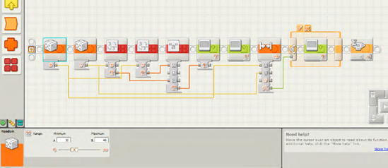
That's it. The RANGE block evaluates the statement and returns a True or False response. Let's build a small program for SPOT that can use the RANGE block. As usual, we'll start with the pseudo-code.
Me: SPOT, I want you to create a random number between 1 and 100, show it on the LCD screen, and tell me if it is inside the range of 40 to 60.
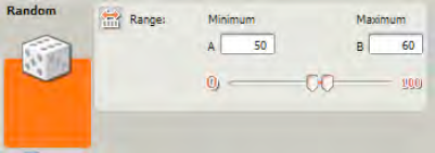
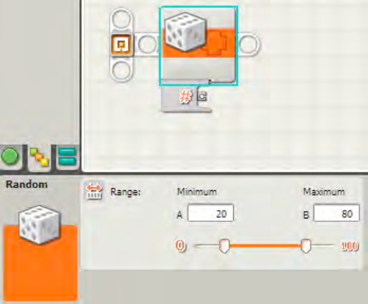
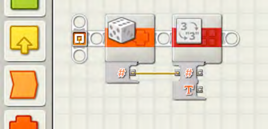
To do this, we place one RANDOM block onto the beam and configure it as shown in Figure 16-1.
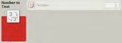
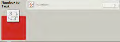
Next, I convert the number to text using a NUMBER TO TEXT block (see Figure 16-2). I have to do this because I want to display the random number on the LCD screen.
Next, I'll add a TEXT block to create a statement in the form of "A inside range 40 and 60," as shown in Figure 16-3.
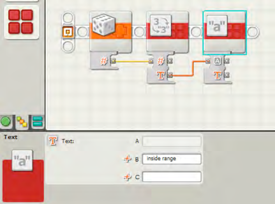
In Figure 16-3, the RANDOM block number is used as input to the NUMBER TO TEXT block. The TEXT block then takes this bit of text (A) and combines it with the statement "inside range."
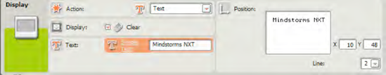
In Figure 16-4, I use a data wire to send the text from the TEXT block to a DISPLAY block configured to display text on Line 3 with position X=2 and Y=40 (see Figure 16-4).
![The DISPLAY block will display "[number] inside range."](http://imgdetail.ebookreading.net/hardware/2/9781430229766/9781430229766__lego-mindstorms-nxt-g__9781430229766__figs__1604.png)
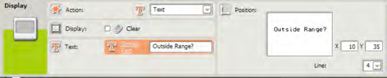
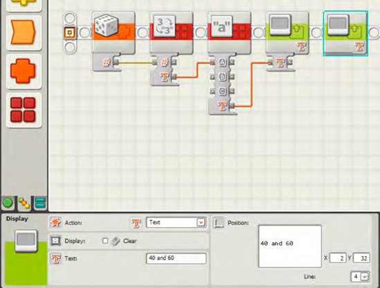
I need to add one more DISPLAY block, so I can add the text "40 and 60" on Line 4 with position X=2 and Y=32 (see Figure 16-5). Remember to remove the check from the Clear box, so the text in the first DISPLAY box doesn't disappear!
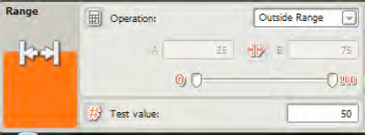
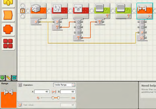
And now it's time to use the RANGE block to evaluate the statement. I drop the RANGE block onto the beam, as shown in Figure 16-6.
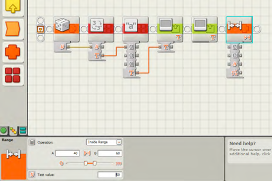
In Figure 16-6, you can see that I've selected Inside Range in the drop-down menu for the Operation section. I've also entered a value of 40 in the A field and 60 in the B field. I could have used the Slider bar to select the Lower Limit and Upper Limit for the range, but keep in mind that the Slider bar will only allow you to define a range between 0 and 100. If you need a larger range, you'll have to enter the values manually.
Also, I won't need to enter a value into the Test value field because I'm using a data wire to submit the random number to the RANGE block.
Note
The other option in the Operation drop-down menu is Outside Range. If I select this option, the statement will be True if the random number is outside the range of 40 to 60 and False if it is inside the range. Also notice that a Test Value can be entered in the Test value field. You can use this if you do not have a number from an outside block (a RANDOM block, for example) to use as input. And finally, the Upper Limit and Lower Limit can also be provided to the RANGE block dynamically by using data wires to provide input (in Number format) to the Upper Limit data plug and the Lower Limit data plug.
My next step is to run a data wire into the RANGE block that contains the original random number. There are two ways to do this. The first is to drag a data wire out of the NUMBER TO TEXT block (remember that this block has an output data plug for the original Number). I used that method in Chapter 15 for the COMPARE block. Now I want to show you the other method.
If you click the output Number data plug on the RANDOM block, you can drag a data wire to the input Test Value data plug on the RANGE block. I've done this in Figure 16-7. Notice that the original data wire going into the NUMBER TO TEXT block now splits into two wires—one still goes in the NUMBER TO TEXT block, and the other goes into the RANGE block.
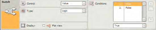
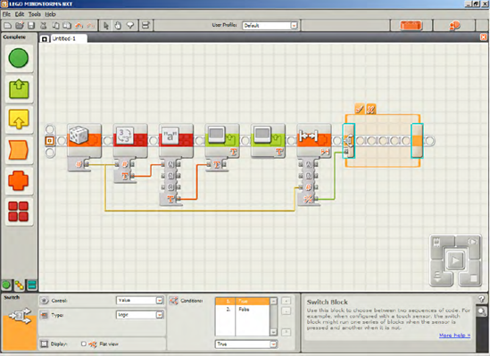
The pseudo-code tells SPOT to display on the LCD screen whether the statement "[number] inside range 40 and 60" is True or False. To do this, I've dropped a SWITCH block after the RANGE block. In the Display section, I uncheck the Flat view box; in the Control section, I choose Value; and in the Type section, I choose Logic. I also drag a data wire out of the output Result data plug on the RANGE block and connect it to the input data plug on the SWITCH block (see Figure 16-8).
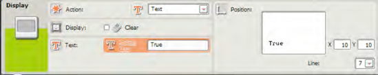
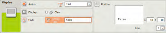
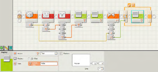
Now all that is left is for the LCD, screen to display "True" or "False." This is simple enough: I'll drop one DISPLAY block in the True tab (see Figure 16-9) that puts the word "True" on the LCD screen on Line 7. I'll drop another DISPLAY block in the False tab (see Figure 16-10) that puts the word "False" on the LCD screen on Line 7 (remember to remove the check from the Clear box so text on the LCD screen doesn't get erased). I'll position the True and False text so they are displayed on the LCD screen where X=12 and Y=8.
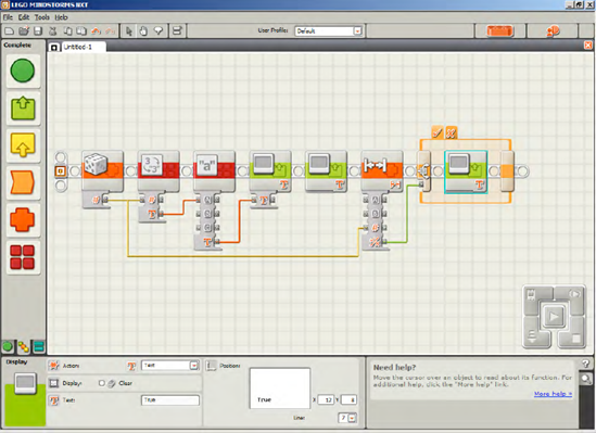
Now, if the statement is evaluated as True, the SWITCH block will execute the DISPLAY block found in the True tab. And if the statement is evaluated as False, the SWITCH block will execute the other DISPLAY block found in the False tab.
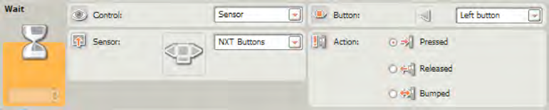
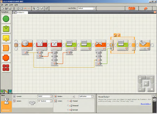
Next, I'll drop in a NXT BUTTON WAIT block and configure it to wait for the left button to be pressed (see Figure 16-11). This will allow me time to view the results.
And now I've got an exercise for you. It shouldn't be too difficult if you understand the program we've just created. One possible solution to the exercise is at the end of the chapter.
Modify the program to use two RANDOM blocks to create the Upper and Lower values used by the RANGE block. The Lower value should be between 30 and 40. The Upper value should be between 50 and 60. Use a third RANDOM block to generate the Test value between 5 and 95 and test whether this value falls outside the range. Use DISPLAY blocks to display the Upper and Lower values as well as the Test value and display True or False depending on whether the Test value falls outside the range.
When you're finished, continue on to Chapter 17, where I'll cover the LOGIC block. You should have a good understanding of Logic and how True and False statements are evaluated; the LOGIC block will add some more power to your robots by allowing you to control how items are evaluated before obtaining a True or False answer.
Figures 16-12 through 16-23 provide the full program and configuration panels for Exercise 16-1. Remember to uncheck the Clear boxes in the DISPLAY blocks so the text is not erased.