Appendix C. UML Basics
Unified Modeling Language (UML) is an object-modeling specification language that uses graphical notation to create an abstract model of a system. The Object Management Group governs UML. This modeling language can be applied to Java programs to help graphically depict such things as class relationships and sequence diagrams. The latest specifications for UML can be found at the OMG website. An informative book on UML is UML Distilled, Third Edition, by Martin Fowler (Addison-Wesley).
Class Diagrams
A class diagram represents the static structure of a system, displaying information about classes and the relationships between them. The individual class diagram is divided into three compartments: name, attributes (optional), and operations (optional). See Figure C-1 and the example that follows it.
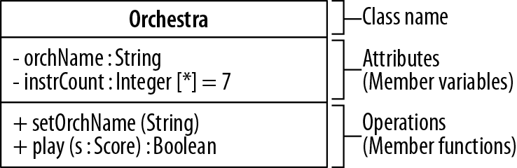
Figure C-1. Class diagram
// Corresponding code segmentclassOrchestra{// Class Name// AttributesprivateStringorchName;privateIntegerinstrCount=7;// OperationspublicvoidsetOrchName(Stringname){...}publicBooleanplay(Scores){...}}
Operations
The operations compartment is optional and includes member functions that represent the system’s behavior. The complete UML usage for operations is as follows:
visibilityname(parameter-list):return-type-expression{property-string}
Typically, only the operation names and parameter lists are represented.
Tip
{property-string} can be any of several properties such as {ordered} or {read-only}.
Visibility
Visibility indicators (prefix symbols) can be optionally defined for access modifiers. The indicators can be applied to the member variables and member functions of a class diagram (see Table C-1).
| Visibility indicators | Access modifiers |
|---|---|
~ |
package-private |
# |
|
- |
|
Object Diagrams
Object diagrams are differentiated from class diagrams by underlining the text in the object’s name compartment. The text can be represented in three different ways (see Table C-2).
|
Class name only |
|
Object name only |
|
Object and class name |
Object diagrams are not frequently used, but they can be helpful when detailing information, as shown in Figure C-2.
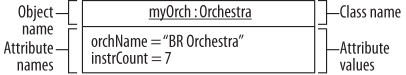
Figure C-2. Object diagram
Graphical Icon Representation
Graphical icons are the main building blocks in UML diagrams (see Figure C-3).
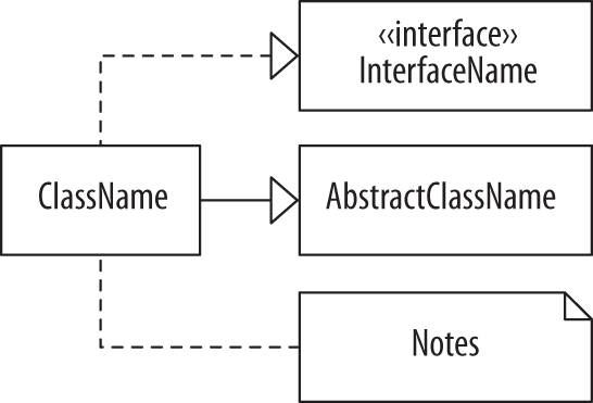
Figure C-3. Graphical icon representation
Classes, Abstract Classes, and Interfaces
Classes, abstract classes, and interfaces are all represented with their names in boldface within a rectangle. Abstract classes are also italicized. Interfaces are prefaced with the word interface enclosed in guillemet characters. Guillemets house stereotypes and in the interface case, a classifier.
Packages
A package is represented with an icon that resembles a file folder. The package name is inside the larger compartment unless the larger compartment is occupied by other graphical elements (i.e., class icons). In the latter case, the package name would be in the smaller compartment. An open arrowhead with a dashed line shows package dependencies.
The arrow always points in the direction of the package that is required to satisfy the dependency. Package diagrams are shown in Figure C-4.
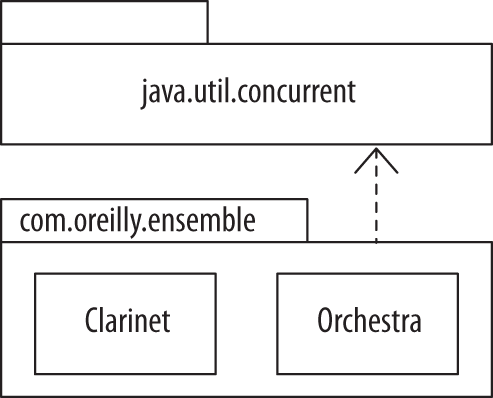
Figure C-4. Package diagrams
Connectors
Connectors are the graphical images that show associations between classes. Connectors are detailed in “Class Relationships”.
Multiplicity Indicators
Multiplicity indicators represent how many objects are participating in an association (see Table C-3). These indicators are typically included next to a connector and can also be used as part of a member variable in the attributes compartment.
| Indicator | Definition |
|---|---|
* |
Zero or more objects |
0..* |
Zero or more objects |
0..1 |
Optional (zero or one object) |
0..n |
Zero to n objects where n > 1 |
1 |
Exactly one object |
1..* |
One or more objects |
1..n |
One to n objects where n > 1 |
m..n |
Specified range of objects |
n |
Only n objects where n > 1 |
Role Names
Role names are utilized when the relationships between classes need to be further clarified. Role names are often seen with multiplicity indicators. Figure C-5 shows Orchestra where it performs one or more Scores.

Figure C-5. Role names
Class Relationships
Class relationships are represented by the use of connectors and class diagrams (see Figure C-6). Graphical icons, multiplicity indicators, and role names may also be used in depicting relationships.
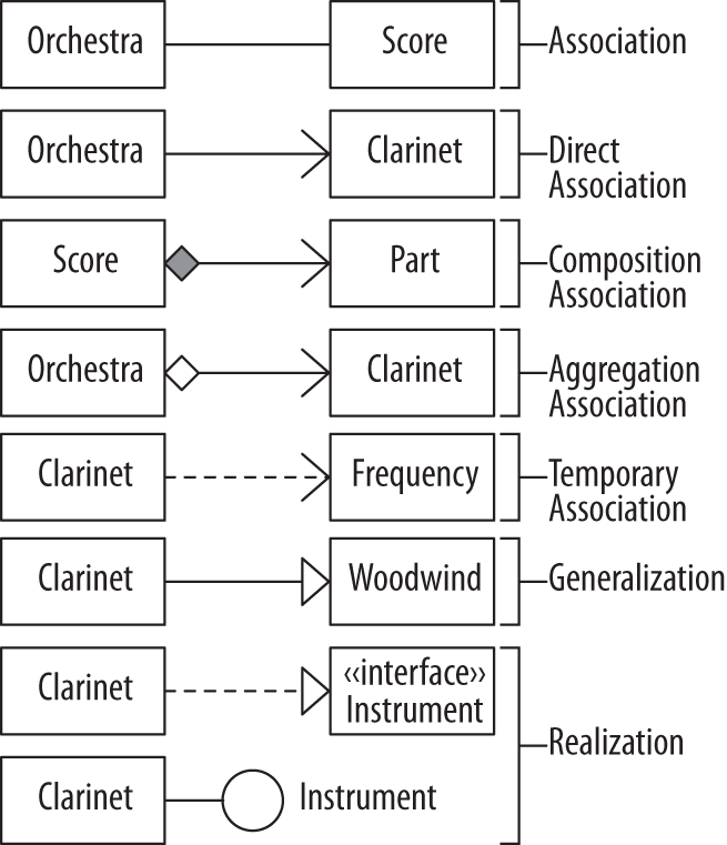
Direct Association
Direct association, also known as navigability, is a relationship directing the source class to the target class. This relationship can be read as “Orchestra has a Clarinet.” Class attributes and multiplicities can be included at the target end. Navigability can be bidirectional between classes.
Composition Association
Composition association, also known as containment, models a whole-part relationship, where the whole governs the lifetime of the parts. The parts cannot exist except as components of the whole. This is a stronger form of association than aggregation. This can be read as “Score is composed of” one or more parts.
Temporary Association
Temporary association, better known as dependency, is represented where one class requires the existence of another class. It’s also seen in cases where an object is used as a local variable, return value, or a member function argument. Passing a frequency to a tune method of class Clarinet can be read as class Clarinet depends on class Frequency, or “Clarinet uses a Frequency.”
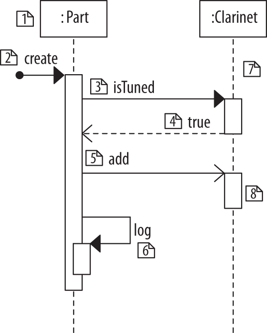
Sequence Diagrams
UML sequence diagrams are used to show dynamic interaction between objects (see Figure C-7). The collaboration starts at the top of the diagram and works its way toward the bottom.