

IBM VM Recovery Manager High Availability GUI deployment
This chapter introduces the IBM VM Recovery Manager High Availability (HA) GUI for Power Systems deployment.
The following topics are described in this chapter:
4.1 Installing the GUI filesets
To use the VM Recovery Manager HA by using the GUI, you must install the GUI server fileset on a system to manage KSYS nodes by using the GUI. The logical partition (LPAR) in which you want to install the GUI filesets must be running IBM AIX 7.2 with Technology Level 2 Service Pack 1 (7200-02-01) or later. You can choose to install the GUI server fileset on one of the KSYS nodes. You must install the following GUI server filesets before you start the GUI. The GUI agent filesets are automatically installed along with the KSYS filesets. To install the GUI server filesets, complete the following steps:
1. Install the GUI server fileset based on the following scenarios:
If you are installing the GUI server filesets on one of the KSYS nodes, run the following command:
installp -acFXYd fileset_location -V2 [-e filename.log] ksys.ui.server
If you are installing the GUI server filesets on a separate system that manages all the KSYS nodes, run the following command:
installp -acFXYd fileset_location -V2 [-e filename.log] ksys.ha.license ksys.ui.server ksys.ui.common
Example 4-1 shows how to install the GUI server filesets on the KSYS node.
Example 4-1 Installing the GUI server filesets on the KSYS node
# installp -acFXYd . ksys.ui.server
.
.
.
#######################################################################
#######################################################################
##
## The IBM VMRestart for AIX graphical user interface
## (GUI) server installation is starting. To complete the process,
## you must install additional files when the installation completes.
## These additional files were not included in the server fileset
## because they are licensed under the General Public License (GPL).
## However, you can automatically download the required files by
## running the following script:
##
## /opt/IBM/ksys/ui/server/dist/server/bin/vmruiinst.ksh
##
#######################################################################
#######################################################################
.
.
.
Installation Summary
--------------------
Name Level Part Event Result
-------------------------------------------------------------------------------
ksys.ui.server 1.3.0.1 USR APPLY SUCCESS
ksys.ui.server 1.3.0.1 ROOT APPLY SUCCESS
2. Install the open source software packages, which are not included in the installed filesets, based on the following scenarios.
If the GUI server LPAR is connected to the internet, run the command in the GUI server LPAR as shown in Example 4-2. The command downloads and installs the remaining files that are not included in the filesets because these files are licensed under the General Public License (GPL).
Example 4-2 Installing open source software packages on LPAR to connect to the internet
# /opt/IBM/ksys/ui/server/dist/server/bin/vmruiinst.ksh
Warning: "/tmp/vmruiinst.downloads" does not exist. Creating...
"/tmp/vmruiinst.downloads" has been created.
Checking if the requisites have already been downloaded...
** "info-4.13-3.aix5.3.ppc.rpm" needs to be retrieved.
** "cpio-2.11-2.aix6.1.ppc.rpm" needs to be retrieved.
** "readline-6.2-2.aix5.3.ppc.rpm" needs to be retrieved.
** "libiconv-1.13.1-2.aix5.3.ppc.rpm" needs to be retrieved.
** "bash-4.2-5.aix5.3.ppc.rpm" needs to be retrieved.
** "gettext-0.17-6.aix5.3.ppc.rpm" needs to be retrieved.
** "libgcc-4.9.2-1.aix6.1.ppc.rpm" needs to be retrieved.
** "libgcc-4.9.2-1.aix7.1.ppc.rpm" needs to be retrieved.
** "libstdc++-4.9.2-1.aix6.1.ppc.rpm" needs to be retrieved.
** "libstdc++-4.9.2-1.aix7.1.ppc.rpm" needs to be retrieved
Total number of requisite downloads needed: 10
.
.
.
To use the VM Restart for AIX graphical user interface (GUI), you
must install third-party files. These third-party files were not included in
the server filesets because they are licensed under the General Public License
(GPL). This script downloads and installs the files that are required by
SQLite and Node.js.
SQLite dependencies: | Node.js dependencies:
========================================= | =======================
bash info | libgcc
libiconv readline | libstdc++
gettext cpio |
The files that are required for Node.js are used on the server, and are also
installed on each cluster node automatically during the cluster discovery
operation.
IBM does not offer support for these files if the files are used outside the
context of the VM Restart GUI.
Do you want to download and install these files? (y/n)
Y
.
.
.
Attempting to start the server...
The server was successfully started.
The installation completed successfully. To use the VM Restart GUI,
open a web browser and enter the following URL:
https://9.x.x.x:3000/login
After you log in, you can add existing clusters in your environment to the
VM Restart GUI.
If the GUI server LPAR is configured to use an HTTP/HTTPS proxy to access the internet, run the following command in the GUI server LPAR to specify the proxy information:
/opt/IBM/ksys/ui/server/dist/server/bin/vmruiinst.ksh [-p <HTTP_PROXY>] [-P <HTTPS_PROXY>]
|
Tip: You can also specify the proxy information by using the http_proxy environment variable.
|
If the GUI server LPAR is not connected to the internet, complete the following steps:
a. Copy the vmruiinst.ksh file from the GUI server LPAR to a system that is running the AIX operating system and that has internet access.
b. Run the vmruiinst.ksh -d /directory command where /directory is the location where you want to download the remaining files. For example, /vmruiinst.ksh -d /tmp/vmrui_rpms.
c. Download the following prerequisite packages for the GUI server:
• info-4.13-3.aix5.3.ppc.rpm
• cpio-2.11-2.aix6.1.ppc.rpm
• readline-6.2-2.aix5.3.ppc.rpm
• libiconv-1.13.1-2.aix5.3.ppc.rpm
• bash-4.2-5.aix5.3.ppc.rpm
• gettext-0.17-6.aix5.3.ppc.rpm
• libgcc-4.9.2-1.aix6.1.ppc.rpm
• libgcc-4.9.2-1.aix7.1.ppc.rpm
• libstdc++-4.9.2-1.aix6.1.ppc.rpm
• libstdc++-4.9.2-1.aix7.1.ppc.rpm
d. Copy the downloaded files to a directory in the GUI server LPAR.
e. In the GUI server LPAR, run the vmruiinst.ksh -i /directory command where /directory is the location where you copied the downloaded files.
f. After the vmruiinst.ksh command completes, a message displays a URL for the VM Recovery Manager HA GUI server. Enter the specified URL in a web browser in the GUI server LPAR and start using the VM Recovery Manager HA GUI.
4.2 Configuring and discovering the VM Recovery Manager HA infrastructure by using the GUI only
This chapter demonstrates how to configure and discover the infrastructure of VM Recovery Manager HA from the start by using only the GUI.
Complete the following steps:
1. After installing the VM Recovery Manager HA GUI, use the URL that is presented at the end of the installation to log in to the GUI, as shown in the Figure 4-1.

Figure 4-1 VM Recovery Manager HA GUI login window
After logging in to the VM Recovery Manager HA GUI, the window that is shown in Figure 4-2 opens.

Figure 4-2 Welcome window for the VM Recovery Manager HA GUI
The AIX LPAR the VM Recovery Manager HA GUI installed can manage one KSYS to multiple KSYS subsystems.
– KSYS IP address
– Root user
– Password
– Cluster type

Figure 4-3 Adding KSYS Login information

Figure 4-4 Host Group Details window
4. In the HCM Selection window, enter the Hardware Management Console (HMC) information, as shown in Figure 4-5.

Figure 4-5 HMC Selection window
5. In the Host Selection window, there is a request to select the host that will be part of this host group. In this case, select host rt12, as shown in Figure 4-6.

Figure 4-6 Host Selection window: Adding host rt12
Figure 4-7 shows the selection of host rt11.

Figure 4-7 Host Selection window: Adding host rt11
6. In the Virtual I/O Server (VIOS) Selection window, select a VIOS from the hosts, as shown in Figure 4-8.

Figure 4-8 VIOS Selection window
7. In the Disk Section window, enter the disks to use as the Repository Disk and HA Pool Disk, as shown in Figure 4-9 on page 331.

Figure 4-9 Disk Selection window
8. In the VM Selection window, you are requested to select the virtual machine (VM) that will be managed on this host group. Select the VM and click Policies to change the VM-specific policies, as shown in Figure 4-10.

Figure 4-10 Changing the VM policies
Figure 4-11 shows the VM that is selected from host rt11.

Figure 4-11 Selecting a VM from host rt11
Figure 4-12 shows the VM that is selected from host rt12.

Figure 4-12 Selecting a VM from host rt12
The summary shows details of the host group that is configured, as shown in Figure 4-13 on page 333.

Figure 4-13 Summary Host Group configuration
9. Click Submit & Deploy. The deployment of the host group configuration starts, as shown in Figure 4-14.

Figure 4-14 Deploying the host group configuration
When the deployment finishes, the message that is shown in Figure 4-15 appears.

Figure 4-15 Finishing the deployment of the host group

Figure 4-16 VM Recovery Manager HA dashboard
4.3 VM Recovery Manager HA dashboard
This section shows the different features in the dashboard.
4.3.1 KSYS cluster features
To check and change the KSYS cluster policies, click ksyscluster, as shown in Figure 4-17.

Figure 4-17 The ksyscluster policies
To unregister the KSYS and set the Notifications Preferences, go to the Settings window and click Notification Preferences, as shown in Figure 4-18.

Figure 4-18 Setting the Notifications Preferences
To add or remove an HMC, click Edit, as shown in Figure 4-19.

Figure 4-19 Adding and removing an HMC
To check the ITSO_HG host group components and policies, click the ITSO_HG host group, as shown in Figure 4-20.

Figure 4-20 Host group policies
To add or remove a host from the host group, click Edit, as shown in Figure 4-21.

Figure 4-21 Adding or removing a host from the host group
To configure the collocation policies for the VMs, click Other Policies for VM, as shown in Figure 4-22.

Figure 4-22 Configuring collocation policies
Figure 4-23 shows the configuration of the Anti-Collocation policy for the VMs rt11005 and rt12005.

Figure 4-23 Configuring the Anti-Collocation policy
Clicking Discovery & Verify shows three discovery and verify options: Discovery Host Group, Verify Host Group, and Discovery and Verify Host Group, as shown in Figure 4-24.

Figure 4-24 Discover & Verify menu options
When you click Discovery and Verify Host Group, a confirmation window opens, as shown in Figure 4-25.

Figure 4-25 Confirming to run Discovery and Verify
Click Discovery and Verify and all running activities are displayed, as shown in Figure 4-26.
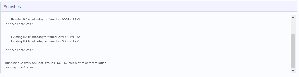
Figure 4-26 Running Discovery and Verify
To filter the event logs by Critical, Warning, Maintenance, and Informational event, click Events, as shown in Figure 4-27.

Figure 4-27 Filtering the Events log
To show detailed information, click the event log, as shown in Figure 4-28.

Figure 4-28 Information Event error detail
As shown in Figure 4-20 on page 336 (left side), you can also check the host group, HMC, and hosts, as shown in Figure 4-29.

Figure 4-29 Checking the host group components
When you select the host rt11, an information summary opens, as shown in Figure 4-30.

Figure 4-30 Host rt11 information summary
Click Policies, and the policies information from host rt11 appear, as shown in Figure 4-31 on page 340.

Figure 4-31 Policies information from host rt11
You can check on all VMs that are related to host rt11, as shown in Figure 4-32.

Figure 4-32 Checking the VMs that are related to host rt11
When you select the host rt12 (Figure 4-29 on page 339), an information summary window opens, as shown in Figure 4-33.

Figure 4-33 Host rt12 information summary
Click Policies, and the policies information from host rt12 appear, as shown in Figure 4-34.

Figure 4-34 Policies information about host rt12
You can check all VMs that are related to host rt12, as shown in Figure 4-35.

Figure 4-35 Checking VMs that are related to host rt12
When you select the VIOS rt11v1, an informational summary appears, as shown in Figure 4-36.

Figure 4-36 Checking the VIOS summary
When you click SSP Cluster for the rt11v1 VIOS, the cluster name and status appear, as shown in Figure 4-37.

Figure 4-37 Checking the SSP Cluster information from the VIO server

Figure 4-38 Checking the policy information for VIOS
Select the VM rt11001, as shown in Figure 4-32 on page 341. A summary opens, as shown in Figure 4-39.

Figure 4-39 Checking the VM summary
To check the application that is managed by the VM monitor (VMM) daemon, click Application, as shown in Figure 4-40.

Figure 4-40 Checking the application monitor

Figure 4-41 Checking the VM policies
4.4 Relevant move tests
This section shows the relevant VM Recovery Manager HA move tests.
4.4.1 VM Live Partition Mobility move test
This test performs a Live Partition Mobility (LPM) move of VM rt11001.
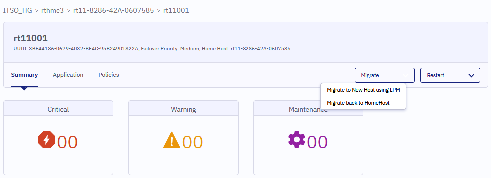
Figure 4-42 Migration to a new host by using LPM
The available hosts and the option for KSYS to decide the best host are shown. In this case, we select the host that is shown in Figure 4-43.

Figure 4-43 Selecting the host to migrate by LPM
The LPM activity message appears, as shown in Figure 4-44.

Figure 4-44 LPM activity
During the LPM activity, a purple signal appears, as shown in Figure 4-45.

Figure 4-45 Signal that is shown during LPM activity
After the LPM operation finishes, the dashboard shows VM rt11001 at host rt12, as shown in Figure 4-46.

Figure 4-46 Dashboard after LPM migration
Now, we test the option to migrate back to the home host, as shown in Figure 4-47.
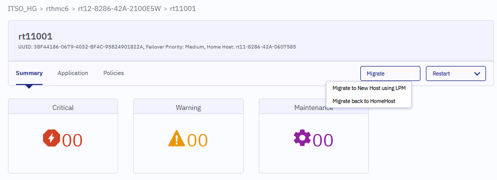
Figure 4-47 Migrating back to the home host
The same purple signal appears, as shown in Figure 4-48.

Figure 4-48 Signal that is shown while migrating back to the home host
After the LPM operation finishes, the dashboard shows VM rt11001 at host rt11, as shown in Figure 4-49.

Figure 4-49 Dashboard after the LPM migration
4.4.2 VM restart move test
This test performs a VM restart to move VM rt12001.
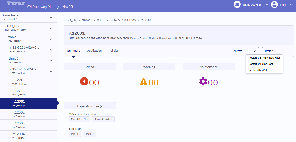
Figure 4-50 Migration to a new host by using restart
The available hosts appear, as shown in Figure 4-51.

Figure 4-51 Choosing the host to migrate due to a restart
During the restart activity, a red signal appears, as shown in Figure 4-52.

Figure 4-52 Signal shown during the VM restart activity
After the restart operation finishes, the dashboard shows VM rt12001 at host rt11, as shown in Figure 4-53.

Figure 4-53 Dashboard after the restart migration
Now, we test the option to Restart at Home Host, as shown in Figure 4-54.

Figure 4-54 Migrating back to the home host
The same red signal is shown in Figure 4-55.

Figure 4-55 Signal that is shown while migrating back to the home host
After the restart operation finishes, the dashboard shows VM rt12001 at host rt12, as shown in Figure 4-56.

Figure 4-56 Dashboard after the restart migration
4.4.3 Host LPM move test
In this test, the Host LPM moves all managed VMs from host rt12 to rt11.
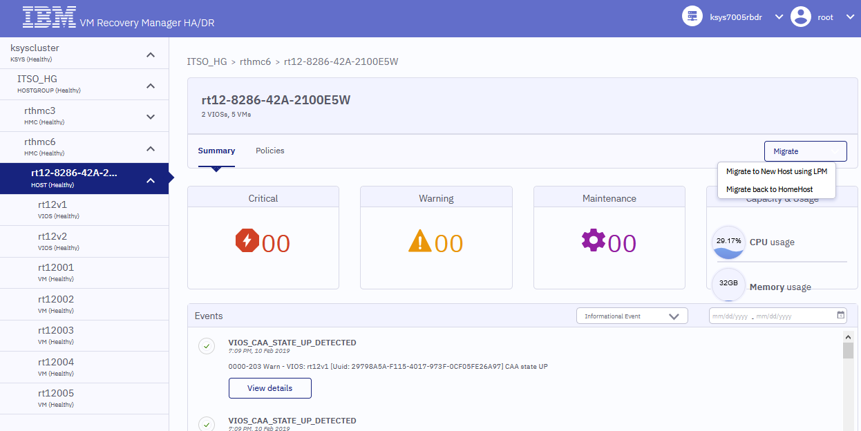
Figure 4-57 Migrating all VMs for one host by using LPM
The available hosts appear, as shown in Figure 4-58.

Figure 4-58 Choosing the host to migrate due to LPM
All VMs are now managed from host rt12 and a purple signal appears, as shown in Figure 4-59.

Figure 4-59 Signal shown during host LPM activity
After the LPM operation finishes, the dashboard shows that all VMs that are managed from host rt12 are migrated to host rt11, as shown in Figure 4-60.

Figure 4-60 Dashboard after the Host LPM migration
Now, we click Migrate Back to Home Host on all VMs from host rt12, as shown in Figure 4-61.

Figure 4-61 Migrating back all VMs for one host by using LPM

Figure 4-62 Restore messages for VMs
A purple signal appears, as shown in Figure 4-63.

Figure 4-63 Signal shown during host LPM activity
After the LPM operation finishes, the dashboard shows that all VMs that are managed from host rt12 are migrated back from host rt11, as shown in Figure 4-64.

Figure 4-64 Dashboard after the Host LPM migration
..................Content has been hidden....................
You can't read the all page of ebook, please click here login for view all page.