


Hardware overview
IBM z13 is the next step in the evolution of the mainframe family. It continues the evolution by introducing several innovations and expanding existing functions, building upon the z/Architecture.
The z13 is designed to deliver new levels of performance and capacity for large-scale consolidation and growth, and in support of cloud infrastructures, and also support for the next generation of digital signature security, cutting edge pattern recognition analytics for smart monitoring of system health, and enhanced environmental capabilities.
This chapter expands upon the overview of key hardware elements of the z13 provided in “Overview” on page 2, and compares it with previous IBM z Systems, where relevant.
This chapter describes the following topics:
2.1 The z13 highlights, models, and upgrades
The z13 models, and the improvements and upgrades over their predecessors, are described in this section.
2.1.1 IBM z13 highlights
Major enhancements of IBM z13 over its predecessors include the following features:
•Increased total system capacity: 168-way system (with 141 characterizable PUs) and more subcapacity settings, offering increased levels of performance and scalability to help enable new business growth.
•Six eight-core 5.0 GHz processor chips that can help improve the execution of processor-intensive workloads.
•Up to 10 TB of addressable real memory per system (with up to 10 TB real memory per logical partition) ensuring high availability in the memory subsystem by the proven technology of redundant array of independent memory (RAIM).
•A 96 GB fixed hardware system area (HSA) that is managed separately from client-purchased memory (three times the size of the IBM zEnterprise EC12).
•Fourth-generation high frequency, second-generation out-of-order design, with single-instruction, multiple-data (SIMD) processor, which increases parallelism to enable analytics processing, Simultaneous multithreading (SMT-2) increases processing efficiency and throughput, and the number of instructions in flight increases by 42.8%.
•Processor cache structure improvements and larger cache sizes that can benefit most production workloads: Compared to zEC12, first level of cache (L1 private) is increased from 64 KB to 96 KB for instructions and from 96 KB to 128 KB for data. The size of second level of cache (L2) doubles from 1 MB to 2 MB for data and instructions, increases third level of cache (L3) from 48 MB to 64 MB, and fourth level of cache (L4) from 384 MB to 480 MB along with the addition of 224 MB for non-Data Integrated Coherent (NIC) Directory for L3.
•Improved cryptographic functionality and performance: These are achieved by having one dedicated cryptographic coprocessor per core.
•Channel subsystem enhancement for I/O resilience: The z13 channel subsystem increases the number of logical channel subsystems (LCSSs) from four to six, augmenting the number of logical partitions from 60 to 85. A fourth subchannel set is implemented to improve addressability. The number of I/O devices supported by all FICON channel features is augmented from 24 K to 32 K devices.
IBM z13 also introduces several features and functions:
•LPAR resources allocation algorithms for PUs and memory.
•Generation of flash solid-state drives (SSD) for the Flash Express feature. These SSDs are mounted in Flash Express feature cards and can be used to handle paging workload spikes and improve availability.
•Crypto Express5S, with enhanced support of cryptographic functions and 85 domains.
•PCIe Gen3 I/O fanout adapters with 16 GBps bus.
•RoCE Express feature has new functionality: Second port is now available for use, and also the ability to share adapters between LPARs.
•Integrated Coupling Adapter (ICA-SR) for coupling links.
•The 1U Support Elements (SEs) replace the SE notebooks.
•Redundant System Control Hubs (SCHs) replace the Bulk Power Hubs (BPHs)
•Optional rack mountable 1U Hardware Management Console (HMC) for installation on a customer supplied rack.
•Air cooled systems: cooling radiators with N+2 redundant design.
•IBM z Advanced Workload Analysis Reporter (IBM zAware) software appliance, which provides a smart solution for detecting and diagnosing anomalies in z/OS systems is now also available for Linux on z Systems.
In all, these enhancements provide options for continued growth, continuity, and ability to upgrade.
For an in-depth description of IBM z13 functions and features, see IBM z13 Technical Guide, SG24-8251.
2.1.2 IBM z13 models
The z13 has an assigned machine type (MT) of 2964, which uniquely identifies the central processor complex (CPC). The z13 is offered in five models:
•z13 N30: One CPC drawer and a maximum of 30 customizable processor units (PUs)
•z13 N63: Two CPC drawers and a maximum of 63 customizable PUs
•z13 N96: Three CPC drawers and a maximum of 96 customizable PUs
•z13 NC9: Four CPC drawers and a maximum of 129 customizable PUs
•z13 NE1: Four CPC drawers and a maximum of 141 customizable PUs
The model determines the maximum number of processor units that are available for characterization. PUs are delivered in single-engine (core) increments. The first four models use 39 PU cores on six PU SCMs in one CPC drawer, the fifth model, NE1, uses 42 PU on six SCMs, in each of the four CPC drawers to provide up to141 configurable PUs.
Spare PUs, system assist processors (SAPs), and one integrated firmware processor (IFP) are integral to the system. Table 2-1 provides a model summary that includes SAPs and spare PUs for the various models. For an explanation of PU characterization, see “Processor unit characterization” on page 36.
Table 2-1 z13 Model summary
|
Model
|
Drawers/PUs
|
CPs
|
Standard SAPs
|
Spares
|
Integrated firmware processor
|
|
N30
|
1/39
|
0–30
|
6
|
2
|
1
|
|
N63
|
2/78
|
0–63
|
12
|
2
|
1
|
|
N96
|
3/117
|
0–96
|
18
|
2
|
1
|
|
NC9
|
4/156
|
0–129
|
24
|
2
|
1
|
|
NE1
|
4/168
|
0–141
|
24
|
2
|
1
|
The z13 offers 231 capacity levels. There are 141 capacity levels that are given by the number of physically used central processors (CP), plus the possibility of 90 subcapacity models for the first 30 CPs. There is also one model for all Integrated Facility for Linux (IFL) or all Internal Coupling Facility (ICF) configurations. This topic is described in more detail in “Processor unit characterization” on page 36.
2.1.3 IBM z13 upgrades
Figure 2-1 summarizes the upgrade paths to the z13.

Figure 2-1 z13 upgrade paths
Concurrent upgrades of CPs, IFLs, ICFs, zAAPs, zIIPs, or SAPs are available for the z13. However, concurrent PU upgrades require that more PUs were physically installed (at a previous time), but not activated.
If an upgrade request cannot be accomplished within the specified configuration, a hardware upgrade is required. The upgrade enables the addition of one or more CPC drawers to accommodate the desired capacity. Additional CPC drawers can be installed concurrently. Upgrades from any z13 (model N30, N63, N96, HC9) to a model NE1, are disruptive because this upgrade requires the replacement of all installed CPC drawers.
Spare PUs are used to replace defective PUs. There are always two spare PUs on a z13. In the rare event of a PU failure, a spare PU is concurrently and transparently activated, and assigned the characteristics of the failing PU.
When a z196 with a zBX Model 002 is upgraded to z13, the zBX is converted to a Model 004. When a zEC12 with a zBX Model 003 is upgraded to z13, the zBX is converted to a Model 004. The virtualization and configuration data is preserved, however the upgrade process requires downtime.
2.2 Frames
The frames of the z13 are described in this section.
2.2.1 IBM z13 frames
The z13 is always a two-frame system: the A Frame and the Z Frame. The z13 can be delivered as an air-cooled system or as a water-cooled system.
Figure 2-2 shows an internal front view of the two frames for an air-cooled system. The two frames form the central processing complex (CPC). The number and type of drawer that holds I/O features can vary and depends on the number of I/O features. For a new build system, a combination of up to five PCIe I/O drawers can be installed. A miscellaneous equipment specification (MES) can carry forward up to two I/O drawers (8 slot I/O drawer). This configuration provides for a maximum number of 16 non-PCIe feature cards that can be carried forward.
Figure 2-2 shows the air-cooled system with the maximum of five PCIe I/O drawers.
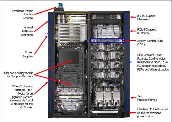
Figure 2-2 z13 internal front view: air-cooled CPC
Figure 2-3 shows an internal front view of the two frames of a water-cooled CPC without the top exit I/O cable and top exit power cable option.

Figure 2-3 z13 internal front view: water-cooled CPC
Top exit I/O and power cabling
z13 and its predecessor, the zEC12, have the option of ordering the infrastructure to support the top exit of fiber optic cables (FICON, OSA, 12x InfiniBand, 1x InfiniBand, ICA SR and RoCE) and copper cables for the 1000BASE-T Ethernet features.
On the z13, the top exit capability is designed to provide an additional option, the overhead power cabling option. Figure 2-2 on page 29 shows this overhead power cable feature, present on the Z Frame. Instead of all the cables exiting under the CPC to under the raised floor, there is now the flexibility to choose the options that best meet the data center requirements. A non-raised floor installation of the z13 air-cooled systems is also possible. Top exit cabling can also help to increase air flow. These options are offered on new build and MES orders.
2.3 z13 CPC drawers, and single chip modules
The z13 system is a multiple CPC drawer system. Up to four CPC drawers can be installed in Frame A of a CPC. A CPC drawer slides into one of the four slots of the A Frame of the CPC. Figure 2-4 on page 32 shows the top view, no-cover CPC drawer. The location and structure of the CPC drawers are the same for both air-cooled and water-cooled systems.
Each CPC drawer contains the following elements:
•Eight single chip modules (SCM)
There are six PU SCMs and two storage controller (SC) SCMs. Each PU SCM includes eight PU cores.
SCMs are described in “IBM z13 single chip modules” on page 33. See Table 2-1 on page 27 for the model summary and the relation between the number of CPC drawers and number of available PUs.
•Memory
A minimum of 256 GB and a maximum of 2.5 TB memory are available for client use. See Table 2-2 on page 37 for details.
For 25 available slots, 20 or 25 memory DIMMs are plugged into these slots, providing up to 2.5 TB of customer-available memory installed in a CPC drawer.
•Fanouts
A combination of up to four InfiniBand host channel adapter (HCA3-Optical, HCA2-Copper) fanouts and up to 10 PCIe third generation (PCIe Gen3) fanouts.
Each fanout has one, two, or four ports, so up to 40 connections are supported:
– One-port PCIe 16 GBps I/O fanout, each supporting one domain in 32-slot PCIe I/O drawers)
– ICA SR two-port fanout, for coupling links (two links, 8 GBps each),
– HCA3-O 12x InfiniBand fanout, for coupling links (two ports at 6 GBps each)
– HCA3-O LR 1x InfiniBand fanout, for coupling links (four ports, 5 Gbps each).
– HCA2-Copper fanouts (two ports per fanout): supported only for I/O drawers that are carried forward, for a maximum of two features.
•Two Distributed Converter Assemblies (DCA) that provide power to the CPC drawer
Loss of one of the DCAs leaves enough power to satisfy the power requirements of the entire drawer. The DCAs can be concurrently maintained.
Figure 2-4 on page 32 shows a view of a z13 CPC drawer (without the containing box).

Figure 2-4 z13 CPC drawer structure and components
The z13 continues the evolution in system scalability, providing opportunity for server consolidation in a multiple CPC drawer system structure. As shown in Figure 2-5 and Figure 2-6 on page 33, all CPC drawers are interconnected with high-speed communications links through the L4 shared caches. The z13 has 960 MB of L4 cache per CPC drawer, which is 2.5 times larger than its predecessor.
This design used for PU and SC interconnect allows the system to be operated and controlled by the PR/SM facility as a symmetrical, memory-coherent multiprocessor system (SMP).
Figure 2-5 shows the z13 inter-CPC drawer communication structure.

Figure 2-5 z13 CPC drawer communication topology
The point-to-point connection topology shown Figure 2-6 allows direct communication between all CPC drawers.

Figure 2-6 z13 CPC drawer interconnect topology (four drawers)
Although the z13 potentially includes several hundred processor chips, only the z/Architecture processor chips are described next.
IBM z13 single chip modules
The single chip modules (SCM), shown in Figure 2-7, are high-performance, glass-ceramic chips, providing the highest level of processing integration in the industry. The SCMs are the heart of the system. The figure shows the size compared to the currency of one US dime.

Figure 2-7 z13 PU and SC chip SCMs
Each z13 processor unit (PU) chip has eight cores. All chips use complementary metal-oxide of silicon (CMOS1) 14S0 technology. CMOS 14S0 is a state-of-the-art microprocessor technology that is based on 17-layer copper interconnections and Silicon-On-Insulator (SOI) technologies. The chip lithography line width is 0.022 µm (22 nm). The processor unit chip contains close to 3,990,000,000 transistors in a 678.8 mm2 die.
There are eight single chip modules (SCMs) per CPC drawer. Six of these SCMs hold the processor chips (PU chips) and two SCMs hold storage control (SC) chips. Each PU chip has six, seven, or eight active cores, L1, L2, and L3 caches; the two SC chips holds L4 caches, as shown in Figure 2-8.
Two CPC drawer configurations are offered with 39 or 42 PUs. All the models employ CPC drawers with 39 PUs except for the model NE1, which has four CPC drawers with 42 active PUs, for a total of 168 PUs.
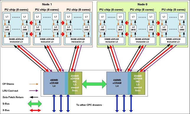
Figure 2-8 z13 CPC drawer chips and cache structure
Each SC chip packs 480 MB of eDRAM cache, interface logic for three PU chips each, and SMP fabric logic, into 678.78 mm2. The two SC chips are configured to provide a single 960 MB L4 cache that is shared by all cores in the CPC drawer. This amount of cache gives a total of 3.8 GB of cache if all four CPC drawers are implemented, yielding outstanding SMP scalability on real-world workloads.
2.4 Processor chip
The z13 features a high-frequency, eight-core processor chip (PU chip), with an advanced microprocessor design, a robust cache hierarchy, that incorporates SMT2 and SIMD3 architectures along with an SMP4 design that is optimized for enterprise database and transaction processing workloads, and for workloads such as Java and Linux.
The PU chip uses leading-edge technology and circuit design techniques while building on the rich heritage of mainframe system design, including industry-leading reliability, availability, and serviceability. Functions and features that are introduced with the z13 enable increased software efficiency and scalability, while maintaining full compatibility with existing software. Further details are given in 3.2.1, “Microprocessor” on page 68.
2.5 Processor unit
The processor unit (PU) is the generic term for a z/Architecture processor. A PU is embedded in a z Systems chip core. Each PU is a superscalar processor with the following attributes:
•Up to six instructions can be decoded per clock cycle.
•Up to ten instructions can be in execution per clock cycle.
•Instructions can be issued out-of-order. A high-frequency, low-latency pipeline, providing robust performance across a wide range of workloads, is used.
•Memory accesses might not be in the same instruction order (out-of-order operand fetching).
•Most instructions flow through a pipeline with varying numbers of steps for various types of instructions. Several instructions can be in progress at any moment, subject to the maximum number of decodes and completions per cycle.
PU chip cache
The on-chip cache for the PU chip is as follows:
•Each PU (core) has an L1 cache (private) that is divided into a 96 KB cache for instructions and a 128 KB cache for data.
•Each PU (core) also has a private L2 cache, with 2 MB D-cache (D is data) and 2 MB I-cache (I is instruction).
•In addition, each PU chip contains an 64 MB L3 cache, which is shared by all eight PUs (cores) on the chip. The shared L3 cache uses eDRAM.
The cache structure of z13 is shown in Figure 2-8 on page 34. This implementation optimizes performance of the system for high-frequency processors.
Each L1 cache has an associated translation lookaside buffer (TLB) of 512 entries. In addition, a secondary TLB is used to further enhance performance. This structure supports large working sets, multiple address spaces, and a two-level virtualization architecture.
CPU sparing
Hardware fault detection is embedded throughout the design and combined with comprehensive instruction-level retry and dynamic CPU sparing. This provides the reliability and availability that is required for true mainframe quality.
On-chip cryptographic hardware
Dedicated on-chip cryptographic hardware includes extended key and hash sizes for the Advanced Encryption Standard (AES) and Secure Hash Algorithm (SHA) algorithms, and UTF8 to UTF16 conversion support. It is available to any processor type (CP, zIIP, IFL).
Software support
The z13 processor provides full compatibility with existing software for ESA/390 and z/Architecture, while extending the Instruction Set Architecture (ISA) to enable enhanced function and performance. Several hardware instructions that support more efficient code generation and execution are introduced. Examples are as follows:
•Hardware decimal floating point (HDFP)
•Transactional Execution (TX) facility
•Runtime Instrumentation facility
•Single-instruction, multiple-data (SIMD)
These features are further described in Chapter 3, “Key functions and capabilities of IBM z13” on page 59.
Processor unit characterization
Processor units are ordered in single increments. The internal system functions, which are based on the configuration that is ordered, characterize each processor unit (core) into one of various types during initialization of the system, which is often called a power-on reset (POR) operation. Characterizing PUs dynamically without a POR is possible using a process called Dynamic PU Reassignment. A processor unit that is not characterized cannot be used.
Each PU (core) can be characterized as follows:
•Central processor (CP)
•Integrated Facility for Linux (IFL) processor
•z Integrated Information Processor (zIIP)
•Internal Coupling Facility (ICF)
•System assist processor (SAP)
•Integrated firmware processor (IFP)
At least one CP must be purchased with a zIIP or before a zIIP can be purchased. Clients can purchase up to two zIIPs for each purchased CP (assigned or unassigned) on the system. However, a logical partition definition can go behind the 1:2 ratio. For example, on a system with two CPs, a maximum of four zIIPs can be installed. A logical partition definition for that system can contain up to two logical CPs and four logical zIIPs. Another possible configuration is one logical CP and three logical zIIPs.
Converting a PU from one type to any other type is possible again, by using the Dynamic PU Reassignment process. These conversions happen concurrently with the operation of the system.
|
zIIP processors: The addition of ICFs, IFLs, zIIPs, and system assist processors (SAP) to a CPC does not change the system capacity setting or its MSU rating (only CPs do). IBM does not impose any software charges on work that is dispatched on zIIP processors.
zAAP processors: The zEC12 and zBC12 were the last z Systems servers to offer support for zAAP specialty engine processors. IBM supports running zAAP workloads on zIIP processors (“zAAP on zIIP”). This change is intended to help simplify capacity planning and performance management, while still supporting all the currently eligible workloads. IBM has provided a PTF for APAR OA38829 on z/OS V1R12 and V1R13. This PTF removes the restriction that prevents workloads eligible for zAAP from running on zIIP processors when a zAAP is installed on the server.
|
2.6 Memory
This section discusses memory subsystem for the z13.
2.6.1 IBM z13 memory
Maximum physical memory size is directly related to the number of CPC drawers in the system. Because part of the physically installed memory is used to implement the RAIM design, a z13 system has more memory installed than ordered. This configuration results in up to 2.5 TB of available memory per CPC drawer and up to 10 TB for a four-drawer system.
The HSA memory has a fixed amount of 96 GB and is managed separately from client memory. Therefore, theoretically, up to 2.5 TB on the one CPC drawer model and up to 10 TB on the four CPC drawer models can be ordered. Because of some dependencies on the memory granularity, the maximum number of orderable memory can vary from the theoretical number.
Table 2-2 lists the maximum and minimum memory sizes for each z13 model.
Table 2-2 z13 models memory sizes
|
Model
|
Number of CPC drawers
|
Client memory (GB)
|
|
N30
|
1
|
256 GB to 2560 GB
|
|
N63
|
2
|
512 GB to 5120 GB
|
|
N96
|
3
|
768 GB to 7669 GB
|
|
NC9
|
4
|
1024 GB to 10 TB
|
|
NE1
|
4
|
1024 GB to 10 TB
|
On z13 systems, the granularity for memory orders varies from 32 GB to 512 GB. Table 2-3 shows the memory granularity depending on installed client memory.
Table 2-3 z13 memory granularity
|
Memory increment (GB)
|
Client (offered) memory (GB)
|
|
32
|
64 to 192
|
|
64
|
256 to 448
|
|
96
|
544 to 928
|
|
128
|
1056 to 1440
|
|
256
|
1696 to 6048
|
|
512
|
6560 to 10144
|
Physically, memory is organized in the following ways:
•A CPC drawer always contains a minimum of 320 GB physically installed memory where 256 GB are usable memory.
•A CPC drawer can have more installed memory than enabled. The excess amount of memory can be enabled by a Licensed Internal Code load.
•Memory upgrades are satisfied from already installed unused memory capacity until exhausted. When no more unused memory is available from the installed memory cards, either the cards must be upgraded to a higher capacity or the addition of a CPC drawer with more memory is necessary.
When activated, PR/SM tries to allocate a logical partition’s memory in a single CPC drawer and, if not possible, it can use memory resources located in any CPC drawer. No matter which CPC drawer the memory is in, a logical partition has access to that memory if allocated. Despite the CPC drawer structure, the z13 is still a symmetric multiprocessor (SMP) system.
A memory upgrade is concurrent when it requires no change of the physical memory cards. A memory card change is disruptive when no use is made of Enhanced Drawer Availability (EDA). For a description of EDA, see IBM z13 Technical Guide, SG24-8251.
For a model upgrade that results in the addition of a CPC drawer, the minimum memory increment is added to the system. Remember that the minimum usable memory size in a CPC drawer is 256 GB. During a model upgrade, the addition of a CPC drawer is a concurrent operation. The addition of the physical memory that is in the added drawer is also concurrent.
2.6.2 Concurrent memory upgrade
Memory can be upgraded concurrently by using Licensed Internal Code Configuration Control (LICCC) if physical memory is available, as described in the previous section. The plan ahead memory function that is available with the z13 enables nondisruptive memory upgrades by having in the system pre-plugged memory, which is based on a target configuration. Pre-plugged memory is enabled through an LICCC order that is placed by the client.
2.6.3 Redundant array of independent memory (RAIM)
The z196 introduced the redundant array of independent memory (RAIM) to z Systems, making the memory subsystem essentially a fully fault-tolerant N+1 design. The RAIM design automatically detects and recovers from failures of dynamic random access memory (DRAM), sockets, memory channels, or dual inline memory module (DIMM).
The RAIM design is fully integrated in the z13 and is enhanced to include one Memory Controller Unit (MCU) per processor chip with five memory channels and one DIMM per channel. A fifth channel in each MCU enables memory to be implemented as a RAIM. This technology has significant RAS capabilities in error correction. Bit, lane, DRAM, DIMM, socket, and complete memory channel failures, including many types of multiple failures, can be detected and corrected.
Patented error correction technology in the memory subsystem provides the most robust error correction from IBM to date. Two full DRAM failures per rank can be spared and a third full DRAM failure corrected. DIMM level failures, including components such as the memory controller application-specific integrated circuit (ASIC), the power regulators, the clocks, and the system board can be corrected.
Memory channel failures, such as signal lines, control lines, and drivers/receivers on the SCM, can be corrected. Upstream and downstream data signals can be spared by using two spare wires on both the upstream and downstream paths. One of these signals can be used to spare a clock signal line (one upstream and one downstream).
2.6.4 Hardware system area (HSA)
The hardware system area (HSA) is a fixed-size reserved area of memory, separate from the client-purchased memory. The HSA is used for several internal functions, but the bulk is used by channel subsystem functions. The HSA has grown with each successive mainframe generation. On older systems, model upgrades and also new logical partition definitions or changes required preplanning and were sometimes disruptive.
The fixed size 96 GB HSA of the z13 is large enough to accommodate any logical partition (LPAR) definitions or changes, thus eliminating outage situations. In addition, planning needs are eliminated.
A fixed large HSA allows the dynamic I/O capability to be enabled by default. It also enables the dynamic addition and removal, without planning, of the following features:
•Logical partition to new or existing channel subsystem (CSS)
•CSS (up to six can be defined on z13)
•Subchannel set (up to four can be defined on z13)
•Devices, up to the maximum that is permitted, in each subchannel set
•Logical processors by type
•Cryptographic adapters
2.7 I/O system structure
The z13 supports two types of internal I/O infrastructure:s
•New generation 3 PCIe-based infrastructure for PCIe I/O drawers (PCIe Gen 3)
•InfiniBand-based infrastructure and I/O drawers (carry forward on an MES only)
The PCIe I/O infrastructure consists of the following features:
•New PCIe Gen3 fanouts in the z13 CPC drawer which support 16 GBps connectivity to the PCIe I/O drawer (zEC12 used PCIe Gen2 fanouts at 8 GBps)
•Up to five 7U PCIe I/O drawers each with 32 slots (eight slots per I/O domain) for PCIe I/O features
The InfiniBand I/O infrastructure (carry forward only) consists of the following features:
•InfiniBand fanouts in the z13 CPC drawer, which support the 6 GBps InfiniBand I/O interconnect
•InfiniBand I/O card domain multiplexers with redundant I/O interconnect in the following configuration: up to two, 5U, 8-slot, 2-domain I/O drawer (carry forward only)
•Selected non-PCIe I/O features (carry forward only)
|
Ordering of I/O features: Ordering of I/O feature types determines the appropriate mix of PCIe I/O drawers and I/O drawers (order-dependent).
|
Figure 2-9 shows a high-level view of the I/O system structure for the z13.

Figure 2-9 z13 I/O system structure
The z13 supports five fanout types (for fanout location, see also Figure 2-10 on page 41), which are located at the front on the z13 CPC drawer:
•ICA SR
•HCA3-O
•HCA3-O LR
•PCIe Gen3
•HCA2-C (carry forward only)
The HCA3-O LR fanout includes four ports, the PCIe Gen3 fanout with one port, and all other fanouts have two ports.
The following types of internal I/O connectivity support the PCIe I/O drawer and I/O drawer:
•PCIe connections to the PCIe I/O drawers from the PCIe fanouts through copper cables. The I/O features supported through the one port on the fanouts are listed in 2.8, “I/O features” on page 42.
•InfiniBand (IFB) connections to the legacy I/O drawers from the host channel adapter (HCA2-C) fanouts through copper cables in only a carry-forward MES5. The two ports in the fanout are dedicated to connect to an InfiniBand multiplexer (IFB-MP) card in the I/O drawer.
For coupling link connectivity (Parallel Sysplex or STP configuration), the z13 supports the following fanouts:
•ICA SR
•HCA3-O
•HCA3-O LR
The z13 CPC drawer (Figure 2-10) can have up to ten 1-port PCIe Gen3 fanouts (numbered LG02 to LG06 and LG11 to LG15) and up to four 2-port or 4-port InfiniBand fanouts for each CPC drawer, (numbered LG07 to LG10), which are used to connect to I/O drawers, PCIe I/O drawers, or for Parallel Sysplex InfiniBand and PCIe connectivity. In a system that is configured for maximum availability, alternate paths maintain access to critical I/O devices, such as disks and networks.
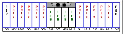
Figure 2-10 z13 CPC drawer front view
The PCIe I/O drawer is a two-sided drawer (I/O features on both sides) that is 7U high. The drawer contains 32 slots, four switch cards (two in the front and two in the rear) to support four I/O domains, each containing eight features of any type (FICON Express16S, FICON Express8S, OSA-Express5S, OSA-Express4S, Crypto Express5S, Flash Express, zEDC Express, and 10GbE RoCE Express). Two DCAs to provide the redundant power, and two air moving devices (AMD) provide redundant cooling to the PCIe I/O Drawer.
Each (legacy) I/O drawer supports two I/O domains (A and B) for a total of eight I/O slots. Each I/O domain uses an IFB-MP card in the I/O drawer and a copper cable to connect to a host channel adapter (HCA) fanout in the CPC drawer.
All features in the I/O drawer are installed horizontally. The two DCAs distribute power to the I/O drawer.
The IFB-MP cards are installed at location 09 at the rear side of the I/O drawer. The I/O features are installed from the front and rear sides of the I/O drawer. Two I/O domains are supported. Each I/O domain has up to four FICON Express8 features. The FICON Express8 I/O features are connected to the IFB-MP card through the backplane board.
2.8 I/O features
The z13 supports two internal I/O infrastructure types:
•A PCIe-based infrastructure for PCIe I/O drawers, which supports the following I/O features:
– FICON Express16S
– FICON Express8S
– OSA-Express5S
– OSA-Express4S
– 10GbE RoCE Express
– Crypto Express5S
– Flash Express
– zEDC Express
•An InfiniBand-based infrastructure for I/O drawers, which supports the following I/O feature:
– FICON Express8
All migration offerings and exchange programs offer FICON Express8S, OSA-Express5S, OSA-Express4S, Flash Express, zEDC Express, and 10GbE RoCE Express features as carry forward only. The following features are no longer orderable for z13:
•ESCON
•FICON Express4
•OSA-Express3
•ISC-3
•Crypto Express4S
•Crypto Express3
See Table B-1 on page 166 for more details.
|
Features available only when carried forward: FICON Express8 and OSA-Express4S features are available only when carried forward on upgrades.
|
2.8.1 FICON Express16S
Two types of transceivers for FICON Express16S are supported on a new build z13, one long wavelength (LX) laser version, and one short wavelength (SX) laser version:
•FICON Express16S LX feature
•FICON Express16S SX feature
Each port supports attachment to the following elements:
•FICON/FCP switches and directors that support 4 Gbps, 8 Gbps, or 16 Gbps
•Control units (storage subsystems) that support 4 Gbps, 8 Gbps, or 16 Gbps
FICON Express16S LX feature
The FICON Express16S LX feature occupies one I/O slot in the PCIe I/O drawer. It has two ports, each supporting an LC duplex connector and auto-negotiated link speeds of 4 Gbps, 8 Gbps, and 16 Gbps up to an unrepeated maximum distance of 10 km.
FICON Express16S SX feature
The FICON Express16S SX feature occupies one I/O slot in the PCIe I/O drawer. It has two ports, each supporting an LC duplex connector and auto-negotiated link speeds of 4 Gbps, 8 Gbps, and 16 Gbps up to an unrepeated maximum distance6 of up to 380 meters at 4 Gbps, 150 meters at 8 Gbps, or 100 meters at 16 Gbps.
2.8.2 FICON Express8S
|
Statement of Direction1: The IBM z13 server will be the last z Systems server to offer ordering of FICON Express8S channel features. Enterprises that have 2 Gb device connectivity requirements must carry forward these channels.
|
1 All statements regarding IBM plans, directions, and intent are subject to change or withdrawal without notice. Any reliance on these statements of general direction is at the relying party’s sole risk and will not create liability or obligation for IBM.
Two types of transceivers for FICON Express8S are supported on a new build7 z13, one long wavelength (LX) laser version, and one short wavelength (SX) laser version:
•FICON Express8S 10KM LX feature
•FICON Express8S SX feature
Each port supports attachment to the following elements:
•FICON/FCP switches and directors that support 2 Gbps, 4 Gbps, or 8 Gbps
•Control units that support 2 Gbps, 4 Gbps, or 8 Gbps
FICON Express8S 10KM LX feature
The FICON Express8 10KM LX feature occupies one I/O slot in the I/O drawer. It has four ports, each supporting an LC duplex connector, and auto-negotiated link speeds of 2 Gbps, 4 Gbps, and 8 Gbps up to an unrepeated maximum distance of 10 km.
FICON Express8S SX feature
The FICON Express8S SX feature occupies one I/O slot in the I/O drawer. This feature has four ports, each supporting an LC duplex connector, and auto-negotiated link speeds of 2 Gbps, 4 Gbps, and 8 Gbps up to an unrepeated maximum distance8 of up to 500 meters at 2 Gbps, 380 meters at 4 Gbps, or 150 meters at 8 Gbps.
2.8.3 FICON Express8 (carry forward only)
|
The IBM z13 will be the last z Systems server to support FICON Express8 channels: IBM z13 will be the last high-end server to support FICON Express8. Enterprises should begin migrating from FICON Express8 channel features (#3325, #3326) to FICON Express16S channel features (#0418, #0419). FICON Express8 will not be supported on future high-end z Systems servers as carry forward on an upgrade.
|
The FICON Express8 features are available only when carried forward on upgrades. Two types of transceivers for FICON Express8 are supported on z13:
•FICON Express8 10KM LX feature
•FICON Express8 SX feature
FICON Express8 10KM LX feature
The FICON Express8 10KM LX feature occupies one I/O slot in the I/O drawer. It has four ports, each supporting an LC duplex connector, and auto-negotiated link speeds of 2 Gbps, 4 Gbps, and 8 Gbps up to an unrepeated maximum distance of 10 km.
FICON Express8 SX feature
The FICON Express8 SX feature occupies one I/O slot in the I/O drawer. This feature has four ports, each supporting an LC duplex connector, and auto-negotiated link speeds of 2 Gbps, 4 Gbps, and 8 Gbps up to an unrepeated maximum distance8 of up to 500 meters at 2 Gbps, 380 meters at 4 Gbps, or 150 meters at 8 Gbps.
2.8.4 OSA-Express5S
This section describes the connectivity options that are offered by the OSA-Express5S features. The following OSA-Express5S features can be installed on z13:
•OSA-Express5S 10 Gigabit Ethernet (GbE) Long Reach (LR)
•OSA-Express5S 10 Gigabit Ethernet (GbE) Short Reach (SR)
•OSA-Express5S Gigabit Ethernet Long Wavelength (GbE LX)
•OSA-Express5S Gigabit Ethernet Short Wavelength (GbE SX)
•OSA-Express5S 1000BASE-T Ethernet
OSA-Express5S 10 GbE LR feature
The OSA-Express5S 10 GbE LR feature occupies one slot in a PCIe I/O drawer. It has one port that connects to a 10 Gbps Ethernet LAN through a 9 µm single mode fiber optic cable that is terminated with an LC Duplex connector. The feature supports an unrepeated maximum distance of 10 km.
OSA-Express5S 10 GbE SR feature
The OSA-Express5S 10 GbE SR feature occupies one slot in the PCIe I/O drawer. This feature has one port that connects to a 10 Gbps Ethernet LAN through a 62.5 µm or 50 µm multimode fiber optic cable that is terminated with an LC Duplex connector. The maximum supported unrepeated distance is 33 m on a 62.5 µm multimode fiber optic cable, and 300 m on a 50 µm multimode fiber optic cable.
OSA-Express5S GbE LX feature
The OSA-Express5S GbE LX occupies one slot in the PCIe I/O drawer. This feature has two ports, representing one channel path identifier (CHPID), that connect to a 1 Gbps Ethernet LAN through a 9 µm single mode fiber optic cable. This cable is terminated with an LC Duplex connector, supporting an unrepeated maximum distance of 5 km. A multimode (62.5 or 50 µm) fiber optic cable can be used with this feature. The use of these multimode cable types requires a mode conditioning patch (MCP) cable at each end of the fiber optic link. Use of the single mode to multimode MCP cables reduces the supported distance of the link to a maximum of 550 meters.
OSA-Express5S GbE SX feature
The OSA-Express5S GbE SX occupies one slot in the PCIe I/O drawer. This feature has two ports, representing one CHPID, that connect to a 1 Gbps Ethernet LAN through 50 or 62.5 µm multimode fiber optic cable. This cable is terminated with an LC Duplex connector over an unrepeated distance of 550 meters (for 50 µm fiber) or 220 meters (for 62.5 µm fiber).
OSA-Express5S 1000BASE-T feature
The OSA-Express5S 1000BASE-T occupies one slot in the PCIe I/O drawer. It has two ports, representing one CHPID, that connect to a 1000 Mbps (1 Gbps), 100 Mbps, or 10 Mbps Ethernet LAN. Each port has an RJ-45 receptacle for UTP Cat5 or Cat6 cabling, which supports a maximum distance of 100 meters.
2.8.5 OSA-Express4S (carry forward only)
The OSA-Express4S features offer various connectivity options. The following OSA-Express4S features can be installed on z13:
•OSA-Express4S 10 Gigabit Ethernet (GbE) Long Reach (LR)
•OSA-Express4S 10 Gigabit Ethernet Short Reach (SR)
•OSA-Express4S Gigabit Ethernet long wavelength (GbE LX)
•OSA-Express4S Gigabit Ethernet short wavelength (GbE SX)
•OSA-Express4S 1000BASE-T Ethernet
OSA-Express4S 10 GbE LR feature
The OSA-Express4S 10 GbE LR feature occupies one slot in a PCIe I/O drawer. It has one port that connects to a 10 Gbps Ethernet LAN through a 9 µm single mode fiber optic cable that is terminated with an LC Duplex connector. The feature supports an unrepeated maximum distance of 10 km.
OSA-Express4S 10 GbE SR feature
The OSA-Express4S 10 GbE SR feature occupies one slot in the PCIe I/O drawer. This feature has one port that connects to a 10 Gbps Ethernet LAN through a 62.5 µm or 50 µm multimode fiber optic cable that is terminated with an LC Duplex connector. The maximum supported unrepeated distance is 33 m on a 62.5 µm multimode fiber optic cable, and 300 m on a 50 µm multimode fiber optic cable.
OSA-Express4S GbE LX feature
The OSA-Express4S GbE LX occupies one slot in the PCIe I/O drawer. This feature has two ports, representing one channel path identifier (CHPID), that connect to a 1 Gbps Ethernet LAN through a 9 µm single mode fiber optic cable. This cable is terminated with an LC Duplex connector, supporting an unrepeated maximum distance of 5 km. A multimode
(62.5 or 50 µm) fiber optic cable can be used with this feature. The use of these multimode cable types requires a mode conditioning patch (MCP) cable at each end of the fiber optic link. Use of the single mode to multimode MCP cables reduces the supported distance of the link to a maximum of 550 meters.
(62.5 or 50 µm) fiber optic cable can be used with this feature. The use of these multimode cable types requires a mode conditioning patch (MCP) cable at each end of the fiber optic link. Use of the single mode to multimode MCP cables reduces the supported distance of the link to a maximum of 550 meters.
OSA-Express4S GbE SX feature
The OSA-Express4S GbE SX occupies one slot in the PCIe I/O drawer. This feature has two ports, representing one CHPID, that connect to a 1 Gbps Ethernet LAN through 50 or 62.5 µm multimode fiber optic cable. This cable is terminated with an LC Duplex connector over an unrepeated distance of 550 meters (for 50 µm fiber) or 220 meters (for 62.5 µm fiber).
OSA-Express4S 1000BASE-T feature
The OSA-Express4S 1000BASE-T occupies one slot in the PCIe I/O drawer. It has two ports, representing one CHPID, that connect to a 1000 Mbps (1 Gbps), 100 Mbps, or 10 Mbps Ethernet LAN. Each port has an RJ-45 receptacle for UTP Cat5 or Cat6 cabling, which supports a maximum distance of 100 meters.
2.8.6 Flash Express
Flash Express is an innovative optional feature that was introduced with the zEC12 and also available on the z13. It is intended to provide performance improvements and better availability for critical business workloads that cannot afford any hits to service levels. Flash Express is easy to configure, requires no special skills, and provides rapid time to value.
Flash Express implements storage-class memory (SCM) through an internal NAND flash solid-state drive (SSD), in a PCIe card form factor. The Flash Express feature allows each logical partition to be configured with its own SCM address space.
For availability, this feature is available in pairs of cards. Each feature offers a capacity of 1.4 TB of usable storage per pair of cards. A maximum of four pairs of cards can be installed on a z13, providing a maximum capacity of 5.6 TB of storage.
2.8.7 zEDC Express
The zEDC Express is an optional feature, available to the z13, zEC12 and zBC12. It provides hardware-based acceleration for data compression and decompression for the enterprise, helping to improve cross platform data exchange, reduce CPU consumption, and save disk space.
A minimum of one feature can be ordered and a maximum of eight can be installed on the system, in the PCIe I/O drawer. Up to two zEDC Express features per domain can be installed. There is one PCIe adapter/compression coprocessor per feature which implements compression as defined by RFC1951 (DEFLATE)9. A zEDC Express feature can be shared between up to 15 LPARs.
The zEDC Express is a native PCI feature; the management functions are provided by Resource Groups (RG) running on the integrated firmware processor (IFP). See 3.2.3, “Native PCIe features and integrated firmware processor” on page 74 for more details about RGs and IFP.
For resilience, there are always two independent RGs on the system, sharing the IFP. Thus, the suggestions if for a minimum of two zEDC Express features to be installed, one per RG.
Consider also the total data throughput required and that, in the case of one feature becoming unavailable, the others should be able to absorb the load. Thus, for best data throughput and availability, the suggestion is that at least two features per RG be installed.
2.8.8 The 10 Gigabit Ethernet RoCE Express
The 10 Gigabit Ethernet (10GbE) RoCE Express feature helps reduce consumption of CPU resources for applications that use the TCP/IP stack and might also help to reduce network latency with memory-to-memory transfers using Shared Memory Communications - Remote Direct Memory Access (SMC-R) in z/OS V2R1. It is transparent to applications and can be used for LPAR-to-LPAR communication on a single system or server-to-server communication in a multiple CPC environment.
This feature resides exclusively in the PCIe I/O drawer and is available to the z13, zEC12 and zBC12. The 10GbE RoCE Express feature has one PCIe adapter with two ports.
The 10GbE RoCE Express feature uses a short reach (SR) laser as the optical transceiver, and supports use of a multi-mode fiber optic cable terminated with an LC Duplex connector. Both point to point connection and switched connection with an enterprise-class 10 GbE switch are supported. Switch used by 10GbE RoCE Express feature must have Pause frame enabled as defined by the IEEE 802.3x standard.
The 10GbE RoCE Express feature does not use a CHPID. It is defined using the input/output configuration program (IOCP) FUNCTION statement or in the hardware configuration definition (HCD).
A maximum of 16 features can be installed per system. With z13, the 10GbE RoCE adapters can be shared by up to 31 LPARs. Also, both adapter ports are now supported by z/OS, when running on z13.
2.8.9 Coupling links and timing-only links
Coupling links provide for communication in a Parallel Sysplex environment. They are further discussed in 2.9, “Coupling and clustering” on page 48.
2.8.10 Cryptographic features
Cryptographic coprocessor and accelerator functions can be provided in addition to the synchronous functions of the internal cryptographic coprocessor by the PCIe cryptographic adapters. z13 supports the Crypto Express5S feature.
CPACF on z13
One cryptographic coprocessor is part of each PU core of the SCM. SHA-1, and SHA-2 support for SHA-224, SHA-256, SHA-384, and SHA-512 are shipped enabled on all servers running synchronously on this coprocessors. All other cryptographic synchronous functions and the support of extra installed PCIe cryptographic features are provided by the CPACF. The CPACF must be explicitly enabled by using an enablement feature (feature code 3863) that is available for no extra fee. CPACF is available for every PU that is characterized as CP, IFL, or zIIP.
Crypto Express5S
The Crypto Express5S features provide the following capabilities:
•The Crypto Express5S feature occupies one I/O slot in a z13 PCIe I/O drawer.
•The Crypto Express5S feature has one PCIe adapter with one PCHID assigned to it according to its physical location in the PCIe I/O drawer.
•Defining a CHPID for the Crypto Express5S feature in the HCD/IOCP is unnecessary. Be sure that another device in the HCD/IOCP does not use the PCHID that is associated with the Crypto Express5S.
•On z13 each Crypto Express5S, PCI Express adapter can be configured as one of the following environments:
– Coprocessor with the following characteristics:
• Secure IBM Common Cryptographic Architecture (CCA) coprocessor for Federal Information Processing Standard (FIPS) 140-2 Level 4 certification.
• Secure IBM Enterprise PKCS #11 (EP11) coprocessor implements industry standardized set of services that adhere to the PKCS #11 specification v2.20. A Trusted Key Entry (TKE) Workstation with a smart card reader feature is required to support the administration of the Crypto Express5S, when configured as an Enterprise PKCS #11 coprocessor.
– Accelerator for public key and private key cryptographic operations that are used with Secure Sockets Layer and Transport Layer Security (SSL/TLS) processing.
These modes can be configured by the Support Element, and the PCIe adapter must be configured offline to change the mode.
•Up to 16 Crypto Express5S features are supported (16 PCI Express adapters per z13 system).
2.9 Coupling and clustering
In the past, Parallel Sysplex communications support was provided over several types of connections, such as InterSystem Coupling (ISC), Integrated Cluster Bus (ICB), and Internal Coupling (IC), each of which (except IC) involves unique development effort for the support code and for the hardware.
Coupling connectivity for Parallel Sysplex on z13 uses new Integrated Coupling Adapter (ICA SR) and InfiniBand (IFB) technology. The ICA SR is designed to support distances up to 150 m. The HCA3-O LR fanout supports longer distances between systems using the IFB technology. The older versions of InfiniBand adapters HCA2-O and HCA2-O LR are not supported on z13.
ICA SR and InfiniBand technologies allow moving all of the Parallel Sysplex connectivity support to interfaces that provides high-speed interconnection at short distances and longer distance fiber optic interconnection.
See the Coupling Facility Configuration Options white paper for a more specific explanation regarding the coupling links technologies:
For details about all InfiniBand features, see either of these resources:
•IBM z Systems Connectivity Handbook, SG24-5444
•Implementing and Managing InfiniBand Coupling Links on IBM System z, SG24-7539
2.9.1 Integrated Coupling Adapter (ICA SR)
The IBM Integrated Coupling Adapter (ICA SR), introduced on the z13 platform, is a two-port fanout used for short distance coupling connectivity and utilizes a new coupling channel type: CS5. The ICA utilizes PCIe Gen3 technology, with x16 lanes that are bifurcated into x8 lanes for coupling. No performance degradation is expected compared to Coupling over InfiniBand 12X IFB3 protocol.
The ICA SR supports cable length of up to 150 m and supports a link data rate of 8 GBps. It also supports up to 4 CHPIDs per port and 7 subchannels (devices) per CHPID. The coupling links can be defined as shared between images within a CSS. They can also be spanned across multiple CSSs in a CPC. Unlike the HCA3-O 12x InfiniBand links, the ICA SR cannot define more than four CHPIDs per port.
2.9.2 InfiniBand coupling links
Two types of host channel adapter (HCA) fanouts are used for IFB coupling links on the z13:
•HCA3-O fanout, which supports 12x InfiniBand (12x IFB)
•HCA3-O Long Reach (LR) fanout, which supports 1x InfiniBand (1x IFB)
HCA3s are the most recent generation of InfiniBand host channel adapters for coupling. The HCA3-O fanout for 12x InfiniBand (12x IFB) is designed for improved service times and is available for z Systems CPCs using the 12x InfiniBand3 (12x IFB3) protocol. The HCA3-O LR fanout for 1x InfiniBand (1x IFB) provides four ports and optional additional subchannels for extended-distance solutions.
|
InfiniBand coupling link data rate: The InfiniBand coupling link data rate (6 GBps, 3 GBps, 5 Gbps, or 2.5 Gbps) does not represent the performance of the link. The actual performance depends on many factors, including latency through the adapters, cable lengths, and the type of workload.
|
•The 12x InfiniBand coupling links support double data rate (DDR) at 6 GBps for a z13 to z13 or to z Systems CPCs:
InfiniBand (HCA3-O) coupling links (12x IFB), used for z/OS-to-CF communication, CF-to-CF traffic, or STP messaging at distances up to 150 meters (492 feet) by using industry standard OM3 50 µm fiber optic cables.
When no more than four CHPIDs are defined per port, and an HCA3-O to HCA3-O connection is set up, the IFB3 protocol is used. When using the IFB3 protocol, synchronous service times are 40% faster than when using the IFB protocol.
An HCA3-O to HCA2-O connection is supported, but the standard IFB protocol is used.
•HCA3-O LR 1x InfiniBand coupling links support up to 32 subchannels (devices) per CHPID, versus the current default value of seven devices per CIB type CHPID:
InfiniBand (HCA3-O LR) coupling links (1x IFB) for z/OS-to-CF communication at unrepeated distances up to 10 km (6.2 miles) using 9 µm single mode fiber optic cables and repeated distances up to 100 km (62 miles) using IBM z Systems qualified DWDM equipment. (Connectivity to HCA2-O LR is supported).
The HCA3-O LR has four ports, the number of supported CHPIDs remains at 16 for the fanout card.
|
HCA2-O and HCA2-O LR features: HCA2-O and HCA2-O LR features are not available on z13 but may be present in an existing parallel sysplex environment. These adapters were supported in a carry forward MES, migrating to the zEC12, zBC12, or to both families.
|
Time source for Server Time Protocol (STP) traffic
IFB and ICA SR links can be used to carry STP timekeeping information.
For details about all InfiniBand features, see either of these resources:
•IBM z Systems Connectivity Handbook, SG24-5444
•Implementing and Managing InfiniBand Coupling Links on IBM System z, SG24-7539
2.9.3 Internal Coupling (IC)
Internal Coupling (IC) links are used for internal communication between LPARs on the same system running coupling facilities (CF) and z/OS images. The connection is emulated in Licensed Internal Code (LIC) and provides for fast and secure memory-to-memory communications between LPARs within a single system. No physical cabling is required.
2.9.4 Coupling Facility Control Code (CFCC)
Various levels of Coupling Facility Control Code (CFCC) are available.
CFCC Level 20
CFCC Level 20 is available on the z13 machines with the driver level 22 and includes the following enhancements:
•Support for up to 141 ICF processors
– The maximum number of logical processors in a Coupling Facility Partition remains at 16
•Large memory support
– Improve availability for larger CF cache structures and data sharing performance with larger DB2 group buffer pools (GBP).
– This support removes inhibitors to using large CF structures, enabling use of large memory to appropriately scale to larger DB2 local buffer pools (LBP) and group buffer pools (GBP) in data sharing environments.
– CF structure size remains at a maximum of 1 TB
•Support for new IBM Integrated Coupling Adapter (ICA).
|
Statement of Direction1 (coupling CHPIDs support): IBM plans to support up to 256 coupling link CHPIDs in z13 short, (that is twice the 128 coupling link CHPIDs supported on zEC12). Each CF image will continue to support a maximum of 128 coupling link CHPIDs.
|
1 All statements regarding IBM plans, directions, and intent are subject to change or withdrawal without notice. Any reliance on these statements of general direction is at the relying party’s sole risk and will not create liability or obligation for IBM.
CF structure size changes are expected to grow when going from CFCC Level 19 (or earlier) to CFCC Level 20. We suggest reviewing the CF LPAR size by using the following tools:
•CFSizer tool, is web-based and is most useful when changing an existing workload or introducing a new one. CFSizer tool is available at the following web page:
•Sizer Utility, an authorized z/OS program download, is most useful when upgrading a CF. The Sizer utility is available at the following web page:
2.10 Time functions
Each server must have an accurate time source to maintain a time-of-day value. Time functions are used to provide an accurate time-of-day value and to ensure that the time-of-day value is properly coordinated among all of the systems in a complex. These functions are critical for Parallel Sysplex operation.
IBM z Systems support attachment to an External Time Source (ETS) for clock information, support the Server Time Protocol, and can participate in a coordinated timing network (CTN).
2.10.1 Server Time Protocol (STP)
Server Time Protocol (STP) is a system-wide facility that is implemented in the Licensed Internal Code. The STP presents a single view of time to PR/SM and provides the capability for multiple CPCs and CFs to maintain time synchronization with each other. The enablement for using this protocol with the z13 is ensured by activating the optional STP feature.
More details about implementation of STP on z13 are in 3.4.1, “Server Time Protocol (STP)” on page 95.
2.10.2 Network Time Protocol support
Network Time Protocol (NTP) support is available on z13 and IBM z Systems. This implementation answers the need for a single time source across the heterogeneous platforms in the enterprise. With this implementation, the STP is synchronized by the use of an NTP server as a time source.
Pulse Per Second
The z13 provides a dual-path interface for Pulse Per Second (PPS) support. STP tracks the highly stable accurate PPS signal from the NTP server. PPS maintains accuracy of 10 µs as measured at the PPS input of the z13 CPC. If STP uses an NTP server without PPS, a time accuracy of 100 ms to the ETS is maintained. A cable connection from the PPS port to the PPS output of an NTP server is required when the z13 is configured for using NTP with PPS as the external time source for time synchronization.
2.10.3 Time coordination for zBX components
NTP clients, running on blades in the zBX, can synchronize their time every hour with the NTP server provided by the zBX internal Support Element. This synchronization provides the capability for the components in the zBX to maintain an approximate time accuracy of 100 milliseconds to an NTP server.
The battery operated clock (BOC) of the CPC SE synchronizes to the time-of-day (TOD) clock of the system, every hour.
2.11 Hardware Management Console and Support Element
The Hardware Management Console (HMC) and Support Element (SE) appliances together provide hardware platform management for IBM z Systems. Hardware platform management covers a complex set of configuration, operation, monitoring, service management tasks, and other services that are essential to the use of the hardware platform product.
With z13, the HMC can be a stand-alone desktop computer or an optional 1U rack-mounted computer. For more information about HMC capabilities, see 3.5, “Hardware Management Console (HMC) functions” on page 97.
The z13 is supplied with a pair of new integrated 1U SEs. One, the primary SE, is always active; the other is an alternate. Power for the SEs is supplied by the CPC’s power supply, and there are no additional power requirements. The SEs are connected to the System Control Hubs (SCH) for network connectivity with the CPC and the HMCs.
The SCH replaces the Bulk Power Hub (BPH), which existed in the previous z Systems families.
The SEs and HMCs are closed systems, and no other applications can be installed on them.
The HMCs and SEs of the system are attached to a LAN. An HMC communicates with one or more z Systems and with the optional zBX Model 004 own internal SEs, as shown in Figure 2-11 on page 53. When tasks are performed on the HMC, the commands are sent to one or more SEs, which then issue commands to their CPCs and optional zBXs.
The HMC Remote Support Facility (RSF) provides communication with the IBM support network for hardware problem reporting and service.
Figure 2-11 on page 53 shows an example of the HMC and SE connectivity.
|
RSF connection: RSF connection through a modem is not supported on the z13 HMC. An Internet connection to IBM is required to have hardware problem reporting and service.
|

Figure 2-11 HMC and SE connectivity
2.12 Power and cooling
The power and cooling system of the z13 builds upon its predecessor, the zEC12, with the expansion of some significant newly developed technologies. The power service specifications of the z13 is almost same as those of their respective predecessors; the total power consumption with the maximum configuration has increased only by approximately 5% as compared to the previous generation.
In the z13, a closed internal water cooling loop is used for PU SCMs cooling. Extracting the heat from the internal water loop can be done either with a radiator (air-cooled system) or a water cooling unit (water-cooled system).
Conversion between air and water cooling systems is not available.
The z13 radiator (air) cooling option
The cooling system in z13 is redesigned for better availability and lower cooling power consumption. The radiator design is a closed-loop water cooling pump system for the PU SCMs. It is designed with N+2 pumps, blowers, controls, and sensors. The radiator unit is cooled by air.
The z13 water cooling option
The z13 continues to offer the choice of using the building’s chilled water to cool the system, by employing the water cooling unit (WCU) technology. The SCMs in the CPC drawer are cooled by an internal, closed, water cooling loop. In the internal closed loop, water exchanges heat with building chilled water through a cold plate. The source of building chilled water is provided by the client.
In addition to the SCMs, the internal water loop also circulates through two heat exchangers that are in the path of the exhaust air in the rear of the frames. These heat exchangers remove approximately 60 - 65% of the residual heat from the I/O drawers, the air-cooled logic in the CPC drawers and the heat that is generated within the power enclosures. Almost two thirds of the total heat that is generated is removed from the system by the chilled water.
The z13 operates with two fully redundant water cooling units (WCU). One water cooling unit can support the entire load and the replacement of WCU is fully concurrent. If there is a total loss of building-chilled water or if both water cooling units fail, the rear door heat exchangers will cool the internal water cooling loop.
High Voltage Direct Current power feature
With the optional High Voltage Direct Current (HV DC) power feature, the z13 can directly connect to DC power input and improve data center energy efficiency by removing the need for an additional DC to AC inversion step. In addition to the data center UPS and power distribution energy savings, a zEnterprise CPC running on HV DC power draws 1 - 3% less input power.
Power considerations
The z13 operates with two sets of redundant power supplies. Each set of the power supplies has its individual power cords or pair of power cords, depending on the number of Bulk Power Regulator (BPR) pairs installed. Power cords attach a 3-phase, 50/60 Hz, 200 - 480 V AC power, or 380 - 520 V DC power. The total loss of one power supply has no effect on system operation.
The optional Balanced Power Plan Ahead feature is available for future growth, also assuring adequate and balanced power for all possible configurations. With this feature, downtime for upgrading a system is eliminated by including with the initial installation the maximum power requirements in terms of Bulk Power Regulators (BPR) and power cords. The Balance Power Plan Ahead feature is not available with DC and 1-phase line cords.
For ancillary equipment such as the Hardware Management Console, and its display, more single-phase outlets are required (customer provided).
The power requirements depend on the cooling facility that is installed, number of CPC drawers and the number and type of I/O units installed. Maximum power consumption tables for the various configurations and environments are in IBM z13 Installation Manual for Physical Planning, GC28-6938. See also the power and weight estimation tool that is available in IBM Resource Link®.
Top Exit Power
The z13 supports the (optional) Top Exit Power feature, which is combined with the Top Exit I/O Cabling feature, providing more flexibility to planning the computer room cabling. The radiator-cooled z13 models support installation on raised floor and non-raised floor environments. For water-cooled models, only the raised floor option is available.
2.13 IBM z BladeCenter Extension
The IBM z BladeCenter Extension (zBX) Model 004 exists only as an upgrade MES from a previous existing zBX Model 003 or a zBX Model 002. The zBX Model 004 extends the z Systems qualities of service and management to integrate heterogeneous systems with high redundancy.
The zBX Model 004 (2458-004) connects to the z13 to become a node on its own, as part of an ensemble. The zBX stand-alone node, in turn, creates an integrated multi-platform system with advanced virtualization management (through the Unified Resource Manager) that supports diverse workloads.
The zBX is configured with the following key components:
•Model 004 incorporates its own 1U Support Elements installed in the first zBX rack (Frame B).
•One to four standard 19-inch 42U IBM z Systems racks with required network and power infrastructure.
•One to eight BladeCenter chassis with a combination of up to 112 blades10.
•Redundant infrastructure for fault tolerance and higher availability.
•Management support through the z13 HMC and zBX Model 004 SEs.
The first rack (rack B) in the zBX is the primary rack where one or two BladeCenter chassis are located. Two pairs of Top of Rack (TOR) switches are included in rack B, one pair for the intranode management network (INMN) and another pair for the intraensemble data network (IEDN) connectivity and also the new 1U SEs with their respective keyboard and display. The other three racks (C, D, and E) are expansion racks with one or two BladeCenter chassis each.
The zBX is managed from the primary ensemble HMC, connected to its internal primary SE through the existing client provided HMC/SE switch, as an ensemble node. The ensemble HMC will discover the zBX SE when the physical connectivity is established as it does for the CPCs today.
The IEDN provides private and secure 10 GbE high-speed data paths between all elements of an ensemble and the zBX node through the IEDN TOR switches. The IEDN connections use MAC addresses, not IP addresses (Layer 2 connection). The OSA-Express for zBX (OSX) CHPID type supports connectivity and access control from the z13 (or other z Systems) to the zBX node.
Figure 2-12 shows the CEC and the zBX node connections through the OSA-Express5S 10 GbE or OSA-Express4S 10 GbE features (CHPID type OSX) in the z13.
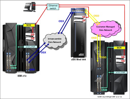
Figure 2-12 IEDN, and client-managed data networks in an ensemble
Optionally, as part of the ensemble, any OSA-Express5S, OSA-Express4S, or OSA-Express3 features (with CHPID type OSD) in z Systems can connect to the client-managed data network. The client-managed network can also be connected to the IEDN TOR switches in the zBX node.
In addition, each BladeCenter chassis in the zBX has two Fibre Channel (FC) switch modules that connect to FC disk storage a SAN switch. Each FC switch supports up to six external FC links to connect to SAN switches.
Figure 2-13 shows front and rear views of a zBX rack (Rack B).

Figure 2-13 zBX rack B front and back configuration
The zBX racks include the following features:
•Two 1U internal Support Elements
•Two KVM (Keyboard-Video-Mouse) SE components
•Two TOR 1000BASE-T switches (rack B only) for the INMN
•Two TOR 10 GbE switches (rack B only) for the IEDN
•Up to two BladeCenter chassis in each rack
Each BladeCenter consists of the following features:
– Up to 14 blade slots
– Two Advanced Management Modules (AMM)
– Two Ethernet Switch Modules (ESM)
– Two 10 GbE high speed switch (HSS) modules
– Two 8 Gbps Fibre Channel switch modules
– Two blower modules
•Power Distribution Units (PDU)
The following blade types are supported in zBX:
•IBM POWER7 PS701 Express blades
•IBM System x blades (HX5 7873 dual-socket 16-core)
•IBM WebSphere DataPower XI50 for zEnterprise blades (double-width)
PowerVM Enterprise Edition is the hypervisor on the POWER7 blades, and the supported operating system is AIX. Linux on System x and Windows on System x are the supported operating systems for select System x blades, using the zBX integrated hypervisor for IBM System x blades (using a Kernel-based virtual machine). Both hypervisors are shipped, serviced, and deployed as z Systems LIC, booted automatically at power-on reset, and are isolated on the internal platform management network.
Client-supplied external disks are required with the zBX. Supported Fibre Channel Protocol (FCP) disk types and vendors with IBM blades are listed at the following web page:
For more information about the number of blades that are supported and configuration options, see the IBM IBM z13 Technical Guide, SG24-8251.
1 Complementary metal-oxide-semiconductor
2 Simultaneous multithreading (SMT): Two simultaneous threads running concomitantly on the same core
3 Single-instruction, multiple-data (SIMD): Vector processing unit (one instruction applied to a vector of data)
4 Symmetric multiprocessing (SMP)
5 MES: miscellaneous equipment specification (upgrade or change)
6 Distances are valid for OM3 cabling.
7 FICON Express8S is offered on new build to support point to point 2 Gbps attachments.
8 Distances are valid for OM3 cabling.
10 Current maximum number of blades supported: 112 POWER7, 28 for DataPower XI50z, 56 for System x HX5
..................Content has been hidden....................
You can't read the all page of ebook, please click here login for view all page.