


Hardware Management Console and Support Elements
The Hardware Management Console (HMC) supports many functions and tasks to extend the management capabilities of the IBM z13 (z13). When tasks are performed on the HMC, the commands are sent to one or more Support Elements (SEs), which then issue commands to their central processor complexes (CPCs) or IBM z BladeCenter Extension (zBX).
This chapter addresses the HMC and SE in general, and adds relevant information for HMCs that manage ensembles with the IBM z Unified Resource Manager.
This chapter includes the following sections:
11.1 Introduction to the HMC and SE
The HMC is a stand-alone computer that runs a set of management applications. The HMC is a closed system, which means that no other applications can be installed on it.
The HMC is used to set up, manage, monitor, and operate one or more z Systems CPCs. It manages z Systems hardware, its logical partitions (LPARs), and provides support applications. At least one HMC is required to operate an IBM z Systems server. An HMC can manage multiple z Systems CPCs and can be at a local or a remote site.
If the z13 is defined as a member of an ensemble, a pair of HMCs is required (a primary and an alternate). When a z13 is defined as a member of an ensemble, certain restrictions apply. For more information, see 11.6, “HMC in an ensemble” on page 446.
The SEs are two integrated servers in the A frame that are supplied together with the z13. One is the primary SE and the other is the alternate SE. The primary SE is the active one. The alternate acts as the backup. The SEs are closed systems, just like the HMCs, and no other applications can be installed on them.
When tasks are performed at the HMC, the commands are routed to the active SE of the z Systems CPC. The SE then issues those commands to their CPC and controlled zBX (if any). One HMC can control up to 100 SEs and one SE can be controlled by up to 32 HMCs.
Some functions are available only on the SE. With Single Object Operations (SOOs), these functions can be used from the HMC. For more information, see “Single object operating” on page 427.
The HMC Remote Support Facility (RSF) provides the important communication to a centralized IBM support network for hardware problem reporting and service. For more information, see 11.4, “Remote Support Facility (RSF)” on page 425.
11.2 HMC and SE enhancements and changes
The z13 comes with the new HMC application Version 2.13.0. Generally, use the “What’s New” task to explore the new features that are available for each release. For a complete list of HMC and SE functions, see the HMC and SE (Version 2.13.0) console help system or go to the IBM Knowledge Center at the following website:
After you get to the IBM Knowledge Center, click z Systems, and then click z13.
Driver 22 HMC and SE enhancements and changes
The HMC and SE with Driver 22 has several enhancements and changes for the z13:
•Rack-mounted HMC
There is a new rack-mounted HMC (FC 0094) that is available. For more information, see 11.2.1, “New rack-mounted HMC” on page 416.
•New SE server
The SEs are no longer two notebooks in one z13. There are now two servers that are installed in the top of the A frame. For more information, see 11.2.2, “New Support Elements” on page 417.
•New backup options
The backup options of the HMC and SE are changed. There now is a different destination for the backup, a new optional 32 GB USB flash memory drive (UFD) that is available for backups. For more information, see 11.2.3, “New backup options of HMCs and primary SEs” on page 417.
•Monitor activity enhancements
You can now display the activity for an LPAR by processor type, and the Monitors Dashboard is enhanced to show simultaneous multithreading (SMT) usage. For more information, see “The Monitors Dashboard task” on page 433.
•HMC Data Replication
If you are using HMC Data Replication and you have an HMC at Driver 22, this HMC can do only Data Replication with another HMC at Driver 22. Data Replication with previous driver levels less than Driver 22 are not supported on an HMC at Driver 22. HMC Data Replication is not available for the primary and alternate Ensemble HMCs when using the IBM zEnterprise Unified Resource Manager because they use mirroring.
•STP enhancements
There are enhancements and changes for the Server Time Protocol (STP), which are described in 11.5.8, “Server Time Protocol (STP) support” on page 436.
•Help infrastructure updates
The content from the following publications is incorporated into the HMC and SE help system:
– z Systems Hardware Management Console Operations Guide Version 2.13.0
– z Systems Hardware Management Console Operations Guide for Ensembles Version 2.13.0
– z Systems Support Element Operations Guide Version 2.13.0
Alternatively, see the HMC and SE (Version 2.13.0) console help system or go to the IBM Knowledge Center at the following website:
After you get to the IBM Knowledge Center, click z Systems, and then click z13.
•Disable boot from removable media
You can disable the boot from removable media on the HMC and SE in the Unified Extensible Firmware Interface (UEFI) and set an admin password for the UEFI (the successor of BIOS). This action protects the SE and HMC against unauthorized booting from removable media. An IBM Service Support Representative (IBM SSR) might perform the following tasks, which require booting from removable media:
– Engineering Change (EC) upgrade
– Save or restore of Save/Restore data
– Hard disk drive (HDD) restore
– HMC preinstallation
|
Note: When you set an UEFI admin password, it is crucial that you can provide it (or temporarily remove the admin password) to the IBM SSR for these tasks.
|
Driver 15 and Driver 22 HMC and SE enhancements and changes
The following enhancements have been available since zEC12 Driver 15:
•Enhanced IBM Service Support System.
If the HMC or SE is at Driver 15 or later, they can use a new remote infrastructure to connect through the RSF for some tasks. This feature might require the customer to change the network settings (proxy, firewall, and so on) for the RSF infrastructure. For more information, see 11.4.2, “RSF connections to IBM and Enhanced IBM Service Support System” on page 426.
•Tasks and panels are updated to support the configuration and management of the new features that were introduced with the zEC12: Flash Express, IBM z Advanced Workload Analysis Reporter (IBM zAware), zEnterprise Data Compression (zEDC) Express, and 10GbE Remote Direct Memory Access over Converged Ethernet (RoCE) Express.
•Updates to x3270 Support (also known as “Secure 3270”).
The “Configure 3270 Emulators” task, on the HMC and Trusted Key Entry (TKE) workstation consoles, is enhanced to verify the authenticity of the certificate that is returned by the 3270 server when a secure and encrypted Secure Sockets Layer (SSL) connection is established to an IBM host. For more information, see “Updates to x3270 support” on page 429.
•Audit log changes.
The RSF security events are moved from security logs to the audit logs. The SSL connection information is logged, including the host name, host name on the certificate, and the cipher that is used.
•Default HMC user IDs.
It is no longer possible to change the “Managed Resource” or “Task Roles” of the default user IDs operator, advanced, sysprog, acsadmin, and service. If you want the ability to change the roles for a default user ID, create your own version by copying an existing default user ID.
•Open Systems Adapter Support Facility (OSA/SF) available on the HMC
The OSA/SF is a component of z/OS, z/VM, and z/VSE.
The “OSA Advanced Facilities” task on the HMC is enhanced to provide configuration, validation, activation, and display support exclusively for the OSA-Express5S and OSA-Express4S features.
OSA/SF on the HMC is required for the OSA-Express5S feature. Either OSA/SF on the HMC or the OSA/SF in the operating system component can be used for the OSA-Express4S features.
For more information, see OSA/SF on the Hardware Management Console, SC14-7580.
•Defined capacity of LPARs (absolute physical HW LPAR capacity setting).
Driver 15 introduced the ability to define, in the image profile for shared processors, the absolute processor capacity that the image can use (independent of partition weight or other cappings). To indicate that the LPAR can use the undedicated processors absolute capping, select Absolute capping on the Image Profile Processor settings to specify an absolute number of processors to cap the LPAR’s activity. The absolute capping value can either be “None” or a value for the number of processors (0.01 - 255.0 can be specified).
•Server Time Protocol (STP): Improved SE time accuracy before initial microcode load (IML).
If the CPC has not run the IML, the SE sets the time by using the external time source (ETS) every hour if the Network Time Protocol (NTP) servers are configured in the ETS Configuration tab in the “System (Sysplex) Time” task. This configuration helps to ensure that the SE time is accurate before the IML, which is also known as the power-on reset (POR).
•STP NTP broadband security.
Authentication is added to the HMC NTP communication with NTP time servers. For more information, see “HMC NTP broadband authentication support” on page 440
•The environmental task has usability improvements regarding the time frame. For more information, see “Environmental Efficiency Statistics task” on page 435.
•Crypto Function integration in the Monitors Dashboard.
For more information, see “The Monitors Dashboard task” on page 433.
•Removal of modem support from the HMC.
This change affects customers that use modems for RSF or for STP NTP access. For more information, see 11.4, “Remote Support Facility (RSF)” on page 425 and 11.5.9, “NTP client and server support on the HMC” on page 440.
•Installation and activation by maintenance change level (MCL) bundle target.
For more information, see “Microcode installation by MCL bundle target” on page 432.
•A confirmation panel before processing an Alt-Ctrl-Delete request is added.
|
Note: If an HMC must be rebooted, always use the Shutdown and Restart task on the HMC to avoid any file corruption.
|
•It is possible to allow the mass deletion of messages from the Operating System Messages task.
•The Network Settings task is updated to show the ordering of the routing table entries.
•zBX firmware management.
As a result of a MES upgrade from a zBX Model 002 or zBX Model 003, the zBX Model 004 becomes a stand-alone box and can be added to an existing ensemble HMC as an ensemble node member. As part of the upgrade, the zBX Model 004 is detached from the owning CPC and receives two redundant internal SEs that are installed on its B Frame. The zBX Model 004 object can then be added to the ensemble HMC by using the Add Object Definition task. The ensemble HMC and the zBX Model 004 SE along with the zEnterprise Unified Resource Manager can perform the following monitoring and management functions:
– zBX firmware upgrades are downloaded from IBM RETAIN® by using the HMC broadband RSF connection. Firmware updates are saved locally and installed during a scheduled MCL apply session.
– Firmware updates are installed from the HMC and zBX SEs by using the same process and controls that are used for z Systems.
– zBX hardware-related and firmware-related failures are reported to IBM, and the IBM support structure is engaged, by using the HMC RSF. This is the same process that is used for reporting z Systems problems.
•zBX lifecycle management: zBX Model 004 supports the same System x, POWER7, and DataPower XI50z blade types that are supported in zBX Model 003 and zBX Model 002.
11.2.1 New rack-mounted HMC
Feature code (FC) 0094 provides a rack-mounted HMC for a z13. It cannot be ordered as a feature code for zEC12, zBC12, or previous z Systems.
The HMC is an 1U IBM System x server and comes with an IBM 1U standard console. The system unit and tray must be mounted in the rack in two adjacent 1U locations in the “ergonomic zone” between 21U and 26U.
The customer must provide the rack. Three C13 power receptacles are required: Two for the system unit and one for the display and keyboard, as shown in Figure 11-1.
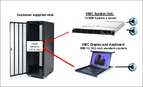
Figure 11-1 Rack-mounted HMC
11.2.2 New Support Elements
The SEs are no longer two notebooks in one z13. They are now two servers that are installed at the top of the A frame. They are managed by the keyboards, mice, and displays that are mounted in the front and rear of the tray of the Z frame (where the SE notebooks were in previous z Systems), as shown in Figure 11-2 on page 417. The SEs have internal USB attached smart card readers to support Flash Express and Feature on Demand (FoD).

Figure 11-2 SEs location
11.2.3 New backup options of HMCs and primary SEs
This section provides a short description of the new backup options that are available for HMC Version 2.13.0.
Backup of primary SEs or HMCs to an FTP server
With Driver 22, you can do a backup of primary SEs or HMCs to an FTP server.
|
Note: If you do a backup to an FTP server for a z13 or zBX Model 004, ensure that you have set up a connection to the FTP server by using the Configure Backup Setting task. If you have not set up a connection to the FTP server, a message appears that prompts you to configure your FTP server.
|
The FTP server must be supplied by the customer. You can enable a secure FTP connection to your server.
Figure 11-3 shows the window where you can configure your backup FTP server.

Figure 11-3 Configure backup FTP server
Backup of HMCs
A backup of the HMC can be done to the following media
•A USB flash memory drive (UFD)
•An FTP server
•A UFD and FTP server
Figure 11-4 shows the destination options of the HMCA: Backup Critical Console Data task.

Figure 11-4 Backup Critical Console Data destinations
FC 0848
A new, optional 32 GB UFD is available for backups. The standard is an 8 GB UFD. The 32 GB UFD helps you to avoid backup problems if you are using IBM zEnterprise Unified Resource Manager, zBX, IBM zAware, several previous z Systems SE backups, and so on.
Backup of primary SEs
The backup for the primary SE of a z13 or zBX Model 004 can be made to the following media:
•The primary SE HDD and alternate SE HDD
•The primary SE HDD and alternate SE HDD and FTP server
It is no longer possible to do the primary SE backup to a UFD of a z13 or zBX Model 004 SE. The backup of a primary SE of zEC12, zBC12, z114, z196, z10 BC, z9 BC, and z9 EC can be saved only to a UFD.
Figure 11-5 shows examples of the different destination options of the SE Backup Critical Data for different CPC machine types.

Figure 11-5 Backup Critical Data destinations of SEs
For more information, see the HMC and SE (Version 2.13.0) console help system or go to the IBM Knowledge Center at the following link:
After you get to the IBM Knowledge Center, click z Systems, and then click z13.
Scheduled operations for the backup of HMCs and SEs
The Scheduled Operation task with the new backup options for HMC is changed, as shown in Figure 11-6.

Figure 11-6 Scheduled Operation for HMC backup
The Scheduled Operation task with the new backup options for the SEs is changed, as shown in Figure 11-7.

Figure 11-7 Scheduled Operation for SEs backup
11.2.4 SE driver support with the HMC driver
The driver of the HMC and SE is equivalent to a specific HMC and SE version, as shown in these examples:
•Driver 22 is equivalent to Version 2.13.0
•Driver 86 is equivalent to Version 2.11.0
•Driver 79 is equivalent to Version 2.10.2
An HMC with Version 2.13.0 can support different z Systems types. Some functions that are available on Version 2.13.0 and later are supported only when the HMC is connected to a z13 with Version 2.13.0.
Table 11-1 shows a summary of the SE drivers and versions that are supported by the new HMC Version 2.13.0 (Driver 22).
Table 11-1 z13 HMC at Driver 22 - z Systems support summary
|
z Systems family name
|
Machine type
|
SE driver
|
SE version
|
Ensemble node potential
|
|
z13
|
2964
|
22
|
2.13.0
|
Yes
|
|
zBX Node
|
2458 Model 004
|
22
|
2.13.0
|
Required
|
|
zBC12
|
2828
|
15
|
2.12.1
|
Yes
|
|
zEC12
|
2827
|
15
|
2.12.1
|
Yes
|
|
z114
|
2818
|
93
|
2.11.1
|
Yes
|
|
z196
|
2817
|
93
|
2.11.1
|
Yes
|
|
z10 BC
|
2098
|
79
|
2.10.2
|
No
|
|
z10 EC
|
2097
|
79
|
2.10.2
|
No
|
|
z9 BC
|
2096
|
67
|
2.9.2
|
No
|
|
z9 EC
|
2094
|
67
|
2.9.2
|
No
|
|
Note: z900/z800 (Driver 3G, SE Version 1.7.3) and z990/z890 (Driver 55, SE Version 1.8.2) systems are no longer supported. If you have these older systems, they should be managed by separate HMCs running older drivers.
|
11.2.5 HMC feature codes
HMCs that are older than FC 0091 are not supported for the z13 at Driver 22.
FC 0091
FC 0091 can be carried forward, but an HMC for the z13 needs 16 GB of memory. Some FC 0091 features that shipped with previous z Systems have only 8 GB of memory. When
Driver 22 is ordered for an existing FC 0091 HMC, the additional 8 GB of memory is provided if this HMC has only 8 GB of memory.
Driver 22 is ordered for an existing FC 0091 HMC, the additional 8 GB of memory is provided if this HMC has only 8 GB of memory.
FC 0092
FC 0092 is an HMC that contains 16 GB of memory. It is a tower model. The physical dimensions from FC 0092 compared to FC 0090 and FC 0091 are similar, except the depth for FC 0092 is in round numbers, that is, 95 mm (3.75 in.) more.
FC 0094
FC 0094 is the new rack-mounted HMC. It contains 16 GB of memory. For more information, see 11.2.1, “New rack-mounted HMC” on page 416.
11.2.6 Tree Style User Interface and Classic Style User Interface
Two user interface styles are provided with an HMC. The Tree Style User Interface (default) uses a hierarchical model that is common in newer operating systems, and features context-based task launching. The Classic Style User Interface uses the drag-and-drop interface style.
|
Statements of Direction1:
Removal of support for Classic Style User Interface on the Hardware Management Console and Support Element: The IBM z13 will be the last z Systems server to support Classic Style User Interface. In the future, user interface enhancements will be focused on the Tree Style User Interface.
Removal of support for the Hardware Management Console Common Infrastructure Model (CIM) Management Interface: IBM z13 will be the last z Systems server to support the Hardware Console CIM Management Interface. The Hardware Management Console Simple Network Management Protocol (SNMP), and Web Services application programming interfaces (APIs) will continue to be supported.
|
1 All statements regarding IBM plans, directions, and intent are subject to change or withdrawal without notice. Any reliance on these statements of general direction is at the relying party’s sole risk and will not create liability or obligation for IBM.
No Classic Style User Interface is available on zBX Model 004 SEs.
|
Tutorials: IBM Resource Link1 provides tutorials that demonstrate how to change from the Classic Style User Interface to the Tree Style Interface, and introduce the function of the Tree Style Interface on the HMC. You can find Resource Link at the following website:
After you go to the Resource Link website, click Education → IBM z13 → Course Z121-0255-00.
|
1 Registration is required to access IBM Resource Link.
11.3 HMC and SE connectivity
The HMC has two Ethernet adapters, which are supported by HMC Driver 22 for connectivity to up to two different Ethernet LANs.
The SEs on the z13 are connected to the System Control Hubs (SCH). In previous z Systems, the SCH was called the Bulk Power Hub (BPH). The HMC to SCH communication is only possible through an Ethernet switch. Other z Systems servers and HMCs also can be connected to the switch. To provide redundancy, install two Ethernet switches.
Only the switch (and not the HMC directly) can be connected to the SCH.
Figure 11-8 shows the connectivity between HMCs and the SEs.

Figure 11-8 HMC to SE connectivity
Various methods are available for setting up the network. It is your responsibility to plan and design the HMC and SE connectivity. Select the method based on your connectivity and security requirements.
|
Security: Configuration of network components, such as routers or firewall rules, is beyond the scope of this book. Whenever the networks are interconnected, security exposures can exist. For more information about HMC security, see Integrating the Hardware Management Console‘s Broadband Remote Support Facility into your Enterprise, SC28-6927. It is available at the IBM Resource Link.1
For more information about the HMC settings that are related to access and security, see the HMC and SE (Version 2.13.0) console help system or go to the IBM Knowledge Center at the following link:
After you get to the IBM Knowledge Center, click z Systems, and then click z13.
|
1 Registration is required to access IBM Resource Link.
Network planning for the HMC and SE
Plan the HMC and SE network connectivity carefully to allow for current and future use. Many of the z Systems capabilities benefit from the various network connectivity options that are available.
For example, these functions, which depend on the HMC connectivity, are available to the HMC:
•Lightweight Directory Access Protocol (LDAP) support, which can be used for HMC user authentication
•NTP client/server support
•RSF through broadband
•HMC access through a remote web browser
•Enablement of the SNMP and Common Information Model APIs to support automation or management applications, such as IBM System Director Active Energy Manager (AEM)
These examples are shown in Figure 11-9.

Figure 11-9 HMC connectivity examples
For more information, see the following resources:
•The HMC and SE (Version 2.13.0) console help system, or go to the IBM Knowledge Center at the following link:
After you get to the IBM Knowledge Center, click z Systems, and then click z13.
•IBM z13 Installation Manual for Physical Planning, GC28-6938
11.3.1 Hardware prerequisite changes
The following HMC changes are important for the z13:
No HMC LAN switches can be ordered from IBM
You can no longer order the Ethernet switches that are required by the HMCs to connect to the z13. You must provide them yourself. Existing supported switches can still be used.
Ethernet switches/hubs typically have these characteristics:
•Sixteen auto-negotiation ports
•10/100/1000 Mbps data rate
•Full or half duplex operation
•Auto-medium-dependent interface crossover (MDIX) on all ports
•Port status LEDs
RSF is broadband-only
RSF through a modem is not supported on the z13 HMC. Broadband is needed for hardware problem reporting and service. For more information, see 11.4, “Remote Support Facility (RSF)” on page 425.
11.3.2 TCP/IP Version 6 on the HMC and SE
The HMC and SE can communicate by using IPv4, IPv6, or both. Assigning a static IP address to an SE is unnecessary if the SE communicates only with HMCs on the same subnet. The HMC and SE can use IPv6 link-local addresses to communicate with each other.
IPv6 link-local addresses have the following characteristics:
•Every IPv6 network interface is assigned a link-local IP address.
•A link-local address is used only on a single link (subnet) and is never routed.
•Two IPv6-capable hosts on a subnet can communicate by using link-local addresses, without having any other IP addresses assigned.
11.3.3 Assigning addresses to the HMC and SE
An HMC can have the following IP configurations:
•Statically assigned IPv4 or statically assigned IPv6 addresses
•Dynamic Host Configuration Protocol (DHCP)-assigned IPv4 or DHCP-assigned IPv6 addressees
•Auto-configured IPv6:
– Link-local is assigned to every network interface.
– Router-advertised, which is broadcast from the router, can be combined with a Media Access Control (MAC) address to create a unique address.
– Privacy extensions can be enabled for these addresses as a way to avoid using the MAC address as part of the address to ensure uniqueness.
An SE can have the following IP addresses:
•Statically assigned IPv4 or statically assigned IPv6
•Auto-configured IPv6 as link-local or router-advertised
IP addresses on the SE cannot be dynamically assigned through DHCP to ensure repeatable address assignments. Privacy extensions are not used.
The HMC uses IPv4 and IPv6 multicasting1 to discover automatically SEs. The HMC Network Diagnostic Information task can be used to identify the IP addresses (IPv4 and IPv6) that are being used by the HMC to communicate to the CPC SEs.
IPv6 addresses are easily identified. A fully qualified IPV6 address has 16 bytes. It is written as eight 16-bit hexadecimal blocks that are separated by colons, as shown in the following example:
2001:0db8:0000:0000:0202:b3ff:fe1e:8329
Because many IPv6 addresses are not fully qualified, shorthand notation can be used. In shorthand notation, the leading zeros can be omitted, and a series of consecutive zeros can be replaced with a double colon. The address in the previous example also can be written in the following manner:
2001:db8::202:b3ff:fe1e:8329
For remote operations that use a web browser, if an IPv6 address is assigned to the HMC, navigate to it by specifying that address. The address must be surrounded with square brackets in the browser’s address field:
https://[fdab:1b89:fc07:1:201:6cff:fe72:ba7c]
Using link-local addresses must be supported by browsers.
11.4 Remote Support Facility (RSF)
The HMC RSF provides important communication to a centralized IBM support network for hardware problem reporting and service. The following types of communication are provided:
•Problem reporting and repair data
•Microcode Change Level (MCL) delivery
•Hardware inventory data, which is also known as vital product data (VPD)
•On-demand enablement
|
Consideration: RSF through a modem is not supported on the z13 HMC. Broadband connectivity is needed for hardware problem reporting and service. Modems on installed HMC FC 0091 hardware do not work with HMC Version 2.13.0, which is required to support the z13.
|
11.4.1 Security characteristics
The following security characteristics are in effect:
•RSF requests always are initiated from the HMC to IBM. An inbound connection is never initiated from the IBM Service Support System.
•All data that is transferred between the HMC and the IBM Service Support System is encrypted with high-grade Secure Sockets Layer (SSL)/Transport Layer Security (TLS) encryption.
•When starting the SSL/TLS-encrypted connection, the HMC validates the trusted host with the digital signature that is issued for the IBM Service Support System.
•Data that is sent to the IBM Service Support System consists of hardware problems and configuration data.
|
Additional resource: For more information about the benefits of Broadband RSF and the SSL/TLS-secured protocol, and a sample configuration for the Broadband RSF connection, go the IBM Resource Link1 at the following website:
When you reach the Resource Link, click Library → IBM z13 and then select the book Integrating the HMC Broadband Remote Support Facility into Your Enterprise, SC28-6927.
|
1 Registration is required to access IBM Resource Link.
11.4.2 RSF connections to IBM and Enhanced IBM Service Support System
If the HMC and SE are at Driver 22, the driver uses a new remote infrastructure at IBM when the HMC connects through RSF for certain tasks. Check your network infrastructure settings to ensure that this new infrastructure will work.
At the time of writing, RSF still uses the “traditional” RETAIN connection. You must add access to the new Enhanced IBM Service Support System to your current RSF infrastructure (proxy, firewall, and so on).
To have the best availability and redundancy and to be prepared for the future, the HMC must have access to the Internet to IBM through RSF in the following manner.
Transmission to the enhanced IBM Support System requires a domain name server (DNS). The DNS must be configured on the HMC if you are not using a proxy for RFS. If you are using a proxy for RSF, the proxy must provide the DNS.
The following host names and IP addresses are used and your network infrastructure must allow the HMC to have access to the following host names or IP addresses:
•Host names:
– www-945.ibm.com on port 443
– esupport.ibm.com on port 443
•IP addresses. IPv4, IPv6, or both can be used:
– IPv4:
• 129.42.26.224:443
• 129.42.34.224:443
• 129.42.42.224:443
• 129.42.56.129:443
• 129.42.58.129:443
• 129.42.60.129:443
• 129.42.50.224:443
• 129.42.54.129:443
– IPv6:
• 2620:0:6C0:1::1000:443
• 2630:0:6C1:1::1000:443
• 2630:0:6C2:1::1000:443
• 2620:0:6C4:1::1000:443
• 2620:0:6C4:200:129:42:60:189:443
• 2620:0:6C0:200:129:42:60:189:443
• 2630:0:6C1:200:129:42:60:189:443
• 2630:0:6C2:200:129:42:60:189:443
|
Note: All other previous existing IP addresses are no longer supported.
|
11.4.3 HMC and SE remote operations
There are two ways to perform remote manual operations on the HMC:
•Using a remote HMC
A remote HMC is a physical HMC that is on a different subnet from the SE. This configuration prevents the SE from being automatically discovered with IP multicast. A remote HMC requires TCP/IP connectivity to each SE to be managed. Therefore, any existing customer-installed firewalls between the remote HMC and its managed objects must permit communications between the HMC and the SE. For service and support, the remote HMC also requires connectivity to IBM, or to another HMC with connectivity to IBM through RSF. For more information, see 11.4, “Remote Support Facility (RSF)” on page 425.
•Using a web browser to connect to an HMC
The z13 HMC application simultaneously supports one local user and any number of remote users. The user interface in the web browser is the same as the local HMC and has the same functions. Some functions are not available. Access by the UFD requires physical access to the HMC. Logon security for a web browser is provided by the local HMC user logon procedures. Certificates for secure communications are provided, and can be changed by the user. A remote browser session to the primary HMC that is managing an ensemble allows a user to perform ensemble-related actions.
Microsoft Internet Explorer, Mozilla Firefox, and Goggle Chrome were tested as remote browsers. For detailed web browser requirements, see the HMC and SE (Version 2.13.0) console help system or go to the IBM Knowledge Center at the following link:
After you get to the IBM Knowledge Center, click z Systems, and then click z13.
Single object operating
It is not necessary to be physically close to an SE to use it. The HMC can be used to access the SE remotely by using the Single Object Operation (SOO). The interface is the same as the one on the SE. For more information, see the HMC and SE (Version 2.13.0) console help system or go to the IBM Knowledge Center at the following link:
After you get to the IBM Knowledge Center, click z Systems, and then click z13.
11.5 HMC and SE key capabilities
The HMC and SE have many capabilities. This section covers the key areas. For a complete list of capabilities, see the HMC and SE (Version 2.13.0) console help system or go to the IBM Knowledge Center at the following link:
After you get to the IBM Knowledge Center, click z Systems, and then click z13.
11.5.1 Central processor complex (CPC) management
The HMC is the primary place for CPC control. For example, the input/output configuration data set (IOCDS) contains definitions of LPARs, channel subsystems, control units, and devices, and their accessibility from LPARs. IOCDS can be created and put into production from the HMC.
The HMC is used to start the power-on reset (POR) of the server. During the POR, processor units (PUs) are characterized and placed into their respective pools, memory is put into a single storage pool, and the IOCDS is loaded and initialized into the hardware system area (HSA).
The Hardware messages task displays hardware-related messages at the CPC level, LPAR level, or SE level. It also displays hardware messages that relate to the HMC itself.
11.5.2 Logical partition management
Use the HMC to define LPAR properties, such as the number of processors of each type, how many are reserved, or how much memory is assigned to it. These parameters are defined in LPAR profiles, and are stored on the SE.
Because Processor Resource/Systems Manager (PR/SM) must manage LPAR access to processors and the initial weights of each partition, weights are used to prioritize partition access to processors.
You can use the Load task on the HMC to perform an IPL of an operating system. This task causes a program to be read from a designated device, and starts that program. You can perform the IPL of the operating system from storage, the HMC DVD-RAM drive, the USB flash memory drive (UFD), or a File Transfer Protocol (FTP) server.
When an LPAR is active and an operating system is running in it, you can use the HMC to dynamically change certain LPAR parameters. The HMC provides an interface to change partition weights, add logical processors to partitions, and add memory.
LPAR weights can also be changed through a scheduled operation. Use the Customize Scheduled Operations task to define the weights that are set to LPARs at the scheduled time.
Channel paths can be dynamically configured on and off, as needed for each partition, from an HMC.
The Change LPAR Controls task for the z13 can export the Change LPAR Controls table data to a comma-separated value (.csv)-formatted file. This support is available to a user when connected to the HMC remotely by a web browser.
Partition capping values can be scheduled and are specified on the Change LPAR Controls scheduled operation support. Viewing details about an existing Change LPAR Controls scheduled operation is available on the SE.
Absolute physical HW LPAR capacity setting
Driver 15 introduced the capability to define, in the image profile for shared processors, the absolute processor capacity that the image is allowed to use (independent of the image weight or other cappings).
To indicate that the LPAR can use the undedicated processors absolute capping, select Absolute capping on the Image Profile Processor settings to specify an absolute number of processors to cap the LPAR’s activity. The absolute capping value can either be “None” or a value for the number of processors (0.01 - 255.0).
11.5.3 Operating system communication
The Operating System Messages task displays messages from an LPAR. You also can enter operating system commands and interact with the system. This task is especially valuable for entering Coupling Facility Control Code (CFCC) commands.
The HMC also provides integrated 3270 and ASCII consoles. These consoles allow an operating system to be accessed without requiring other network or network devices, such as TCP/IP or control units.
Updates to x3270 support
The Configure 3270 Emulators task on the HMC and TKE consoles was enhanced with Driver 15 to verify the authenticity of the certificate that is returned by the 3270 server when a secure and encrypted SSL connection is established to an IBM host. This is also known as Secure 3270.
Use the Certificate Management task if the certificates that are returned by the 3270 server are not signed by a well-known trusted certificate authority (CA) certificate, such as VeriSign or Geotrust. An advanced action within the Certificate Management task, Manage Trusted Signing Certificates, is used to add trusted signing certificates.
For example, if the certificate that is associated with the 3270 server on the IBM host is signed and issued by a corporate certificate, it must be imported, as shown in Figure 11-10.

Figure 11-10 Manage Trusted Signing Certificates
If the connection between the console and the IBM host can be trusted at the time of importing the certificate, the import from the remote server option can be used, as shown in Figure 11-11. Otherwise, import the certificate from removable media.

Figure 11-11 Import Remote Certificate example
A secure Telnet connection is established by adding the prefix L: to the IP address:port of the IBM host, as shown in Figure 11-12.
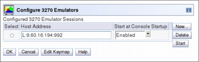
Figure 11-12 Configure 3270 Emulators
11.5.4 HMC and SE microcode
The microcode for the HMC, SE, CPC, and zBX is included in the driver/version. The HMC provides the management of the driver upgrade through Enhanced Driver Maintenance (EDM). EDM also provides the installation of the latest functions and the patches (Microcode Change Levels (MCLs)) of the new driver.
When you perform a driver upgrade, always check the Driver xx Customer Exception Letter option in the Fixes section at the IBM Resource Link.
For more information, see 9.9, “z13 Enhanced Driver Maintenance (EDM)” on page 372.
Microcode Change Level (MCL)
Regular installation of MCLs is key for reliability, availability, and serviceability (RAS), optimal performance, and new functions:
•Install MCLs on a quarterly basis at a minimum.
•Review hiper MCLs continuously to decide whether to wait for the next scheduled fix application session or to schedule one earlier if the risk assessment warrants.
|
Tip: The IBM Resource Link1 provides access to the system information for your z Systems according to the system availability data that is sent on a scheduled basis. It provides more information about the MCL status of your z13. To access the Resource Link, to the following website:
After you reach the Resource Link, click Tools → Machine Information, choose your z Systems server, and click EC/MCL.
|
1 Registration is required to access the IBM Resource Link.
Microcode terms
The microcode has these characteristics:
•The driver contains engineering change (EC) streams.
•Each EC stream covers the code for a specific component of the of the z13. It has a specific name and an ascending number.
•The EC stream name and a specific number are one MCL.
•MCLs from the same EC stream must be installed in sequence.
•MCLs can have installation dependencies on other MCLs.
•Combined MCLs from one or more EC streams are in one bundle.
•An MCL contains one or more Microcode Fixes (MCFs).
Figure 11-13 shows how the driver, bundle, EC stream, MCL, and MCFs interact with each other.

Figure 11-13 Microcode terms and interaction
Microcode installation by MCL bundle target
A bundle is a set of MCLs grouped during testing and released as a group on the same date. You can install an MCL to a specific target bundle level. The System Information window is enhanced to show a summary bundle level for the activated level, as shown in Figure 11-14.

Figure 11-14 System Information - Bundle level
11.5.5 Monitoring
This section addresses monitoring considerations.
Monitor task group
The Monitor task group on the HMC and SE includes monitoring-related tasks for the z13, as shown in Figure 11-15.
Figure 11-15 HMC Monitor Task Group
The Monitors Dashboard task
The Monitors Dashboard task supersedes the System Activity Display (SAD). In the z13, the Monitors Dashboard task in the Monitor task group provides a tree-based view of resources. Multiple graphical views exist for displaying data, including history charts. The Open Activity task, which is known as SAD, monitors processor and channel usage. It produces data that includes power monitoring information, power consumption, and the air input temperature for the server.
Figure 11-16 shows an example of the Monitors Dashboard task.

Figure 11-16 Monitors Dashboard task
Starting with Driver 22, you can display the activity for an LPAR by processor type, as shown in Figure 11-17.

Figure 11-17 Display the activity for an LPAR by processor type
The Monitors Dashboard is enhanced to show simultaneous multithreading (SMT) usage, as shown in the example in Figure 11-18.

Figure 11-18 Display the SMT usage
The crypto-utilization percentage is displayed on the Monitors Dashboard according to the physical channel ID (PCHID) number. The associated crypto number (Adjunct Processor Number) for this PCHID is also shown in the table. It provides information about the usage rate on a system-wide basis, not per LPAR, as shown in Figure 11-19.

Figure 11-19 Monitors Dashboard - crypto function integration
For Flash Express, a new window is added, as shown in Figure 11-20.

Figure 11-20 Monitors Dashboard - Flash Express function integration
Environmental Efficiency Statistics task
The Environmental Efficiency Statistics task (Figure 11-21) is part of the Monitor task group. It provides historical power consumption and thermal information for the zEnterprise CPC, and is available on the HMC.
The data is presented in table format and graphical “histogram” format. The data also can be exported to a .csv-formatted file so that the data can be imported into a spreadsheet. For this task, you must use a web browser to connect to an HMC.

Figure 11-21 Environmental Efficiency Statistics
11.5.6 Capacity on demand (CoD) support
All CoD upgrades are performed using the SE Perform a Model Conversion task. Use the task to retrieve and activate a permanent upgrade, and to retrieve, install, activate, and deactivate a temporary upgrade. The task shows a list of all installed or staged LIC configuration code (LICCC) records to help you manage them. It also shows a history of recorded activities.
The HMC for IBM z13 has these CoD capabilities:
•SNMP API support:
– API interfaces for granular activation and deactivation
– API interfaces for enhanced CoD query information
– API event notification for any CoD change activity on the system
– CoD API interfaces, such as On/Off CoD and Capacity BackUp (CBU)
•SE panel features (accessed through HMC Single Object Operations):
– Panel controls for granular activation and deactivation
– History panel for all CoD actions
– Description editing of CoD records
•HMC/SE Version 2.13.0 provides the following CoD information:
– Millions of service units (MSU) and processor tokens
– Last activation time
– Pending resources that are shown by processor type instead of only a total count
– Option to show the details of installed and staged permanent records
– More details for the Attention state by providing seven more flags
HMC and SE are a part of the z/OS Capacity Provisioning environment. The Capacity Provisioning Manager (CPM) communicates with the HMC through z Systems APIs, and enters CoD requests. For this reason, SNMP must be configured and enabled by using the Customize API Settings task on the HMC.
For more information about using and setting up CPM, see these publications:
•z/OS MVS™ Capacity Provisioning User’s Guide, SC33-8299
•z Systems System Capacity on Demand User’s Guide, SC28-6943
11.5.7 Features on Demand (FoD) support
FoD is a new centralized way to entitle flexibly features and functions on the system. FoD contains, for example, the zBX High Water Marks (HWMs). HWMs refer to highest quantity of blade entitlements by blade type that the customer has purchased. On the z196/z114, the zBX HWMs are stored in the processor and memory LICCC record. On the z13, they are in the Feature on Demand record.
FoD allows separate LICCC controls for z Systems processors (central processors (CPs), Integrated Facility for Linux (IFL) and IBM System z Integrated Information Processors (zIIPs)), and zBX HWMs, providing entitlement controls for each blade type. It is also used as LICCC support for the following features:
•zAware: Enablement/max connections
•Base/proprietary service: Expiration date
•New features: Yet to be announced or developed
11.5.8 Server Time Protocol (STP) support
With the STP functions, the role of the HMC is extended to provide the user interface for managing the Coordinated Timing Network (CTN):
•The z13 relies solely on STP for time synchronization, and continues to provide support of a pulse per second (PPS) port. It maintains accuracy of 10 microseconds as measured at the PPS input of the z13 server. If STP uses an NTP server without PPS, a time accuracy of 100 milliseconds to the ETS is maintained.
•The z13 cannot be in the same CTN with a System z10 (n-2) or earlier systems. As a consequence, the z13 cannot become member of an STP mixed CTN.
•An STP-only CTN can be managed by using different HMCs. However, the HMC must be at the same Driver level (or later) than any SE that is to be managed. Furthermore, all SEs to be managed must be known (defined) to that HMC.
In an STP-only CTN, the HMC can be used to perform the following tasks:
•Initialize or modify the CTN ID.
•Initialize the time, manually or by contacting an NTP server.
•Initialize the time zone offset, Daylight Saving Time offset, and leap second offset.
•Assign the roles of preferred, backup, and current time servers, and arbiter.
•Adjust time by up to plus or minus 60 seconds.
•Schedule changes to the offsets listed. STP can automatically schedule Daylight Saving Time, based on the selected time zone.
•Monitor the status of the CTN.
•Monitor the status of the coupling links that are initialized for STP message exchanges.
•For diagnostic purposes, the Pulse per Second port state on a z13 can be displayed and fenced ports can be reset individually.
STP panel enhancements
The z13 STP panels are enhanced to show the following additional or enhanced information:
•The new ICA adapters are added to the list of possible STP-supporting Coupling Links.
•A new task role is added within the Customize User Controls panel that allows the enablement of the View System (Sysplex) Time option. This option provides view-only access to the STP panels for each individual user role.
•The Initialize Time panel shows the current values of leap second offset, time zone, and ‘date and time’ if the CTN time was set before.
•Set Date and Time is modified so that Use External Time Source (ETS) is the first option. This configuration should encourage the user to select the NTP option (if their system is configured for NTP) because a NTP-set time is more precise compared to a user-set time.
•With Driver 22 and later, the HMC Enable for time synchronization task was moved from the “Add (or Modify) object definition” panel to the Customize Console Date and Time panel. This function synchronizes the HMCs date and time to either an NTP server (if defined) or to a SE Date and Time, with the NTP server option provided as the first choice.
As shown in Figure 11-22, the NTP option is the recommended option, if an NTP server is available. If an NTP server is not available for this HMC, any defined CPC SE can be selected after you select Selected CPCs.

Figure 11-22 Customize Console Date and Time
•The Timing Network panel now includes the next scheduled Daylight Saving Time change and the next leap second adjustment, as shown in Figure 11-23. The schedules that are shown are the ones for the next DLS change (either given per automatic or scheduled adjustment) and for the next Leap Second change (given per scheduled adjustment).
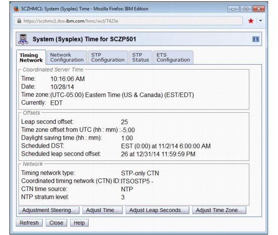
Figure 11-23 Timing Network panel showing ‘Scheduled DST’ and ‘Scheduled leap second offset’
|
Attention: Figure 11-23 shows a ‘Schedule leap second offset’ change to 26 seconds that is scheduled for 12/31/2014. This is not a real leap second that is released by the International Earth Rotation and Reference System Services; It temporarily set only to show the panel appearance.
|
STP recovery is enhanced since zEnterprise. For more information, see “STP recovery enhancement” on page 176.
For more planning and setup information, see the following publications:
•Server Time Protocol Planning Guide, SG24-7280
•Server Time Protocol Implementation Guide, SG24-7281
•Server Time Protocol Recovery Guide, SG24-7380
11.5.9 NTP client and server support on the HMC
The NTP client support allows an STP-only CTN to use an NTP server as an ETS.
This capability addresses the following requirements:
•Clients that want time accuracy for the STP-only CTN
•Clients that use a common time reference across heterogeneous systems
The NTP server becomes the single time source, the ETS, for STP and other servers that are not z Systems (such as AIX, Microsoft Windows, and others) that have NTP clients.
The HMC can act as an NTP server. With this support, the z13 can get time from the HMC without accessing a LAN other than the HMC/SE network. When the HMC is used as an NTP server, it can be configured to get the NTP source from the Internet. For this type of configuration, a LAN that is separate from the HMC/SE LAN can be used.
HMC NTP broadband authentication support
HMC NTP authentication can be used since HMC Driver 15. The SE NTP support is unchanged. To use this option on the SE, configure the HMC with this option as an NTP server for the SE.
Authentication support with a proxy
Some client configurations use a proxy for external access outside the corporate data center. NTP requests are User Datagram Protocol (UDP) socket packets and cannot pass through the proxy. The proxy must be configured as an NTP server to get to target servers on the web. Authentication can be set up on the client’s proxy to communicate with the target time sources.
Authentication support with a firewall
If you use a firewall, HMC NTP requests can pass through it. Use HMC authentication to ensure untampered time stamps.
NTP symmetric key and autokey authentication
With symmetric key and autokey authentication, the highest level of NTP security is available. HMC Level 2.12.0 and later provide windows that accept and generate key information to be configured into the HMC NTP configuration. They can also issue NTP commands, as shown in Figure 11-24.

Figure 11-24 HMC NTP broadband authentication support
The HMC offers symmetric key and autokey authentication and NTP commands:
•Symmetric key (NTP V3-V4) authentication
Symmetric key authentication is described in RFC 1305, which was made available in NTP Version 3. Symmetric key encryption uses the same key for both encryption and decryption. Users exchanging data keep this key to themselves. Messages encrypted with a secret key can be decrypted only with the same secret key. Symmetric key authentication supports network address translation (NAT).
•Symmetric key autokey (NTP V4) authentication
This autokey uses public key cryptography, as described in RFC 5906, which was made available in NTP Version 4. You can generate keys for the HMC NTP by clicking Generate Local Host Key in the Autokey Configuration window. This option issues the ntp-keygen command to generate the specific key and certificate for this system. Autokey authentication is not available with the NAT firewall.
•Issue NTP commands
NTP command support is added to display the status of remote NTP servers and the current NTP server (HMC).
For more information about planning and setup for STP and NTP, see the following publications:
•Server Time Protocol Planning Guide, SG24-7280
•Server Time Protocol Implementation Guide, SG24-7281
•Server Time Protocol Recovery Guide, SG24-7380
Time coordination for zBX components
NTP clients that run on blades in the zBX can synchronize their time to the SE battery operated clock (BOC). The SE BOC is synchronized to the z13 time-of-day (TOD) clock every hour. This process allows the SE clock to maintain a time accuracy of 100 milliseconds to an NTP server that is configured as the ETS in an STP-only CTN. This configuration is shown in Figure 11-25. For more information, see the Server Time Protocol Planning Guide, SG24-7280.

Figure 11-25 Time coordination for zBX components
11.5.10 Security and user ID management
This section addresses security and user ID management considerations.
HMC and SE security audit improvements
With the Audit and Log Management task, audit reports can be generated, viewed, saved, and offloaded. The Customize Scheduled Operations task allows you to schedule audit report generation, saving, and offloading. The Monitor System Events task allows Security Logs to send email notifications by using the same type of filters and rules that are used for both hardware and operating system messages.
With the z13, you can offload the following HMC and SE log files for customer audit:
•Console event log
•Console service history
•Tasks performed log
•Security logs
•System log
Full log offload and delta log offload (since the last offload request) are provided. Offloading to removable media and to remote locations by FTP is available. The offloading can be manually started by the new Audit and Log Management task or scheduled by the Customize Scheduled Operations task. The data can be offloaded in the HTML and XML formats.
HMC user ID templates and LDAP user authentication
Lightweight Directory Access Protocol (LDAP) user authentication and HMC user ID templates enable the addition and removal of HMC users according to your own corporate security environment. These processes use an LDAP server as the central authority. Each HMC user ID template defines the specific authorization levels for the tasks and objects for the user who is mapped to that template. The HMC user is mapped to a specific user ID template by user ID pattern matching. The system then obtains the name of the user ID template from content in the LDAP server schema data.
Default HMC user IDs
It is no longer possible to change the Managed Resource or Task Roles of the default user ID’s operator, advanced, sysprog, acsadmin, and service.
If you want the capability to change the roles for a default user ID, create your own version by copying an existing default user ID.
View-only user IDs and view-only access for HMC and SE
With HMC and SE user ID support, users can be created that have “view-only” access to selected tasks. Support for “view-only” user IDs is available for the following purposes:
•Hardware messages
•Operating system messages
•Customize or delete activation profiles
•Advanced facilities
•Configure on and off
HMC and SE secure FTP support
You can use a secure FTP connection from a HMC/SE FTP client to a customer FTP server location. This configuration is implemented by using the Secure Shell (SSH) File Transfer Protocol, which is an extension of SSH. You can use the Manage SSH Keys console action, which is available to both the HMC and SE, to import public keys that are associated with a host address.
The Secure FTP infrastructure allows HMC and SE applications to query whether a public key is associated with a host address and to use the Secure FTP interface with the appropriate public key for a host. Tasks that use FTP now provide a selection for the secure host connection.
When selected, the task verifies that a public key is associated with the specified host name. If none is provided, a message box is displayed that points to the Manage SSH Keys task to input a public key. The following tasks provide this support:
•Import/Export IOCDS
•Advanced Facilities FTP IBM Content Collector (ICC) Load
•Audit and Log Management (Scheduled Operations only)
11.5.11 System Input/Output Configuration Analyzer on the SE and HMC
The System Input/Output Configuration Analyzer task supports the system I/O configuration function.
The information needed to manage a system’s I/O configuration must be obtained from many separate sources. The System Input/Output Configuration Analyzer task enables the system hardware administrator to access, from one location, the information from those sources. Managing I/O configurations then becomes easier, particularly across multiple servers.
The System Input/Output Configuration Analyzer task runs the following functions:
•Analyzes the current active IOCDS on the SE.
•Extracts information about the defined channel, partitions, link addresses, and control units.
•Requests the channels’ node ID information. The Fibre Channel connection (FICON) channels support remote node ID information, which is also collected.
The System Input/Output Configuration Analyzer is a view-only tool. It does not offer any options other than viewing. With the tool, data is formatted and displayed in five different views. The tool provides various sort options, and data can be exported to a UFD for later viewing.
The following five views are available:
•PCHID Control Unit View shows PCHIDs, channel subsystems (CSS), CHPIDs, and their control units.
•PCHID Partition View shows PCHIDS, CSS, CHPIDs, and the partitions in which they exist.
•Control Unit View shows the control units, their PCHIDs, and their link addresses in each CSS.
•Link Load View shows the Link address and the PCHIDs that use it.
•Node ID View shows the Node ID data under the PCHIDs.
11.5.12 Automated operations
As an alternative to manual operations, an application can interact with the HMC and SE through an application programming interface (API). The interface allows a program to monitor and control the hardware components of the system in the same way you can. The HMC APIs provide monitoring and control functions through SNMP and the CIM. These APIs can get and set a managed object’s attributes, issue commands, receive asynchronous notifications, and generate SNMP traps.
The HMC supports the CIM as an extra systems management API. The focus is on attribute query and operational management functions for z Systems, such as CPCs, images, and activation profiles. The z13 contains a number of enhancements to the CIM systems management API. The function is similar to that provided by the SNMP API.
For more information about APIs, see z Systems Application Programming Interfaces, SB10-7164.
11.5.13 Cryptographic support
This section lists the cryptographic management and control functions that are available in the HMC and the SE.
Cryptographic hardware
The z13 includes both standard cryptographic hardware and optional cryptographic features for flexibility and growth capability.
The HMC/SE interface provides the following capabilities:
•Defining the cryptographic controls
•Dynamically adding a Crypto feature to a partition for the first time
•Dynamically adding a Crypto feature to a partition that already uses Crypto
•Dynamically removing a Crypto feature from a partition
The Crypto Express5S, a new Peripheral Component Interconnect Express (PCIe) cryptographic coprocessor, is an optional z13 exclusive feature. Crypto Express5S provides a secure programming and hardware environment on which crypto processes are run. Each Crypto Express5S adapter can be configured by the installation as a Secure IBM CCA coprocessor, a Secure IBM Enterprise Public Key Cryptography Standards (PKCS) #11 (EP11) coprocessor, or an accelerator.
When EP11 mode is selected, a unique Enterprise PKCS #11 firmware is loaded into the cryptographic coprocessor. It is separate from the Common Cryptographic Architecture (CCA) firmware that is loaded when a CCA coprocessor is selected. CCA firmware and PKCS #11 firmware cannot coexist at the same time in a card.
The Trusted Key Entry (TKE) Workstation with smart card reader feature is required to support the administration of the Crypto Express5S when configured as an Enterprise PKCS #11 coprocessor.
To support the new Crypto Express5S card, the Cryptographic Configuration window was changed to support the following card modes:
•Accelerator mode (CEX5A)
•CCA Coprocessor mode (CEX5C)
•PKCS #11 Coprocessor mode (CEX5P)
The Cryptographic Configuration window also has the following updates:
•Support for a Client-Initiated Self-test (CIS) for Crypto running EP11 Coprocessor mode.
•TKE commands are always permitted for EP11 mode.
•The Test RN Generator function was modified and generalized to also support CIS, depending on the mode of the crypto card.
•The Crypto Details window was changed to display the crypto part number.
•Support is now provided for up to four User Defined Extensions (UDX) files. Only UDX CCA is supported for the z13.
•UDX import now supports importing from DVD only.
Figure 11-26 shows an example of the Cryptographic Configuration window.

Figure 11-26 Cryptographic Configuration window
The Usage Domain Zeroize task is provided to clear the appropriate partition crypto keys for a usage domain when you remove a crypto card from a partition. Crypto Express5S in EP11 mode is configured to the standby state after zeroize.
For more information, see IBM z13 Configuration Setup, SG24-8260.
Digitally signed firmware
Critical issues with firmware upgrades are security and data integrity. Procedures are in place to use a process to sign digitally the firmware update files that are sent to the HMC, the SE, and the TKE. Using a hash algorithm, a message digest is generated that is then encrypted with a private key to produce a digital signature.
This operation ensures that any changes made to the data are detected during the upgrade process by verifying the digital signature. It helps ensure that no malware can be installed on z Systems products during firmware updates. It enables the z13 Central Processor Assist for Cryptographic Function (CPACF) functions to comply with Federal Information Processing Standard (FIPS) 140-2 Level 1 for Cryptographic Licensed Internal Code (LIC) changes. The enhancement follows the z Systems focus of security for the HMC and the SE.
11.5.14 Installation support for z/VM using the HMC
Starting with z/VM V5R4 and System z10, Linux on z Systems can be installed in a z/VM virtual machine from an HMC workstation media. This Linux on z Systems installation can use the existing communication path between the HMC and the SE. No external network or additional network setup is necessary for the installation.
11.6 HMC in an ensemble
An ensemble is a platform systems management domain that consists of up to eight z13 or IBM zEnterprise System (zEnterprise) nodes and up to eight zBX Model 004 systems. Each node comprises a zEnterprise CPC or a zBX Model 004. The ensemble provides an integrated way to manage virtual server resources and the workloads that can be deployed on those resources. The zEnterprise is a workload-optimized technology system that delivers a multiple platform, integrated hardware system. This system spans z Systems, System p, and System x blade server technologies.
Management of the ensemble is provided by the IBM zEnterprise Unified Resource Manager.
|
Consideration: The ensemble HMC mode is available only for managing IBM z Systems (z13, zEC12, zBC12, z196, and z114).
|
11.6.1 Unified Resource Manager
The ensemble is provisioned and managed through the Unified Resource Manager, which is in the HMC. The Unified Resource Manager provides a large set of functions for system management.
Figure 11-27 shows the Unified Resource Manager functions and suites.
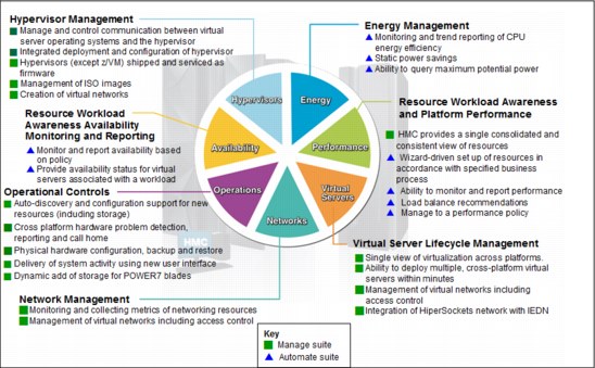
Figure 11-27 Unified Resource Manager functions and suites
Overview
Unified Resource Manager provides the following functions:
•Hypervisor management
Provides tasks for managing the hypervisor lifecycle, managing storage resources, providing RAS and first-failure data capture (FFDC) features, and monitoring the supported hypervisors.
•Ensemble membership management
Provides tasks for creating an ensemble and controlling membership of the ensemble.
•Storage management
Provides a common user interface for allocation and deallocation of physical and virtual storage resources for an ensemble.
•Virtual server management
Provides lifecycle management to create, delete, activate, deactivate, and modify the definitions of virtual servers.
•Virtual network management
Allows management of networking resources for an ensemble.
•Availability management
The resource workload Awareness availability function monitors and reports virtual servers’ availability status, based on the workloads of which they are a part and their associated workload policies.
•Performance management
Provides a global performance view of all the virtual servers that support workloads that are deployed in an ensemble. The virtual server workload performance goal is like a simplified z/OS Workload Manager (WLM) policy:
– You can define, monitor, report, and manage the performance of virtual servers based on workload performance policies.
– Policies are associated to the workload:
• From the overall Workload performance health report, you can review contributions of individual virtual servers.
• You can manage resources across virtual servers within a hypervisor instance.
•Ensemble Availability Management (EAM)
EAM implements basic availability services for the ensemble as part of the Unified Resource Manager. It provides consistent high availability management across virtual servers running on the zEnterprise and zBX in an ensemble, allowing error monitoring and identifying conditions that affect the availability of resources.
The EAM availability assessment is based on user-defined policies for the following objects:
– PR/SM LPARs running on zEnterprise
– Kernel-based virtual machine (KVM) virtual servers running on zBX
– PowerVM virtual servers running on zBX
•EAM enhancements
EAM availability enhancements are based on Workload Resource Group (WRG) definitions. A WRG is a grouping mechanism and management view of the virtual servers that support a business application. The availability definitions are created at the HMC and include these functions:
– Creation of element groups (an element is a virtual server that is associated to a specific workload. Elements are grouped to form a Resource Group. Resource Groups are associated, based on a defined workload, to form a WRG.)
– Addition of virtual servers and element groups to a workload.
– Definition of new availability policies.
– Definition of workload status: Performance and availability compliance.
– Providing workload details summary and reports.
•Energy management:
– Monitors energy usage and controls power-saving settings, which are accessed through the new Monitors Dashboard task.
– Monitoring virtual server resources for processor use and delays, with the capability to create a graphical trend report.
Unified Resource Manager supports different levels of system management. These features determine the management functions and operational controls that are available for a zEnterprise mainframe and any stand-alone zBX:
•Manage suite
Provides the Unified Resource Manager function for core operational controls, installation, and energy monitoring. It is configured by default and activated when an ensemble is created.
•Automate/Advanced Management suite
Advanced Management functions for IBM System x blades delivers a workload definition and performance policy monitoring and reporting. The Automate function adds goal-oriented resource monitoring management and energy management for CPC components, such as System x blades, POWER7 Blades, and the IBM DataPower XI50z. This function is in addition to the Advanced Management function.
Table 11-2 lists the feature codes that must exist to enable Unified Resource Manager. To get ensemble membership, ensure that you also have FC 0025 for the zEC12.
|
Restriction: No new features can be ordered for Unified Resource Manager (URM) with IBM z13.
|
Table 11-2 Unified Resource Manager feature codes and charge indicators
|
Unified Resource Manager managed component
|
Manage1 (per
connection) |
Automatea (per connection)
|
|
Base features
|
FC 00192 - N/C
|
FC 00203 - N/C
|
|
POWER7 blade
|
FC 0178d - Yes
|
FC 0179d - Yes
|
|
DataPower blade
|
FC 0184d - Yes
|
FC 0185d - N/C
|
|
IBM System x blades
|
FC 0182d - Yes
|
FC 0183d - Yes
(also covers the previous Advanced Management function)
|
1 Yes = charged feature, N/C = no charge, N/A = not applicable. All components are either managed through the Manage suite or the Automate/Advanced Management suite. The Automate/Advanced Management suite contains the functions of the Managed suite.
2 FC 0019 is a prerequisite for FC 0020, FC 0184, and FC 0178.
3 FC 0020 is a prerequisite for FC 0185 and FC 0183.
d. All these feature codes are now associated to the zBX Model 004.
APIs for the Unified Resource Manager
The API is a web-oriented programming interface that makes the underlying Unified Resource Manager capabilities available for use by higher-level management applications, system automation functions, and custom scripting. The functions that are available through the API support several important usage scenarios. These scenarios are in virtualization management, resource inventory, provisioning, monitoring, automation, workload-based optimization, and others.
The Web Services API consists of two major components that are accessed by customer applications through Internet Protocol network connections with the HMC.
For more information about the API and the Unified Resource Manager, see z Systems Hardware Management Console Web Services API (Version 2.13.0), SC27-2627, and Building an Ensemble Using IBM zEnterprise Unified Resource Manager, SG24-7921.
|
z/VM V6R3 and Unified Resource Manager: Because of the IBM cloud strategy and adoption of OpenStack, the management of z/VM environments in zManager is now stabilized and will not be further enhanced. zManager will not provide systems management support for z/VM 6.3 and later releases. However, zManager continues to play a distinct and strategic role in the management of virtualized environments that are created by the integrated firmware hypervisors (PR/SM, PowerVM, and x hypervisor, which is based on KVM) of zEnterprise.
|
11.6.2 Ensemble definition and management
The ensemble starts with a pair of HMCs that are designated as the primary and alternate HMCs and are assigned an ensemble identity. The zEnterprise CPCs and zBXs are then added to the ensemble through an explicit action at the primary HMC.
Ensemble Membership Flag
The Ensemble Membership Flag feature, FC 0025, is associated with an HMC when a z13 is ordered.
The new Create Ensemble task allows the Ensemble Administrator user to create an ensemble that contains CPCs and zBXs (Model 004) as members along with images, workloads, virtual networks, and storage pools.
If a z13 is entered into an ensemble, the CPC Details task on the SE and the HMC reflects the ensemble name.
The Unified Resource Manager actions for the ensemble are conducted from a single primary HMC. All other HMCs that are connected to the ensemble can run system management tasks (but not ensemble management tasks) for any CPC or zBX Model 004 within the ensemble. The primary HMC also can be used to run system management tasks on CPCs that are not part of the ensemble. These tasks include Load, Activate, and so on.
The ensemble-specific managed objects include the following objects:
•Ensemble
•Members
•Blades
•BladeCenters
•Hypervisors
•Storage resources
•Virtual servers
•Workloads
When another HMC accesses an ensemble node’s CPC, the HMC can perform the same tasks as though the CPC were not a part of an ensemble. A few of those tasks are extended so that you can configure certain ensemble-specific properties. You can, for example, set the virtual network that is associated with Open Systems Adapters (OSAs) for an LPAR. Showing ensemble-related data in certain tasks is allowed. Generally, if the data affects the operation of the ensemble, the data is read-only on another HMC.
The following tasks show ensemble-related data on another HMC:
•Scheduled operations: Displays ensemble-introduced scheduled operations, but you can only view these scheduled operations.
•User role: Shows ensemble tasks. You can modify and delete those roles.
•Event monitoring: Displays ensemble-related events, but you cannot change or delete the event.
HMC considerations when you use IBM zEnterprise Unified Resource Manager to manage an ensemble
The following considerations are valid when you use Unified Resource Manager to manage an ensemble:
•All HMCs at the supported code level are eligible to create an ensemble. Only HMCs with FC 0094, FC 0092, or FC 0091 at Driver 22 or later can be primary or alternate HMCs for the z13.
•The primary HMC and the alternate HMC must be the same machine type and feature code.
•A single HMC pair manages the ensemble that consists of a primary HMC and an alternate HMC.
•Only one primary HMC manages an ensemble, which can consist of a maximum of eight CPCs and up to eight zBX Model 004 systems.
•The HMC that ran the Create Ensemble wizard becomes the primary HMC. An alternate HMC is elected and paired with the primary.
•The Primary HMC (Version 2.13.0 or later) and Alternate HMC (Version 2.13.0 or later) are displayed on the HMC banner. When the ensemble is deleted, the titles change back to the default.
•A primary HMC is the only HMC that can run ensemble-related management tasks. These tasks include create virtual server, manage virtual networks, and create workload.
•A zEnterprise ensemble can have a maximum of 16 nodes (eight CPCs plus eight zBX Model 004 systems), and is managed by one primary HMC and its alternate. Each node comprises a zEnterprise CPC or a zBX Model 004.
•Any HMC can manage up to 100 CPCs. The primary HMC can run all non-ensemble HMC functions on CPCs that are not members of the ensemble.
•The primary and alternate HMCs must be on the same LAN segment.
•The alternate HMC’s role is to mirror the ensemble configuration and policy information from the primary HMC.
•When failover happens, the alternate HMC becomes the primary HMC. This behavior is the same as primary and alternate SEs.
11.6.3 HMC availability
The HMC is attached to the same LAN as the server’s and zBX Model 004 SEs. This LAN is referred to as the Customer Managed Management Network. The HMC communicates with each CPC and with each zBX Model 004 SE.
If the z13 node is defined as a member of an ensemble, the primary HMC is the authoritative controlling (stateful) component for the Unified Resource Manager configuration. It also is the stateful component for policies that have a scope that spans all of the managed CPCs and SEs in the ensemble. The managing HMC has an active role in ongoing system monitoring and adjustment.
This configuration requires the HMC to be configured in a primary/alternate configuration. It also cannot be disconnected from the managed ensemble members.
|
Failover: The primary HMC and its alternate must be connected to the same LAN segment. This configuration allows the alternate HMC to take over the IP address of the primary HMC during failover processing.
|
11.6.4 Considerations for multiple HMCs
Customers often deploy multiple HMC instances to manage an overlapping collection of systems. Until the emergence of ensembles, all of the HMCs were peer consoles to the managed systems. Using this configuration, all management actions are possible to any of the reachable systems while logged in to a session on any of the HMCs (subject to access control). With the Unified Resource Manager, this paradigm has changed. One ensemble is managed by one primary and alternate HMC pair. Multiple ensembles require an equal number of multiple primary and alternate HMC pairs to manage them. If a z13, a zEnterprise System, or a zBX Model 004 is added to an ensemble, management actions that target that object can be done only from the managing (primary) HMC for that ensemble.
11.6.5 HMC browser session to a primary HMC
A remote HMC browser session to the primary HMC that manages an ensemble allows a user who is logged on to another HMC or a workstation to perform ensemble-related actions.
11.6.6 HMC ensemble topology
The system management functions that pertain to an ensemble use the HMC and the z13, zEnterprise System, or zBX Model 004 SEs through the internode management network (INMN) to provide the required connectivity.
Figure 11-28 depicts an ensemble with a zEC12, a z13, and a stand-alone zBX that are managed by the Unified Resource Manager in the primary and alternate HMCs.

Figure 11-28 Ensemble example with primary and alternate HMCs
For the stand-alone CPC ensemble node (zEC12), an OSA-Express4S (CHPID type OSD) connects to the zBX IEDN switch. The HMCs also communicate with all the components of the ensemble by the SCH in the z13, the BPH in the zEC12, and the INMN switch in the zBX Model 004.
The OSA-Express5S (or OSA Express 4S) 10 GbE ports (CHPID type OSX) in the z13 are plugged with customer-provided 10 GbE cables to the IEDN zBX switch. These cables are either short reach (SR) or long reach (LR), depending on the OSA feature.
1 For a customer-supplied switch, multicast must be enabled at the switch level.
..................Content has been hidden....................
You can't read the all page of ebook, please click here login for view all page.