

Disaster recovery
IBM Virtualization Engine TS7700 failover scenarios, and disaster recovery (DR) planning and considerations, with or without Geographically Dispersed Parallel Sysplex (GDPS), are covered. The new feature Flash Copy for DR testing is highlighted.
The following topics are covered:
•Copy Export Implementation and Usage
•GDPS Implementation and Considerations
•Flash Copy for disaster recovery testing
10.1 TS7700 Virtualization Engine grid failover principles
To better understand and plan for the actions to be performed with the TS7700 Virtualization Engine grid configuration in failures, key concepts for grid operation and the many failure scenarios that the grid has been designed to handle are described. A TS7700 Virtualization Engine grid configuration provides the following data access and availability characteristics:
•Accessing the data on a particular cluster requires that a host mount request be sent on a virtual device address that is defined for that cluster. The virtual device addresses for each cluster are independent. In a prior generation, the Peer-to-Peer (PTP) Virtual Tape Server (VTS) mount request was sent on a virtual device address defined for a virtual tape controller and the virtual tape controller, then decided which VTS to use for data access.
•All logical volumes are accessible through any of the virtual device addresses on the TS7700 Virtualization Engine clusters in the grid configuration. The preference is to access a copy of the volume in the Tape Volume Cache (TVC) that is associated with the TS7700 Virtualization Engine cluster on which the mount request is received. If a recall is required to place the logical volume in the TVC on that TS7700 Virtualization Engine cluster, it is done as part of the mount operation.
If a copy of the logical volume is not available at that TS7700 Virtualization Engine cluster (either because it does not have a copy or the copy it does have is inaccessible because of an error), and a copy is available at another TS7700 Virtualization Engine cluster in the grid, the volume is accessed through the TVC at the TS7700 Virtualization Engine cluster that has the available copy. If a recall is required to place the logical volume in the TVC on the other TS7700 Virtualization Engine cluster, it is done as part of the mount operation.
•Whether a copy is available at another TS7700 Virtualization Engine cluster in a multicluster grid depends on the Copy Consistency Point assigned to the logical volume when it was written. The Copy Consistency Point is set through the Management Class storage construct. It specifies if and when a copy of the data is made between the TS7700 Virtualization Engine clusters in the grid configuration. The following Copy Consistency Policies can be assigned:
– Rewind Unload (RUN) Copy Consistency Point: If a data consistency point of RUN is specified, the data created on one TS7700 Virtualization Engine cluster is copied to the other TS7700 Virtualization Engine cluster as part of successful rewind unload command processing, meaning that for completed jobs, a copy of the volume exists on both TS7700 Virtualization Engine clusters. Access to data written by completed jobs (successful Rewind Unload) before the failure is maintained through the other TS7700 Virtualization Engine cluster. Access to data of incomplete jobs that were in process at the time of the failure is not provided.
– Deferred Copy Consistency Point: If a data consistency point of Deferred is specified, the data created on one TS7700 Virtualization Engine cluster is copied to the specified TS7700 Virtualization Engine clusters after successful rewind unload command processing. Access to the data through the other TS7700 Virtualization Engine cluster depends on when the copy completes. Because there is a delay in creating the copy, access might or might not be available when a failure occurs.
– No Copy Consistency Point: If a data consistency point of No Copy is specified, the data created on one TS7700 Virtualization Engine cluster is not copied to the other TS7700 Virtualization Engine cluster. If the TS7700 Virtualization Engine cluster to which data was written fails, the data for that logical volume is inaccessible until that TS7700 Virtualization Engine cluster’s operation is restored.
– Synchronous Copy Consistency Point: When Synchronous Mode is specified, the data that is written to TS7700 is compressed and simultaneously written or duplexed to two TS7700 locations. When Sync is used, two clusters must be defined as sync points. All other clusters can be any of the remaining consistency point options allowing extra copies to be made.
– Copy Consistency Override: With the introduction of the multicluster grid, the logical volume Copy Consistency Override feature has been enabled. By using Cluster Settings → Copy Policy Override, on each library, you can control existing RUN consistency points. Be careful in using this option because it might mean that there are fewer copies of the data available than your copy policies have specified.
•The Volume Removal policy for hybrid grid configurations is available in any grid configuration that contains at least one TS7720 cluster. Because the TS7720 “Disk-Only” solution has a maximum storage capacity that is the size of its TVC, after the cache fills, this policy allows logical volumes to be automatically removed from cache while a copy is retained within one or more peer clusters in the grid. When the auto-removal starts, all volumes in the scratch (Fast Ready) category are removed first because these volumes are intended to hold temporary data. This mechanism can remove old volumes in a private category from the cache to meet a predefined cache usage threshold if a copy of the volume is retained on one of the remaining clusters. A TS7740 cluster failure can affect the availability of old volumes (no logical volumes are removed from a TS7740 cluster).
•If a logical volume is written on one of the TS7700 Virtualization Engine clusters in the grid configuration and copied to the other TS7700 Virtualization Engine cluster, the copy can be accessed through the other TS7700 Virtualization Engine cluster. This is subject to the so-called volume ownership.
At any time, a logical volume is “owned” by a cluster. The owning cluster has control over access to the volume and changes to the attributes associated with the volume (such as category or storage constructs). The cluster that has ownership of a logical volume can surrender it dynamically to another cluster in the grid configuration that is requesting a mount of the volume.
When a mount request is received on a virtual device address, the TS7700 Virtualization Engine cluster for that virtual device must have ownership of the volume to be mounted or must obtain the ownership from the cluster that currently owns it. If the TS7700 Virtualization Engine clusters in a grid configuration and the communication paths between them are operational (grid network), the change of ownership and the processing of logical volume-related commands are transparent to the operation of the TS7700 Virtualization Engine cluster.
However, if a TS7700 Virtualization Engine cluster that owns a volume is unable to respond to requests from other clusters, the operation against that volume fails, unless more direction is given. Clusters will not automatically assume or take over ownership of a logical volume without being directed. This is done to prevent the failure of the grid network communication paths between the TS7700 Virtualization Engine clusters resulting in both clusters thinking that they have ownership of the volume. If more than one cluster has ownership of a volume, that might result in the volume’s data or attributes being changed differently on each cluster, resulting in a data integrity issue with the volume.
If a TS7700 Virtualization Engine cluster fails or is known to be unavailable (for example, a power fault in the IT center) or needs to be serviced, its ownership of logical volumes is transferred to the other TS7700 Virtualization Engine cluster through one of the following modes.
These modes are set through the management interface (MI):
– Read Ownership Takeover: When Read Ownership Takeover (ROT) is enabled for a failed cluster, ownership of a volume is allowed to be taken from a TS7700 Virtualization Engine cluster that has failed. Only read access to the volume is allowed through the other TS7700 Virtualization Engine cluster in the grid. After ownership for a volume has been taken in this mode, any operation attempting to modify data on that volume or change its attributes is failed. The mode for the failed cluster remains in place until a different mode is selected or the failed cluster is restored.
– Write Ownership Takeover: When Write Ownership Takeover (WOT) is enabled for a failed cluster, ownership of a volume is allowed to be taken from a cluster that has been marked as failed. Full access is allowed through the other TS7700 Virtualization Engine cluster in the grid. The mode for the failed cluster remains in place until a different mode is selected or the failed cluster is restored.
– Service prep/service mode: When a TS7700 Virtualization Engine cluster is placed in service preparation mode or is in service mode, ownership of its volumes is allowed to be taken by the other TS7700 Virtualization Engine cluster. Full access is allowed. The mode for the cluster in service remains in place until it is taken out of service mode.
•In addition to the manual setting of one of the ownership takeover modes, an optional automatic method named Autonomic Ownership Takeover Manager (AOTM) is available when each of the TS7700 Virtualization Engine clusters is attached to a TS3000 System Console (TSSC) and there is a communication path provided between the TSSCs. AOTM is enabled and defined by the IBM service support representative (SSR). If the clusters are in close proximity of each other, multiple clusters in the same grid can be attached to the same TSSC and the communication path is not required.
|
Guidance: The links between the TSSCs must not be the same physical links that are also used by cluster grid gigabit links. AOTM must have a different network to be able to detect that a missing cluster is actually down, and that the problem is not caused by a failure in the grid gigabit wide area network (WAN) links.
|
If enabled by the IBM SSR, if a TS7700 Virtualization Engine cluster cannot obtain ownership from the other TS7700 Virtualization Engine cluster because it does not get a response to an ownership request, a check is made through the TSSCs to determine whether the owning TS7700 Virtualization Engine cluster is inoperable or that the communication paths to it are not functioning. If the TSSCs determine that the owning TS7700 Virtualization Engine cluster is inoperable, they enable either read or write ownership takeover, depending on what was set by the IBM SSR.
•AOTM enables an ownership takeover mode after a grace period, and can be configured only by an IBM SSR. Therefore, jobs can intermediately fail with an option to try again until the AOTM enables the configured takeover mode. The grace period is set to 20 minutes, by default. The grace period starts when a TS7700 detects that a remote TS7700 has failed. It can take several minutes.
The following OAM messages can be displayed up until the point when AOTM enables the configured ownership takeover mode:
– CBR3758E Library Operations Degraded
– CBR3785E Copy operations disabled in library
– CBR3786E VTS operations degraded in library
– CBR3750I Message from library libname: G0013 Library libname has experienced an unexpected outage with its peer library libname. Library libname might be unavailable or a communication issue might be present.
– CBR3750I Message from library libname: G0009 Autonomic ownership takeover manager within library libname has determined that library libname is unavailable. The Read/Write ownership takeover mode has been enabled.
– CBR3750I Message from library libname: G0010 Autonomic ownership takeover manager within library libname determined that library libname is unavailable. The Read-Only ownership takeover mode has been enabled.
•A failure of a TS7700 Virtualization Engine cluster causes the jobs using its virtual device addresses to abend. To rerun the jobs, host connectivity to the virtual device addresses in the other TS7700 Virtualization Engine cluster must be enabled (if not already) and an appropriate ownership takeover mode selected. If the other TS7700 Virtualization Engine cluster has a valid copy of a logical volume, the jobs can be tried again.
If a logical volume is being accessed in a remote cache through the Ethernet link and that link fails, the job accessing that volume also fails. If the failed job is attempted again, the TS7700 Virtualization Engine uses another Ethernet link. You can have four 1-Gbps Ethernet links or two 10-Gbps Ethernet links. If all links fail, access to any data in a remote cache is not possible.
10.2 Failover scenarios
As part of a total systems design, you must develop business continuity procedures to instruct IT personnel in the actions that they need to take in a failure. Test those procedures either during the initial installation of the system or at another time.
The scenarios that are described are from the IBM Virtualization Engine TS7700 Series Grid Failover Scenarios white paper, which was written to assist IBM specialists and clients in developing such testing plans. The white paper is available at the following address:
The white paper documents a series of TS7700 Virtualization Engine Grid failover test scenarios for z/OS that were run in an IBM laboratory environment. Single failures of all major components and communication links and some multiple failures are simulated.
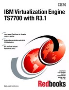
10.2.1 Test configuration
The hardware configuration used for the laboratory test scenarios is shown in Figure 10-1.
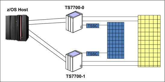
Figure 10-1 Grid test configuration for a two-cluster grid
For the Automatic Takeover scenarios, a TSSC attached to each of the TS7700 Virtualization Engine clusters is required and an Ethernet connection between the TSSCs is required. Although all the components tested were local, the results of the tests are similar, if not the same, for remote configurations. All Fibre Channel connections (FICON) were direct, but again, the results are valid for configurations that use FICON directors. Any supported level of z/OS software, and current levels of TS7700 Virtualization Engine and TS3500 Tape Library microcode, will all provide similar results. The test environment was MVS/JES2. Failover capabilities are the same for all supported host platforms, although host messages differ and host recovery capabilities might not be supported in all environments.
For the tests, all host jobs are routed to the virtual device addresses associated with TS7700 Virtualization Engine Cluster 0. The host connections to the virtual device addresses in TS7700 Virtualization Engine Cluster 1 are used in testing recovery for a failure of TS7700 Virtualization Engine Cluster 0.
An IBM Support team must be involved in the planning and execution of any failover tests. In certain scenarios, intervention by an IBM SSR might be needed to initiate failures or restore “failed” components to operational status.
Test job mix
The test jobs running during each of the failover scenarios consist of 10 jobs that mount single specific logical volumes for input (read), and five jobs that mount single scratch logical volumes for output (write). The mix of work used in the tests is purely arbitrary, and any mix is suitable. However, in order for recovery to be successful, logical drives must be available for a swap. For that reason, fewer than the maximum number of virtual drives must be active during testing. Also, many messages are generated during some scenarios, and fewer jobs reduce the number of host console messages.
|
Clarification: The following scenarios were tested using TS7740 Virtualization Engine clusters with attached TS3500 Tape Libraries. The scenarios also apply to the TS7720 Virtualization Engines if they are limited to virtual volume management and grid communication.
|
10.2.2 Failover scenario 1
The scenario shown in Figure 10-2 assumes that one host link to TS7700-0 fails. The failure might be the intermediate FICON directors, FICON channel extenders, or remote channel extenders.

Figure 10-2 Failure of a host link to a TS7700 Virtualization Engine
Effects of the failure
You see the following effects of the failure:
•All grid components continue to operate.
•All channel activity on the failing host link is stopped.
•Host channel errors are reported or error information becomes available from the intermediate equipment.
•If alternate paths exist from the host to either TS7700, the host I/O operations can continue. Ownership takeover modes are not needed.
•All data remains available.
Recovery from failure
Use the following information to help you recover from the failures:
•Normal error recovery procedures apply for the host channel and the intermediate equipment.
•You must contact your IBM SSR to repair the failed connection.
10.2.3 Failover scenario 2
The scenario shown in Figure 10-3 assumes a failure of both links between the TS7700 Virtualization Engine clusters.
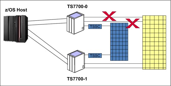
Figure 10-3 Failure of both links between the TS7700 Virtualization Engine clusters
Effects of the failure
You will see the following effects of the failure:
•Jobs on virtual device addresses on TS7700 Cluster 0 continue to run because the logical volumes are using the TVC in Cluster 0.
•All scratch mounts to TS7700 Cluster 0 will succeed if it owns one or more volumes in the scratch category at the time of the mount operation. After the scratch volumes owned by TS7700 Cluster 0 are exhausted, scratch mounts will begin to fail.
•The grid enters the Grid Links Degraded state and the VTS Operations Degraded state.
•All copy operations are stopped.
•The grid enters the Copy Operation Disabled state.
•If the RUN Copy Consistency Point is being used, the grid also enters the Immediate Mode Copy Completion’s Deferred state.
•Call Home support is started.
Recovery from failure
Contact your IBM SSR for repair of the failed connection.
10.2.4 Failover scenario 3
The scenario shown in Figure 10-4 assumes a failure of a link between TS7700 Virtualization Engine clusters with remote mounts.

Figure 10-4 Failure of a link between TS7700 Virtualization Engine clusters with remote mounts
Effects of the failure
You will see the following effects of the failure:
•Any job in progress that is using the remote link between TS7700 Cluster 0 and TS7700 Cluster 1 that was disconnected will fail.
•If the job is resubmitted, it will succeed by using the other link.
•The grid enters the Grid Links Degraded state and the VTS Operations Degraded state.
•Call Home support is started.
Recovery from failure
Contact your IBM SSR to repair the failed connections.
10.2.5 Failover scenario 4
The scenario shown in Figure 10-5 assumes a failure of both links between TS7700 Virtualization Engine clusters with remote mounts.
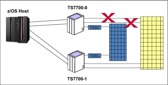
Figure 10-5 Failure of both links between TS7700 Virtualization Engine clusters with remote mounts
Effects of the failure
You will see the following effects of the failure:
•Jobs on virtual device addresses on TS7700 Cluster 0 that are using TS7700 Cluster 1 as the TVC cluster will fail.
•Subsequent specific mount jobs that attempt to access the data through TS7700 Cluster 0 that exist only on TS7700 Cluster 1 will fail.
•All scratch mounts to TS7700 Cluster 0 will succeed if Cluster 0 owns one or more volumes in the scratch category at the time of the mount operation. After the scratch volumes owned by TS7700 Cluster 0 are exhausted, scratch mounts will begin to fail.
•All copy operations are stopped.
•The grid enters the Grid Links Degraded state, the VTS Operations Degraded state, and the grid enters the Copy Operation Disabled state.
•Call Home support is started.
|
Tip: Although the data is on TS7700-1, if it was mounted on TS7700-0 when the failure occurred, it is not accessible through the virtual device addresses on TS7700-1 because ownership transfer cannot occur.
|
Recovery from failure
To recover from the failures, you must contact your IBM SSR to repair the failed connections.
10.2.6 Failover scenario 5
The scenario shown in Figure 10-6 assumes a failure of the local TS7700 Virtualization Engine Cluster 0.

Figure 10-6 Failure of the local TS7700 Virtualization Engine Cluster 0
Effects of the failure
You will see the following effects of the failure:
•Virtual tape device addresses for TS7700 Cluster 0 will become unavailable.
•All channel activities on the failing host links are stopped.
•Host channel errors are reported or error information becomes available from the intermediate equipment.
•Jobs that were using the virtual device addresses of TS7700 Cluster 0 will fail.
•Scratch mounts that target volumes that are owned by the failed cluster will also fail until write ownership takeover mode is enabled. Scratch mounts that target pre-owned volumes will succeed. The grid enters the Copy Operation Disabled and VTS Operations Degraded states.
•If the RUN Copy Consistency Point is being used, the grid also enters the Immediate Mode Copy Completion’s Deferred state.
•All copied data can be made accessible through TS7700 Cluster 1 through one of the takeover modes. If a takeover mode for TS7700 Cluster 0 is not enabled, data will not be accessible through TS7700 Cluster 1 even if it has a valid copy of the data if the volume is owned by TS7700 Cluster 0.
Recovery from failure
To recover from the failures, complete the following steps:
1. Enable write or read-only ownership takeover through the MI.
2. Rerun the failed jobs using the virtual device addresses associated with TS7700 Virtualization Engine Cluster 1.
3. Normal error recovery procedures and repair apply for the host channels and the intermediate equipment.
4. Contact your IBM SSR to repair the failed TS7700 cluster.
10.2.7 Failover scenario 6
The scenario shown in Figure 10-7 considers a failure of both links between TS7700 Virtualization Engine clusters with Automatic Takeover.

Figure 10-7 Failure of both links between TS7700 Virtualization Engine clusters with Automatic Takeover
Effects of the failure
You will see the following effects of the failure:
•Specific mount jobs subsequent to the failure using virtual device addresses on Cluster 0 that need to access volumes that are owned by Cluster 1 will fail (even if the data is local to Cluster 0). Jobs using virtual device addresses on Cluster 1 that need to access volumes that are owned by Cluster 0 will also fail.
•All scratch mounts to Cluster 0 succeed if it owns one or more volumes in the scratch category at the time of the mount operation. After the scratch volumes owned by Cluster 0 are exhausted, scratch mounts will begin to fail.
•All copy operations are stopped.
•The grid enters the Grid Links Degraded state, the VTS Operations Degraded state, and the Copy Operation Disabled state.
•If the RUN Copy Consistency Point is being used, the grid also enters the Immediate Mode Copy Completion’s Deferred state.
•Call Home support is started.
Recovery from failure
Contact your IBM SSR for repair of the failed connections.
10.2.8 Failover scenario 7
The scenario shown in Figure 10-8 assumes a production site with two TS7700 clusters (Cluster 0 and Cluster 1) active in production. The third TS7700 cluster (Cluster 2) is at a remote location without attachment to the production hosts. Cluster 2 is attached to a backup host. Its devices are varied offline, and there is no active host.
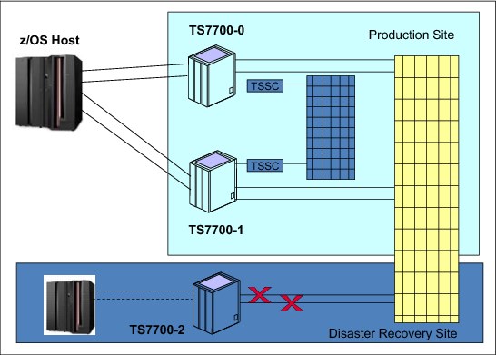
Figure 10-8 Three-cluster grid with failure on two links to Cluster 2
Failures related to Cluster 0 and Cluster 1 are already described in the previous scenarios. This scenario considers what to do when both links to Cluster 2 fail and the only shared component from Cluster 0 and Cluster 1 to Cluster 2 is the network.
Effects of the failure
You will see the following effects of the failure:
•All copy operations between Cluster 2 and rest of the clusters are stopped.
•All copy operations between Cluster 0 and Cluster 1 continue.
•The grid enters the Grid Links Degraded state, the VTS Operations Degraded state, and the Copy Operations Disabled state.
•If the RUN Copy Consistency Point is being used for Cluster 2, the grid also enters the Immediate Mode Copy Completion’s Deferred state.
•Call Home support is started.
Recovery from failure
Contact your IBM SSR for repair of the failed connections.
10.2.9 Failover scenario 8
This scenario assumes a four-cluster hybrid grid configuration with a partitioned workload. At the production site, two TS7720 clusters are installed. At the remote site, two TS7740 clusters, which are attached to TS3500 tape libraries, are installed.
Virtual volumes are written on one cluster at the local site and copied to one cluster at the remote site, so that a copy of a volume exists both in Cluster 0 and Cluster 2, and in Cluster 1 and Cluster 3.
In the scenario, shown in Figure 10-9, the remote site fails. The grid WAN is operational.

Figure 10-9 Four-cluster hybrid grid multiple failures
Effect of the failures
You will see the following effects of the failures:
•Jobs on virtual device addresses on Cluster 0 continue to run because the logical volumes are in the TVC on Cluster 0 or Cluster 1.
Jobs that access old volumes, which the automatic removal mechanisms have already removed from the production clusters, will fail. Because TS7720s cannot copy to TS7740, they might eventually become full, and all scratch mounts and specific mounts with modifications will fail.
•The grid enters the Copy Operation Disabled and VTS Operations Degraded states.
•If the RUN Copy Consistency Point is being used, the grid also enters the Immediate Mode Copy Completion’s Deferred state.
•All copy operations for Cluster 2 and Cluster 3 are stopped.
•Call Home support is started.
Recovery from failure
Normal error recovery procedures and repair apply for the host channels and the intermediate equipment. To recover from the failures, you must contact your IBM SSR to repair the failed connections.
10.3 Planning for disaster recovery
Although you can hope that a disaster does not happen, planning for such an event is important. Information is provided that can be used in developing a disaster recovery plan as it relates to a TS7700 Virtualization Engine.
Many aspects of disaster recovery planning must be considered:
•How critical is the data in the TS7700 Virtualization Engine?
•Can the loss of some of the data be tolerated?
•How much time can be tolerated before resuming operations after a disaster?
•What are the procedures for recovery and who will run them?
•How will you test your procedures?
10.3.1 Grid configuration
With the TS7700 Virtualization Engine, two types of configurations can be installed:
•Stand-alone cluster
•Multicluster grid
With a stand-alone system, a single TS7700 Virtualization Engine cluster is installed. If the site at which that system is installed is destroyed, the data that is associated with the TS7700 Virtualization Engine might also have been lost. If a TS7700 Virtualization Engine is not usable because of an interruption of utility or communication services to the site, or significant physical damage to the site or the TS7700 Virtualization Engine itself, access to the data that is managed by the TS7700 Virtualization Engine is restored through automated processes designed into the product.
The recovery process assumes that the only elements available for recovery are the stacked volumes. It further assumes that only a subset of the volumes is undamaged after the event. If the physical cartridges have been destroyed or irreparably damaged, recovery is not possible, as with any other cartridge types. It is important that you integrate the TS7700 Virtualization Engine recovery procedure into your current disaster recovery procedures.
|
Remember: The disaster recovery process is a joint exercise that requires your involvement and your IBM SSR to make it as comprehensive as possible.
|
For many clients, the potential data loss or the recovery time required with a stand-alone TS7700 Virtualization Engine is not acceptable. For those clients, the TS7700 Virtualization Engine grid provides a near-zero data loss and expedited recovery-time solution. With a TS7700 Virtualization Engine multicluster grid configuration, two, three, or four TS7700 Virtualization Engine clusters are installed, typically at two or three sites, and interconnected so that data is replicated among them. The way that the two or three sites are used then differs, depending on your requirements.
In a two-cluster grid, the typical use is that one of the sites is the local production center and the other site is a backup or disaster recovery center, separated by a distance dictated by your company’s requirements for disaster recovery.
In a three-cluster grid, the typical use is that two sites are connected to a host and the workload is spread evenly between them. The third site is strictly for disaster recovery and there probably are no connections from the production host to the third site. Another use for a three-cluster grid might consist of three production sites, which are all interconnected and holding the backups of each other.
In a four-cluster grid, disaster recovery and high availability can be achieved, ensuring that two local clusters keep RUN or SYNC volume copies and that both clusters are attached to the host. The third and fourth remote clusters hold deferred volume copies for disaster recovery. This design can be configured in a crossed way, which means that you can run two production data centers, with each production data center serving as a backup for the other.
The only connection between the production sites and the disaster recovery site is the grid interconnection. There is normally no host connectivity between the production hosts and the disaster recovery site’s TS7700 Virtualization Engine. When client data is created at the production sites, it is replicated to the disaster recovery site as defined through Outboard policy management definitions and storage management subsystem (SMS) settings.
10.3.2 Planning guidelines
As part of planning a TS7700 Virtualization Engine grid configuration to address this solution, you need to consider the following items:
•Plan for the necessary WAN infrastructure and bandwidth to meet the copy requirements that you need. You generally need more bandwidth if you are primarily using a Copy Consistency Point of RUN because any delays in copy time caused by bandwidth limitations result in longer job run times. If you have limited bandwidth available between sites, use the Deferred Copy Consistency Point or only copy the data that is critical to the recovery of your key operations. The amount of data sent through the WAN can possibly justify the establishment of a separate, redundant, and dedicated network only for the multicluster grid.
•If you use a consistency point of deferred copy, and the bandwidth is the limiting factor, some data might not be replicated between the sites, and the jobs that created that data must be rerun. This is also a factor to consider in the implementation of Copy Export for disaster recovery because the export does not capture any volumes in the export pool that are not currently in the TVC of the export cluster.
•Plan for host connectivity at your disaster recovery site with sufficient resources to run your critical workloads. If the local TS7700 Virtualization Engine cluster becomes unavailable, there is no local host access to the data in the disaster recovery site’s TS7700 Virtualization Engine cluster through the local cluster.
•Design and code the Data Facility System Management Subsystem (DFSMS) automatic class selection (ACS) routines to control the data that gets copied and by which Copy Consistency Point. You might need to consider management policies for testing your procedures at the disaster recovery site that are different from the production policies.
•Prepare procedures that your operators execute if the local site becomes unusable. The procedures include tasks such as bringing up the disaster recovery host, varying the virtual drives online, and placing the disaster recovery TS7700 Virtualization Engine cluster in one of the ownership takeover modes.
•Perform a periodic capacity planning of your tape setup to evaluate whether the disaster setup is still capable of handling the production in a disaster.
•If encryption is used in production, ensure that the disaster site supports encryption, also. The Key Encrypting Keys (KEKs) for production must be available at the disaster recovery site to enable the data key to be decrypted. Default keys are supported and enable key management without modifications required on the TS7740. On the tape setup, the TS1120/TS1130/TS1140, the TS7700 Virtualization Engine, and the MI itself must support encryption. Validate that the TS7700 Virtualization Engine can communicate with the Encryption Key Manager (EKM), IBM Security Key Lifecycle Manager (formerly Tivoli Key Lifecycle Manager), or IBM Security Key Lifecycle Manager for z/OS, and that the keystore itself is available.
•Consider how you will test your disaster recovery procedures. Many scenarios can be set up:
– Will it be based on all data from an existing TS7700 Virtualization Engine?
– Will it be based on using the Copy Export function and an empty TS7700 Virtualization Engine?
– Will it be based on stopping production of one TS7700 Virtualization Engine and running production to the other during a period when one cluster is down for service?
10.4 High availability and disaster recovery configurations
A few examples of grid configurations are addressed. Remember that these examples are a small subset of possible configurations and are only provided to show how the grid technology can be used. With five-cluster or six-cluster grids, there are many more ways to configure a grid.
Two-cluster grid
With a two-cluster grid, you can configure the grid for disaster recovery, high availability, or both. Configuration considerations for two-cluster grids are described. The scenarios presented are typical configurations. Other configurations are possible and might be better suited for your environment.
Disaster recovery configuration
Information that is needed to plan for a TS7700 Virtualization Engine two-cluster grid configuration to be used specifically for disaster recovery purposes is provided.
A natural or human-caused event has made the local site’s TS7700 Virtualization Engine cluster unavailable. The two TS7700 Virtualization Engine clusters are in separate locations, which are separated by a distance dictated by your company’s requirements for disaster recovery. The only connection between the local site and the disaster recovery site are the grid interconnections. There is no host connectivity between the local hosts and the disaster recovery site’s TS7700 Virtualization Engine.
Figure 10-10 summarizes this configuration.

Figure 10-10 Disaster recovery configuration
Consider the following information as part of planning a TS7700 Virtualization Engine grid configuration to implement this solution:
•Plan for the necessary WAN infrastructure and bandwidth to meet the copy requirements that you need. You generally need more bandwidth if you are primarily using a Copy Consistency Point of RUN because any delays in copy time caused by bandwidth limitations can result in an elongation of job run times. If you have limited bandwidth available between sites, have data that are critical copied with a consistency point of RUN, with the rest of the data using the Deferred Copy Consistency Point.
•Plan for host connectivity at your disaster recovery site with sufficient resources to perform your critical workloads.
•Design and code the DFSMS ACS routines to control the data that gets copied and by which Copy Consistency Point.
•Prepare procedures that your operators complete if the local site becomes unusable. The procedures include tasks, such as bringing up the disaster recovery host, varying the virtual drives online, and placing the disaster recovery TS7700 Virtualization Engine cluster in one of the ownership takeover modes unless AOTM is configured.
Configuring for high availability
The information needed to plan for a TS7700 Virtualization Engine two-cluster grid configuration to be used specifically for high availability is provided. The assumption is that continued access to data is critical, and no single point of failure, repair, or upgrade can affect the availability of data.
In a high-availability configuration, both TS7700 Virtualization Engine clusters are located within metro distance of each other. These clusters are connected through a LAN. If one of them becomes unavailable because it has failed, or is undergoing service or being updated, data can be accessed through the other TS7700 Virtualization Engine cluster until the unavailable cluster is made available.
As part of planning a TS7700 Virtualization Engine grid configuration to implement this solution, consider the following information:
•Plan for the virtual device addresses in both clusters to be configured to the local hosts. In this way, a total of 512 virtual tape devices are available for use (256 from each TS7700 Virtualization Engine cluster).
•Set up a Copy Consistency Point of RUN for both clusters for all data to be made highly available. With this Copy Consistency Point, as each logical volume is closed, it is copied to the other TS7700 Virtualization Engine cluster.
•Design and code the DFSMS ACS routines to set the necessary Copy Consistency Point.
•Ensure that AOTM is configured for an automated logical volume ownership takeover method in case a cluster becomes unexpectedly unavailable within the grid configuration. Alternatively, prepare written instructions for the operators that describe how to perform the ownership takeover manually, if necessary. See “Autonomic Ownership Takeover Manager” on page 78 for more details about AOTM.
Figure 10-11 summarizes this configuration.
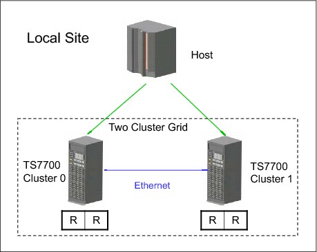
Figure 10-11 Availability configuration
Configuring for disaster recovery and high availability
You can configure a TS7700 Virtualization Engine two-cluster grid configuration to provide both disaster recovery and high availability solutions.
The assumption is that the two TS7700 Virtualization Engine clusters are in separate locations, separated by a distance dictated by your company’s requirements for disaster recovery. In addition to the configuration considerations for disaster recovery, you need to plan for the following items:
•Access to the FICON channels on the TS7700 Virtualization Engine cluster at the disaster recovery site from your local site’s hosts. This can involve connections using dense wavelength division multiplexing (DWDM) or channel extender, depending on the distance separating the two sites. If the local TS7700 Virtualization Engine cluster becomes unavailable, you use this remote access to continue your operations using the remote TS7700 Virtualization Engine cluster.
•Because the virtual devices on the remote TS7700 Virtualization Engine cluster are connected to the host through a DWDM or channel extension, there can be a difference in read or write performance when compared to the virtual devices on the local TS7700 Virtualization Engine cluster. If performance differences are a concern, consider only using the virtual device addresses in the remote TS7700 Virtualization Engine cluster when the local TS7700 Virtualization Engine is unavailable. If that is important, you need to provide operator procedures to vary online and offline the virtual devices to the remote TS7700 Virtualization Engine.
•You might want to have separate Copy Consistency Policies for your disaster recovery data versus your data that requires high availability.
Figure 10-12 summarizes this configuration.
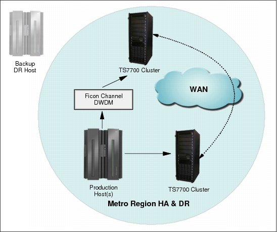
Figure 10-12 Availability and disaster recovery configuration
Three-cluster grid
With a three-cluster grid, you can configure the grid for disaster recovery and high availability or use dual production sites that share a common disaster recovery site. Configuration considerations for three-cluster grids are described. The scenarios presented are typical configurations. Other configurations are possible and might be better suited for your environment.
The planning considerations for a two-cluster grid also apply to a three-cluster grid.
High availability and disaster recovery
Figure 10-13 illustrates a combined high availability and disaster recovery solution for a three-cluster grid. In this example, Cluster 0 and Cluster 1 are the high-availability clusters and are local to each other (less than 50 kilometers (31 miles) apart). Cluster 2 is at a remote site that is away from the production site or sites. The virtual devices in Cluster 0 and Cluster 1 are online to the host and the virtual devices in Cluster 2 are offline to the host. The host accesses the 512 virtual devices provided by Cluster 0 and Cluster 1. Host data that are written to Cluster 0 is copied to Cluster 1 at Rewind Unload time. Host data written to Cluster 1 is written to Cluster 0 at Rewind Unload time. Host data written to Cluster 0 or Cluster 1 is copied to Cluster 2 on a Deferred basis.
The Copy Consistency Points at the disaster recovery site (NNR) are set to create a copy only of host data at Cluster 2. Copies of data are not made to Cluster 0 and Cluster 1. This allows for disaster recovery testing at Cluster 2 without replicating to the production site clusters.
Figure 10-13 shows an optional host connection that can be established to remote Cluster 2 using DWDM or channel extenders. With this configuration, you need to define an extra 256 virtual devices at the host for a total of 768 devices.
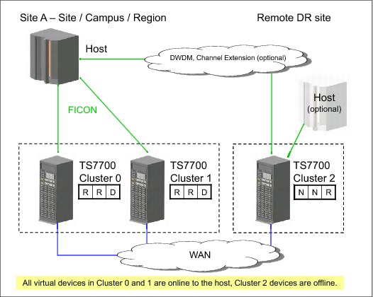
Figure 10-13 High availability and disaster recovery configuration
Dual production site and disaster recovery
Figure 10-14 on page 706 illustrates dual production sites that are sharing a disaster recovery site in a three-cluster grid (similar to a hub-and-spoke model). In this example, Cluster 0 and Cluster 1 are separate production systems that can be local to each other or distant from each other. The disaster recovery cluster, Cluster 2, is at a remote site at a distance away from the production sites. The virtual devices in Cluster 0 are online to Host A and the virtual devices in Cluster 1 are online to Host B. The virtual devices in Cluster 2 are offline to both hosts. Host A and Host B access their own set of 256 virtual devices provided by their respective clusters. Host data written to Cluster 0 is not copied to Cluster 1. Host data written to Cluster 1 is not written to Cluster 0. Host data written to Cluster 0 or Cluster 1 is copied to Cluster 2 on a Deferred basis.
The Copy Consistency Points at the disaster recovery site (NNR) are set to create only a copy of host data at Cluster 2. Copies of data are not made to Cluster 0 and Cluster 1. This allows for disaster recovery testing at Cluster 2 without replicating to the production site clusters.
Figure 10-14 shows an optional host connection that can be established to remote Cluster 2 using DWDM or channel extenders.

Figure 10-14 Dual production site with disaster recovery
Three-cluster high availability production site and disaster recovery
This model has been adopted by many clients. In this configuration, two clusters are in the production site (same building or separate location within metro area) and the third cluster is remote at the disaster recovery site. Host connections are available at the production site (or sites). In this configuration, each TS7720 replicates to both its local TS7720 peer and to the remote TS7740. Optional copies in both TS7720 clusters provide high availability plus cache access time for the host accesses. At the same time, the remote TS7740 provides DR capabilities and the remote copy can be remotely accessed, if needed.
This configuration, which provides 442 TB of high performance production cache if you choose to run balanced mode with three copies (R-R-D for both Cluster 0 and Cluster 1), is depicted in Figure 10-15. Alternatively, you can choose to have one copy only at the production site, doubling the cache capacity available for production. In this case, copy mode is R-N-D for Cluster 0 and N-R-D for cluster one.
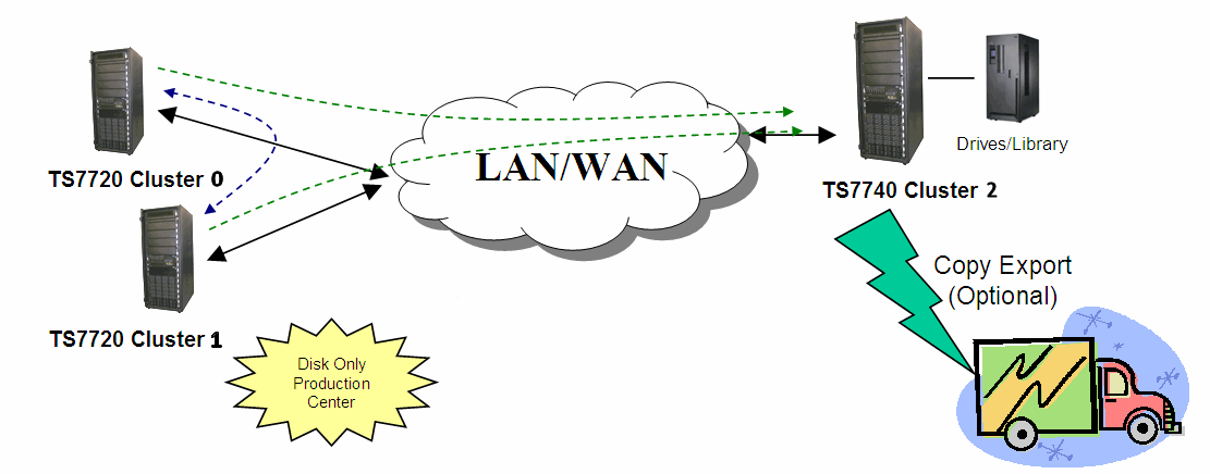
Figure 10-15 Three-cluster high availability and disaster recovery with two TS7720s and one TS7740
Another variation of this model uses a TS7720 and a TS7740 for the production site as shown in Figure 10-16, both replicating to a remote TS7740.

Figure 10-16 Three-cluster high availability and disaster recovery with two TS7740s and one TS7720
In both models, if a TS7720 reaches the upper threshold of utilization, the oldest data, which has already been replicated to the TS7740, is removed from the TS7720 cache.
In the example shown in Figure 10-16, you can have particular workloads favoring the TS7740, and others favoring the TS7720, suiting a specific workload to the cluster best equipped to perform it.
Copy Export (shown as optional in both figures) can be used to have a second copy of the migrated data, if required.
Four-cluster grid
A four-cluster grid that can have both sites for dual purposes is described. Both sites are equal players within the grid, and any site can play the role of production or disaster recovery, as required.
Dual production and disaster recovery
In this model, you have dual production and disaster recovery sites. Although a site can be labeled as a high availability pair or disaster recovery site, they are equivalent from a technology standpoint and functional design. In this example, you have two production sites within metro distances and two remote disaster recovery sites within metro distances between them. This configuration delivers the same capacity as a two-cluster grid configuration, with the high availability of a four-cluster grid. See Figure 10-17.

Figure 10-17 Four-cluster high availability and disaster recovery
You can have host workload balanced across both clusters (Cluster 0 and Cluster 1 in Figure 10-17). The logical volumes written to a particular cluster are only replicated to one remote cluster. In Figure 10-17, Cluster 0 replicates to Cluster 2 and Cluster 1 replicates to Cluster 3. This “partitioning” is accomplished by using copy policies. For the described behavior, copy mode for Cluster 0 is RNDN and for Cluster 1 is NRND.
This configuration delivers high availability at both sites, production and disaster recovery, without four copies of the same tape logical volume throughout the grid.
Figure 10-18 shows the four-cluster grid reaction to a cluster outage. In this example, Cluster 0 goes down due to an electrical power outage. You lose all logical drives emulated by Cluster 0. The host uses the remaining addresses emulated by Cluster 1 for the entire production workload.

Figure 10-18 Four-cluster grid high availability and disaster recovery - Cluster 0 outage
During the outage of Cluster 0 in the example, new jobs for write only use one half of the configuration (the unaffected “partition” in the lower part of the picture). Jobs for read can access content in all available clusters. When power is normalized at the site, Cluster 0 powers up and rejoin the grid, reestablishing the original balanced configuration.
In a disaster recovery situation, the backup host in the disaster recovery site operates from the second high availability pair, which is the pair of Cluster 2 and Cluster 3 in Figure 10-20 on page 723. In this case, copy policies can be DNRN for Cluster 2 and NDNR for Cluster 3, reversing the direction of the replication so that it is the opposite of the green arrows in Figure 10-18 on page 709.
Selective write protect for disaster recovery testing
This function allows clients to emulate disaster recovery events by running test jobs at a disaster recovery (DR) location within a TS7700 grid configuration, allowing volumes only within specific categories to be manipulated by the test application. This prevents any changes to production-written data. This is accomplished by excluding up to 16 categories from the cluster’s write-protect enablement. When a cluster is write-protect-enabled, all volumes that are protected cannot be modified or have their category or storage construct names modified. As in the TS7700 write-protect setting, the option is grid partition scope (a cluster) and configured through the MI. Settings are persistent and saved in a special repository.
Also, the new function allows for any volume assigned to one of the categories contained within the configured list to be excluded from the general cluster’s write-protect state. The volumes assigned to the excluded categories can be written to or have their attributes modified. In addition, those scratch categories that are not excluded can optionally have their Fast Ready characteristics ignored, including Delete Expire and hold processing, allowing the disaster recovery test to mount volumes as private that the production environment has since returned to scratch (they are accessed as read-only).
One exception to the write protect is those volumes in the insert category. To allow a volume to be moved from the insert category to a write-protect-excluded category, the source category of insert cannot be write-protected. Thus, the insert category is always a member of the excluded categories.
Be sure that you have enough scratch space when Expire Hold processing is enabled to prevent the reuse of production scratched volumes when planning for a DR test. Suspending the volumes’ return-to-scratch processing during the disaster recovery test is also advisable.
Because selective write protect is a cluster-wide function, separated DR drills can be conducted simultaneously within one multicluster grid, with each cluster having its own independent client-configured settings.
See 10.1, “TS7700 Virtualization Engine grid failover principles” on page 686 for more details.
10.5 Copy Export overview and Considerations
Copy Export provides a function to allow a copy of selected logical volumes written to the TS7700 Virtualization Engine to be removed and taken offsite for disaster recovery purposes. In addition, because the data is a copy of the logical volumes, the volumes remain intact and are still accessible by the production system.
Control of Copy Export
Storage Group and Management Class constructs are defined to use separate pools for the primary and secondary copies of the logical volume. The existing Management Class construct, which is part of Advanced Policy Management (APM), is used to create a second copy of the data to be Copy Exported. The Management Class actions are configured through the TS7700 Virtualization Engine MI. An option on the MI window allows designation of a secondary pool as a Copy Export pool. As logical volumes are written, the secondary copy of the data is pre-migrated to stacked volumes in the Copy Export pool.
Workflow of a Copy Export process
Typically, you run the Copy Export operation on a periodic basis. Because the purpose is to get a copy of the data offsite for disaster recovery purposes, performing it soon after the data is created minimizes the time for the recovery point objective (RPO).
When the time comes to initiate a Copy Export, a Copy Export job is run from the production host. The TS7740 Virtualization Engine pre-migrates any logical volumes in the Copy Export pool that have not been pre-migrated. Any new logical volumes written after the Copy Export operation is initiated is not included in the Copy Export set of physical volumes. The TS7740 Virtualization Engine then writes a complete TS7740 Virtualization Engine database to each of the physical volumes in the Copy Export set.
During a Copy Export operation, all of the physical volumes with active data on them in a specified secondary pool are removed from the library associated with the TS7740 Virtualization Engine. Only the logical volumes that are valid on that TS7740 Virtualization Engine are considered during the execution of the operation. Logical volumes currently mounted during a Copy Export operation are excluded from the export set as are any volumes that are not currently in the TVC of the export cluster.
The host that initiates the Copy Export operation first creates a dedicated export list volume on the TS7740 Virtualization Engine that runs the operation. The export list volume contains instructions regarding the execution of the operation and a reserved file that the TS7740 Virtualization Engine uses to provide completion status and export operation information. As part of the Copy Export operation, the TS7740 Virtualization Engine creates response records in the reserved file that list the logical volumes exported and the physical volumes on which they reside. This information can be used as a record for the data that is offsite. The TS7740 Virtualization Engine also writes records in the reserved file on the export list volume that provide the status for all physical volumes with a state of Copy Exported.
The Copy Export job can specify whether the stacked volumes in the Copy Export set must be ejected immediately or placed into the export-hold category. When Copy Export is used with the export-hold category, you need to manually request that the export-hold volumes be ejected. The choice to eject as part of the Copy Export job or to eject them later from the export-hold category is based on your operational procedures. The ejected Copy Export set is then transported to a disaster recovery site or vault. Your RPO determines the frequency of the Copy Export operation.
10.5.1 General considerations for Copy Export
Consider the following information when you are planning to use the Copy Export function for disaster recovery:
•Specific logical volumes are not specified as part of a Copy Export operation. Instead, all valid logical volumes on the physical volumes in the specified secondary pool are considered for export. After the first time that Copy Export is performed for a pool, the logical volumes that will be exported are the ones for that pool that have been newly written or modified since the last export began. Previously exported volumes that have not been changed is not exported. For recovery, all exported physical volumes that still contain active data from a source TS7700 need to be included because not all of the logical volumes that are created are going to be on the last set exported.
•The primary copy of the logical volumes exported remains in the inventory of the TS7700 grid. Exported volumes are always copies of volumes still in the TS7700.
•Only those logical volumes assigned to the secondary pool specified in the export list file volume that are resident on a physical volume of the pool or in the cache of the TS7700 performing the export operation is considered for export. For a grid configuration, if a logical volume is to be copied to the TS7700 that is performing the Copy Export operation, but that copy had not yet completed when the export is initiated, it is not included in the current export operation.
•Logical volumes to be exported that are resident only in the cache and not mounted when the Copy Export operation is initiated will be copied to stacked volumes in the secondary pool as part of the Copy Export operation.
•Any logical volume assigned to the specified secondary pool in the TS7700 after the Copy Export operation is initiated is not part of the export and is written to a physical volume in the pool but is not exported. This includes host-sourced and copy-sourced data.
•Volumes that are currently mounted cannot be Copy Exported.
•Only one Copy Export operation can be performed at a time.
•If the TS7700 cannot access the primary version of a logical volume designated for Copy Export and the secondary version is in a pool also defined for Copy Export, that secondary version is made inaccessible and the mount fails, regardless of whether that secondary pool is involved in the current Copy Export operation. When a Copy Export operation is not being performed, if the primary version of a logical volume cannot be accessed and a secondary version exists, the secondary becomes the primary.
•The library associated with the TS7700 running the Copy Export operation must have an I/O station feature for the operation to be accepted. Empty the I/O station before running Copy Export and prevent it from going to the full state.
•A minimum of four physical tape drives must be available to the TS7700 for the Copy Export operation to be performed. The operation is terminated by the TS7700 when fewer than four physical tape drives are available. Processing for the physical stacked volume in progress when the condition occurred is completed and the status file records reflect what was completed before the operation was ended.
•Copy Export and the insertion of logical volumes are mutually exclusive functions in a TS7700 or grid.
•Only one secondary physical volume pool can be specified per export operation, and it must have been previously defined as a Copy Export pool.
•The export list file volume cannot be assigned to the secondary copy pool that is specified for the operation. If it is, the Copy Export operation fails.
•If a scratch physical volume is needed during a Copy Export operation, the secondary physical volume pool must have an available scratch volume or access to borrow one for the operation to continue. If a scratch volume is not available, the TS7700 indicates this through a console message and waits for up to 60 minutes. If a scratch volume is not made available to the secondary physical volume pool within 60 minutes, the Copy Export operation is ended.
•During execution, if the TS7700 determines that a physical volume assigned to the specified secondary pool contains one or more primary logical volumes, that physical volume and any secondary logical volumes on it are excluded from the Copy Export operation.
•To minimize the number of physical tapes used for Copy Export, use the highest capacity media and physical drive format that is compatible with the recovery TS7700. You might also want to reduce the number of concurrent tape devices that the TS7700 uses when copying data from cache to the secondary copy pool used for Copy Export.
•All copy-exported volumes that are exported from a source TS7700 must be placed in a library for recovery. The source TS7700 limits the number of physical volumes that can be Copy Exported. The default limit is 2,000 per TS7700 to ensure that they all fit into the receiving library. This value can be adjusted to a maximum of 10,000 volumes.
•The recovery TS7700 must have physical tape drives that are capable of reading the physical volumes from a source TS7700. If a source TS7700 writes the volumes using the native E05 format, the recovery TS7700 must also have 3592-E05 drives running in native format mode. If the exporting pool on the source TS7700 is set up to encrypt the data, the recovery TS7700 must also be set up to handle encrypted volumes and have access to the encryption key manager with replicated keys from the production site. If the source TS7700 writes the volumes in J1A or emulated J1A mode, any 3592 model drive in the recovery TS7700 can read the data.
•The recovery TS7700 cannot contain any previous data, and a client-initiated recovery process cannot merge data from more than one source TS7700 together. As a part of the Copy Export Recovery, an option is provided to erase any previous data on the TS7700. This allows a TS7700 that is used for disaster recovery testing to be reused for testing of a different source TS7700’s data.
•For the secondary pool used for Copy Export, the designated reclaim pool must be the same value as the secondary volume pool.
|
Note: If the reclaim pool for the Copy Export secondary pool is the same as either the Copy Export primary pool or its reclaim pool, the primary and backup copies of a logical volume can exist on the same physical tape.
|
10.5.2 Copy Export grid considerations
Copy Export is supported in both grid and stand-alone environments. You need to remember several considerations that are unique to the grid environment.
Performing Copy Export
The first consideration relates to performing Copy Export. In a grid configuration, a Copy Export operation is performed against an individual TS7700, not across all TS7700 Virtualization Engines. Set up Copy Export in a grid plan based on the following guidelines:
•When using the Copy Export acceleration (LMTDBPVL) option, the database backup is appended only to the first two and the last two volumes that are exported. These corresponding tapes containing database backup are selected and listed in the alphabetical order of the physical tape VOLSER. If the export acceleration (LMTDBPVL) option was set and there is a failure appending the DB backup, a different physical volume is selected to contain the database backup so that four physical volumes have the DB backup.
•Decide which TS7700 in a grid configuration is going to be used to export a specific set of data. Although you can set up more than one TS7700 to export data, only the data from a single source TS7700 can be used in the recovery process. You cannot merge copy-exported volumes from more than one source TS7700 in the recovery TS7700.
•For each specific set of data to export, define a Management Class name. On the TS7700 that is used to export that data, define a secondary physical volume pool for that Management Class name and also ensure that you indicate that it is an export pool. Although you need to define the Management Class name on all TS7700s in the grid configuration, specify only the secondary physical volume pool on the TS7700 that is to perform the export operation. Specifying it on the other TS7700s in the grid configuration does not interfere with the Copy Export operation, but it is a waste of physical volumes. The exception to this approach is if you want one of the TS7700s in the grid configuration to have a second physical copy of the data if the primary copies on other TS7700s are inaccessible.
•While you are defining the Management Class name for the data, also ensure that the TS7700 to perform the export operation has a copy policy specifying that it is to have a copy.
•When the Copy Export operation is run, the export list file volume must be valid only on the TS7700 performing the operation. You need to define a unique Management Class name to be used for the export list file volume. For that Management Class name, you need to define its copy policy so that a copy is only on the TS7700 that is to perform the export operation. If the VOLSER specified for the export list file volume when the export operation is initiated is resident on more than one TS7700, the Copy Export operation fails.
|
Tip: If the Management Class specified for the Copy Export operation is defined to more than one cluster, the Copy Export fails and the following CBR message is displayed:
CBR3726I FUNCTION INCOMPATIBLE ERROR CODE 32 FROM LIBRARY XXX FOR VOLUME xxxxxx.
X'32' There is more than one valid copy of the specified export list volume in the TS7700 grid configuration.
|
Consider this Copy Export example:
a. A Copy Export with the export list volume EXP000 is initiated from a host connected to the C0, and the Copy Export runs on the C2.
b. The copy mode of EXP000 must be [N,N,D] or [N,N,R], indicating that the only copy of EXP000 exists on C2.
c. If Copy Policy Override is activated on the C0 and the Copy Export is initiated from the host attached to C0, a copy of EXP000 is created both on the C0 and C1.
d. The grid detects that a copy of EXP000 exists on two clusters (C0 and C2) and does not start the Copy Export.
e. Copy Export fails.
For example, assume that the TS7700 that is to perform the Copy Export operation is Cluster 1. The pool on that cluster to export is pool 8. You need to set up a Management Class for the data that is to be exported so that it has a copy on Cluster 1 and a secondary copy in pool 8. To ensure that the data is on that cluster and is consistent with the close of the logical volume, you want to have a copy policy of Rewind Unload (RUN). You define the following information:
•Define a Management Class, for example, MCCEDATA, on Cluster 1:
Secondary Pool 8
Cluster 0 Copy Policy RUN
Cluster 1 Copy Policy RUN
•Define this same Management Class on Cluster 0 without specifying a secondary pool.
•To ensure that the export list file volume gets written to Cluster 1 and only exists there, define a Management Class, for example, MCELFVOL, on Cluster 1:
Cluster 0 Copy Policy No Copy
Cluster 1 Copy Policy RUN
•Define this Management Class on Cluster 0:
Cluster 0 Copy Policy No Copy
Cluster 1 Copy Policy RUN
A Copy Export operation can be initiated through any virtual tape drive in the TS7700 grid configuration. It does not have to be initiated on a virtual drive address in the TS7700 that is to perform the Copy Export operation. The operation is internally routed to the TS7700 that has the valid copy of the specified export list file volume. Operational and completion status is broadcast to all hosts attached to all of the TS7700s in the grid configuration.
It is assumed that Copy Export is performed regularly, and logical volumes whose copies were not complete when a Copy Export was initiated will be exported the next time that Copy Export is initiated. You can check the copy status of the logical volumes on the TS7700 that is to perform the Copy Export operation before initiating the operation by using the Volume Status function of the BVIR facility. You can then be sure that all critical volumes are exported during the operation.
Performing Copy Export Recovery
The next consideration relates to how Copy Export Recovery is performed. Copy Export Recovery is always to a stand-alone TS7700. As part of a client-initiated recovery process, the recovery TS7700 processes all grid-related information in the database, converting it to look like a single TS7700. This conversion means that the recovery TS7700 will have volume ownership of all volumes. It is possible that one or more logical volumes will become inaccessible because they were modified on a TS7700 other than the one that performed the Copy Export operation, and the copy did not complete before the start of the operation. Remember that each copy-exported physical volume remains under the management of the TS7700 from which it was exported.
Normally, you return the empty physical volumes to the library I/O station that associated with the source TS7700 and reinsert them. They are then reused by that TS7700. If you want to move them to another TS7700, whether in the same grid configuration or another, consider two important points:
•Ensure that the VOLSER ranges you define for that TS7700 match the VOLSERs of the physical volumes that you want to move.
•To have the original TS7700 stop managing the copy-exported volumes, enter the following command from the host: LIBRARY REQUEST,libname,COPYEXP,volser,DELETE
10.5.3 Reclaim process for Copy Export physical volumes
The physical volumes exported during a Copy Export operation continue to be managed by the source TS7740 Virtualization Engine regarding space management. As logical volumes that are resident on the exported physical volumes expire, are rewritten, or otherwise invalidated, the amount of valid data on a physical volume decreases until the physical volume becomes eligible for reclamation based on your provided criteria for its pool. Exported physical volumes that are to be reclaimed are not brought back to the source TS7740 Virtualization Engine for processing. Instead, a new secondary copy of the remaining valid logical volumes is made using the primary logical volume copy as a source.
Figure 10-19 shows how the Reclaim Threshold Percent is set in Physical Volume Properties.

Figure 10-19 Reclaim Threshold Percent is set in Physical Volume Properties
The next time that the Copy Export operation is performed, the physical volumes with the new copies are also exported. The physical volumes that were reclaimed (which are offsite) no longer are considered to have valid data and can be returned to the source TS7740 Virtualization Engine to be used as new scratch volumes.
|
Tip: If a Copy Export hold volume is reclaimed while it is still present in the tape library, it is automatically moved back to the common scratch pool (or the defined reclamation pool) after the next Copy Export operation completes.
|
Monitoring for Copy Export data
The Bulk Volume Information Retrieval (BVIR) function can also be used to obtain a current list of exported physical volumes for a secondary pool. For each exported physical volume, information is available on the amount of active data that each cartridge contains.
10.5.4 Copy Export process messages
During the execution of the Copy Export operation, the TS7700 sends informational messages to its attached hosts. These messages are in the syslog and are shown in Table 10-1.
|
Note: All messages are prefaced with CBR3750I
|
Table 10-1 SYSLOG messages from the library
|
Message description
|
Action needed
|
|
E0000 EXPORT OPERATION STARTED FOR EXPORT LIST VOLUME XXXXXX
This message is generated when the TS7700 begins the Copy Export operation.
|
None.
|
|
E0005 ALL EXPORT PROCESSING COMPLETED FOR EXPORT LIST VOLUME XXXXXX
This message is generated when the TS7700 completes an export operation.
|
None.
|
|
E0006 STACKED VOLUME YYYYYY FROM LLLLLLLL IN EXPORT-HOLD
This message is generated during Copy Export operations when an exported stacked volume ‘YYYYYY’ has been assigned to the export-hold category. The ‘LLLLLLLL’ field is replaced with the distributed library name of the TS7700 performing the export operation.
|
None.
|
|
E0006 STACKED VOLUME YYYYYY FROM LLLLLLLL IN EJECT
This message is generated during Copy Export operations when an exported stacked volume ‘YYYYYY’ has been assigned to the eject category. The physical volume will be placed in the convenience I/O station. The ‘LLLLLLLL’ field is replaced with the distributed library name of the TS7700 performing the export operation.
|
Remove ejected volumes from the convenience I/O station.
|
|
E0013 EXPORT PROCESSING SUSPENDED, WAITING FOR SCRATCH VOLUME
This message is generated every 5 minutes when the TS7700 needs a scratch stacked volume to continue export processing and there are none available.
|
Make one or more physical scratch volumes available to the TS7700 performing the export operation. If the TS7700 does not get access to a scratch stacked volume in 60 minutes, the operation is ended.
|
|
E0014 EXPORT PROCESSING RESUMED, SCRATCH VOLUME MADE AVAILABLE
This message is generated when, after the export operation was suspended because no scratch stacked volumes were available, scratch stacked volumes are again available and the export operation can continue.
|
None.
|
|
E0015 EXPORT PROCESSING TERMINATED, WAITING FOR SCRATCH VOLUME
This message is generated when the TS7700 ends the export operation because scratch stacked volumes were not made available to the TS7700 within 60 minutes of the first E0013 message.
|
Operator must make more TS7700 stacked volumes available, perform analysis of the Status file on the export list file volume, and reissue the export operation.
|
|
E0016 COPYING LOGICAL EXPORT VOLUMES FROM CACHE TO STACKED VOLUMES
This message is generated when the TS7700 begins, and every 10 minutes during, the process of copying logical volumes that are only resident in the Tape Volume Cache to physical volumes in the specified secondary physical volume pool.
|
None.
|
|
E0017 COMPLETED COPY OF LOGICAL EXPORT VOLUMES TO STACKED VOLUMES
This message is generated when the TS7700 completes the copy of all needed logical volumes from cache to physical volumes in the specified secondary physical volume pool.
|
None.
|
|
E0018 EXPORT TERMINATED, EXCESSIVE TIME FOR COPY TO STACKED VOLUMES
The export process has been ended because one or more cache resident-only logical volumes needed for the export were unable to be copied to physical volumes in the specified secondary physical volume pool within a 10-hour period from the beginning of the export operation.
|
Call for IBM support.
|
|
E0019 EXPORT PROCESSING STARTED FOR POOL XX
This message is generated when the TS7700 export processing for the specified secondary physical volume pool XX.
|
None.
|
|
E0020 EXPORT PROCESSING COMPLETED FOR POOL XX
This message is generated when the TS7700 completes processing for the specified secondary physical volume pool XX.
|
None.
|
|
E0021 DB BACKUP WRITTEN TO STACKED VOLUMES, PVOL01, PVOL02, PVOL03, PVOL04
(where PVOL01, PVOL02, PVOL03, and PVOL04 are the physical volumes to which the database backup was appended).
This message is generated if the Copy Export acceleration (LMTDBPVL) option was selected on the export.
|
None.
|
|
E0022 EXPORT RECOVERY STARTED
The export operation has been interrupted by a TS7700 error or a power off condition. When the TS7700 is restarted, it attempts recovery of the operation.
|
None.
|
|
E0023 EXPORT RECOVERY COMPLETED
The recovery attempt for interruption of an export operation has been completed.
|
Perform analysis of the Status file on the export list file volume and reissue the export operation, if necessary.
|
|
E0024 XXXXXX LOGICAL VOLUME WITH INVALID COPY ON LLLLLLLL
This message is generated when the TS7700 performing the export operation has determined that one or more (XXXXXX) logical volumes that are associated with the auxiliary storage pool specified in the export list file do not have a valid copy resident on the TS7700. The ‘LLLLLLLL’ field is replaced by the distributed library name of the TS7700 performing the export operation. The export operation continues with the valid copies.
|
When the export operation completes, perform analysis of the Status file on the Export List File volume to determine the logical volumes that were not exported. Ensure that they have completed their copy operations and then perform another export operation.
|
|
E0025 PHYSICAL VOLUME XXXXXX NOT EXPORTED, PRIMARY COPY FOR YYYYYY UNAVAILABLE
This message is generated when the TS7700 detected a migrated-state logical volume ‘YYYYYY’ with an unavailable primary copy. The physical volume ‘XXXXXX’ on which the secondary copy of the logical volume ‘YYYYYY’ is stored was not exported.
This message is added at code level R1.7.
|
The logical volume and the physical volume will be eligible for the next Copy Export operation after the logical volume is mounted and unmounted from the host. An operator intervention is also posted.
|
|
E0026 DB BACKUP WRITTEN TO ALL OF STACKED VOLUMES
This message is generated when Copy Export acceleration (LMTDBPVL) option is not selected.
|
None.
|
When a stacked volume associated with a Copy Export operation is ejected from a library (placed in export-hold or is physically ejected from the library), you see status message E0006, which is sent by the library (see Table 10-1 on page 717). Removable Media Management (RMM) intercepts this message and performs one of these actions:
•If the stacked volume is predefined to RMM, RMM marks the volume as “ejected” or “in-transit” and sets the movement/store date associated with the stacked volume.
•If the stacked volume is not predefined to RMM and the STACKEDVOLUME(YES) option in RMM is specified, RMM automatically adds the stacked volume to its control data set (CDS).
To have DFSMSrmm policy management manage the retention and movement for volumes created by Copy Export processing, you must define one or more volume Vital Record Specifications (VRS). For example, assume that all Copy Exports are targeted to a range of volumes STE000 - STE999. You can define a VRS as shown in Example 10-1.
Example 10-1 VRS definition
RMM AS VOLUME(STE*) COUNT(99999) LOCATION(location)
As a result, all matching stacked volumes that are set in AUTOMOVE have their destination set to the required location and your existing movement procedures can be used to move and track them.
In addition to the support listed, a copy-exported stacked volume can become eligible for reclamation based on the reclaim policies defined for its secondary physical volume pool or through the Host Console Request function (LIBRARY REQUEST). When it becomes eligible for reclamation, the exported stacked volume no longer contains active data and can be returned from its offsite location for reuse.
For users that use DFSMSrmm, when you have stacked volume support enabled, DFSMSrmm automatically handles and tracks the stacked volumes created by Copy Export. However, there is no way to track which logical volume copies are on the stacked volume. Retain the updated export list file, which you created and the library updated, so that you have a record of the logical volumes that were exported and on what exported stacked volume they reside.
For more information and error messages related to the Copy Export function in RMM, see the z/OS DFSMSrmm Implementation and Customization Guide, SC23-6874.
10.6 Implementing and running Copy Export
Implementing and running Copy Export are described. For more information and error messages that relate to the Copy Export function, see the IBM Virtualization Engine TS7700 Series Copy Export Function User’s Guide, which is available at:
10.6.1 Setting up data management definitions
To set up the data management definitions, perform the following steps:
1. Decide the Management Class construct name (or names).
As part of the plan for using the Copy Export function, you must decide on at least one Management Class construct name. A preferred practice is to make the name meaningful and relate to the type of data to be on the pool or the location where the data is sent. For example, if the pool is used to send data to the primary disaster recovery site in Atlanta, a name like “MCPRIATL” can be used. “MC” for Management Class, “PRI” indicate that it is for the primary recovery site, and “ATL” indicates Atlanta. Up to an eight-character name can be defined.
2. Define the Management Class names to DFSMS.
After the Management Class names are selected, the names must be defined to DFSMS and to the TS7700. For details about defining the Management Class in DFSMS, see z/OS DFSMSdfp Storage Administration, SC23-6868.
None of the settings are used for system-managed tape. All settings associated with a Management Class name are defined through the TS7700, not the DFSMS windows.
3. Define the Management Class names to the TS7700.
You must also define the Management Class names on the TS7700 because you are not using the Default Management Class settings for Copy Export volumes. Define a Secondary Pool for the copies to be exported.
See “Management Classes window” on page 385 for details of how to add a Management Class.
4. Define the VOLSER ranges for the 3592 media.
You must define the VOLSER range (or ranges) for the physical volumes to use for Copy Export if you plan to use a specific VOLSER range. Ensure that you define the same pool that you used in the Management Class definition as the Home Pool for this VOLSER range.
For the physical volumes that you use for Copy Export, defining a specific VOLSER range to be associated with a secondary pool on a source TS7700 can simplify the task of knowing the volumes to use in recovery and of returning a volume that no longer has active data on it to the TS7700 that manages it.
See“Defining VOLSER ranges for physical volumes” on page 474 for details about how to define the VOLSER ranges.
5. Define the characteristics of the physical volume pools used for Copy Export.
For the pool or pools that you plan to use for Copy Export and that you have specified previously in the Management Class definition, and, optionally, in the VOLSER range definition, select Copy Export in the Export Pool field.
See “Defining physical volume pools in the TS7740” on page 475 for more information about how to change the physical volume pool properties.
6. Code or modify the Management Class ACS routine.
Add selection logic to the Management Class ACS routine to assign the new Management Class name, or names, as appropriate.
7. Activate the new construct names and ACS routines.
Before new allocations are assigned to the new Management Class, the Source Control Data Set (SCDS) with the new Management Class definitions and ACS routines must be activated by using the SETSMS SCDS command.
10.6.2 Validating before activating the Copy Export function
Before the logical volumes are exported, you must perform several general validations. Before you initiate the operation, check that the TS7700 Virtualization Engine has the required physical drives and scratch physical volume resources. Verify that the TS7700 Virtualization Engine is not near the limit of the number of physical volumes that can have a status of Copy Exported and modify the value, if required. Depending on your production environment, you might want to automate these validation steps.
Follow these validation steps:
1. Determine whether data is in an older format. If you had migrated from a B10 or B20 VTS to the TS7700 Virtualization Engine by using the outboard migration method, you might have data that is still in the older VTS format. The TS7700 Virtualization Engine cannot export data in the old format, so you must determine whether any of the data to export was written with the old format.
2. Validate that the TS7700 Virtualization Engine has at least four available physical tape drives and one in IDLE status. You can use the Library Request host console command that specifies the PDRIVE request. This returns the status of all physical drives attached to the TS7700 Virtualization Engine. If fewer than the required numbers of physical drives are available, you must call for service to repair drives before you perform the Copy Export operation.
See Example 10-2 for the output of the PDRIVE request. This command is only valid when run against a distributed library.
Example 10-2 Data returned by the PDRIVE request
LI REQ,BARR03A,PDRIVE
CBR1020I PROCESSING LIBRARY COMMAND: REQ,BARR03A,PDRIVE.
CBR1280I LIBRARY BARR03A REQUEST. 768
KEYWORDS: PDRIVE
---------------------------------------------------------------
PHYSICAL DRIVES V2
SERIAL NUM TYPE MODE AVAIL ROLE POOL PVOL LVOL
0000013D0531 3592E07 E07E Y MIGR 03 JBB829 635219
0000013D0507 3592E07 E07E Y IDLE 02 JBB839
0000013D0530 3592E07 E07E Y IDLE 01 JBB841
0000013D0534 3592E07 E07E Y MIGR 03 JBB825 635083
0000013D0511 3592E07 E07E Y IDLE 03 JBB836
0000013D0551 3592E07 E07E Y MIGR 02 JBB813 624305
0000013D0527 3592E07 E07E Y MIGR 02 JBB840 635166
0000013D0515 3592E07 E07E Y IDLE 01 JBB835
0000013D0510 3592E07 E07E Y IDLE 03 JBB826
In the response shown in Example 10-2 on page 721, you can see the following information:
– Nine drives are defined.
– All nine drives are available (AVAIL=Y).
– The ROLE column describes which drive is performing. The following values can be indicated:
• IDLE: The drive is not in use for another role or is not mounted.
• SECE: The drive is being used to erase a physical volume.
• MIGR: The drive is being used to copy a logical volume from the TVC to a physical volume. In this display, logical volume 635219 is being copied to physical volume JBB829.
• RECA: The drive is being used to recall a logical volume from a physical volume to the TVC.
• RCLS: The drive is being used as the source of a reclaim operation.
• RCLT: The drive is being used as the target of a reclaim operation.
3. Check that the pool to be exported has sufficient scratch physical volumes and that the TS7700 Virtualization Engine is under the volume limit for copy-exported volumes in all pools. The limit by default is a total of 2,000 volumes but this limit can be modified in the SETTINGS option of the TS7000 MI with a maximum of 10,000 volumes. You can use the Library Request host console command that specifies the POOLCNT request. See Example 10-3 for the response to the LI REQ, <library-ID>, POOLCNT command.
Example 10-3 Data returned from POOLCNT command
LI REQ,BARR68A,POOLCNT
CBR1020I PROCESSING LIBRARY COMMAND: REQ,BARR68A,POOLCNT.
CBR1280I LIBRARY BARR68A REQUEST. 919
KEYWORDS: POOLCNT
--------------------------------------------------------------------
PHYSICAL MEDIA COUNTS V2
POOL MEDIA EMPTY FILLING FULL ERASE ROR UNAVAIL CXPT
0 JA 164
0 JJ 38
1 JA 2 6 12 0 0 1 0
9 JJ 0 4 22 0 0 0 45
Pool 0 is the Common Scratch Pool. Pool 9 is the pool that is used for Copy Export in this example. Example 10-3 shows the command POOLCNT. The response is listed per pool:
– The media type used for each pool
– The number of empty physical volumes that are available for Scratch processing
– The number of physical volumes in the filling state
– The number of full volumes
– The number of physical volumes that have been reclaimed, but need to be erased
– The number of physical volumes in read-only recovery state
– The number of volumes unavailable or in a destroyed state (1 in Pool 1)
– The number of physical volumes in the copy-exported state (45 in Pool 9)
Use the MI to modify the maximum-allowed number of volumes in the copy-exported state (Figure 10-20).

Figure 10-20 Maximum allowable number of volumes in copy-exported state
You must determine when you usually want to start the Copy Export operation. Thresholds might be the number of physical scratch volumes or other values that you define. These thresholds can even be automated by creating a program that interprets the output from the Library Request commands PDRIVE and POOLCNT, and acts based on the required numbers.
For more information about the Library Request command, see 8.4.3, “Host Console Request function” on page 534.
10.6.3 Running the Copy Export operation
To begin the Copy Export process, create an export list volume that provides the TS7700 Virtualization Engine with information about which data to export and the options to use during the operation (Figure 10-21 on page 725).
If you use a multicluster grid, be sure to create the export list volume only on the same TS7700 Virtualization Engine that is used for Copy Export, but not on the same physical volume pool that is used for Copy Export. If more than one TS7700 Virtualization Engine in a multicluster grid configuration contains the export list volume, the Copy Export operation fails.
Ensure that all volumes that are subject for copy export are in the TVC of the TS7740 where the copy export will be run. If there are copies from other clusters that have not been processed, you can promote them in the copy queue. Use the HCR command with the option “COPY,KICK” to do so:
LI REQ,distributed library,LVOL,A08760,COPY,KICK
Complete these steps to run the Copy Export operation:
1. Create the export list volume JCL (Example 10-4).
Example 10-4 Sample JCL to create an export list volume of Pool 9
//****************************************
//* FILE 1: EXPORT LIST
//****************************************
//STEP1 EXEC PGM=IEBGENER
//SYSPRINT DD SYSOUT=*
//SYSIN DD DUMMY
//SYSUT2 DD DSN=HILEVELQ.EXPLIST,
// UNIT=VTS1,DISP=(NEW,KEEP),LABEL=(1,SL),
// VOL=(,RETAIN),
// DCB=(RECFM=FB,BLKSIZE=80,LRECL=80,TRTCH=NOCOMP)
//SYSUT1 DD *
EXPORT LIST 03
EXPORT PARAMETERS PHYSICAL POOL TO EXPORT:09
OPTIONS1,COPY,EJECT
/*
//****************************************
//* FILE 2: RESERVED FILE
//****************************************
//STEP2 EXEC PGM=IEBGENER,COND=(4,LT)
//SYSPRINT DD SYSOUT=*
//SYSIN DD DUMMY
//SYSUT2 DD DSN=HILEVELQ.RESERVED,MGMTCLAS=MCNOCOPY,
// UNIT=VTS1,DISP=(NEW,KEEP),LABEL=(2,SL),
// VOL=(,RETAIN,REF=*.STEP1.SYSUT2),
// DCB=*.STEP1.SYSUT2
//SYSUT1 DD *
RESERVED FILE
/*
//****************************************
//* FILE 3: EXPORT STATUS FILE
//****************************************
//STEP3 EXEC PGM=IEBGENER,COND=(4,LT)
//SYSPRINT DD SYSOUT=*
//SYSIN DD DUMMY
//SYSUT2 DD DSN=HILEVELQ.EXPSTATS,
// UNIT=VTS1,DISP=(NEW,CATLG),LABEL=(3,SL),
// VOL=(,,REF=*.STEP1.SYSUT2),
// DCB=*.STEP1.SYSUT2
//SYSUT1 DD *
EXPORT STATUS 01
/*
The information required in the Export List file is, as for BVIR, provided by writing a logical volume that fulfills the following requirements:
– That logical volume must have a standard label and contain three files:
• An Export List file, as created in step 1 in Example 10-4 on page 723. In this example, you are exporting Pool 09. Option EJECT in record 2 tells the TS7700 Virtualization Engine to eject the stacked volumes upon completion. With OPTIONS1,COPY, the physical volumes are placed in the export-hold category for later handling by an operator.
• A Reserved file, as created in step 2 in Example 10-4 on page 723. This file is reserved for future use.
• An Export Status file, as created in step 3 in Example 10-4 on page 723. In this file, the information is stored from the Copy Export operation. You must keep this file because it contains information related to the result of the Export process and must be reviewed carefully.
– All records must be 80 bytes in length.
– The Export List file must be written without compression. Therefore, you must assign a Data Class that specifies COMPACTION=NO or you can overwrite the Data Class specification by coding TRTCH=NOCOMP in the JCL.
|
Important: Ensure that the files are assigned a Management Class that specifies that only the local TS7700 Virtualization Engine has a copy of the logical volume. You can either have the ACS routines assign this Management Class, or you can specify it in the JCL. These files need to have the same expiration dates as the longest of the logical volumes you export because they must be kept for reference.
|
Figure 10-21 shows the setting of a Management Class on the MI for the export list volume in a multicluster grid configuration. RN means one copy locally at RUN (R) and no copy (NN) on the other cluster.
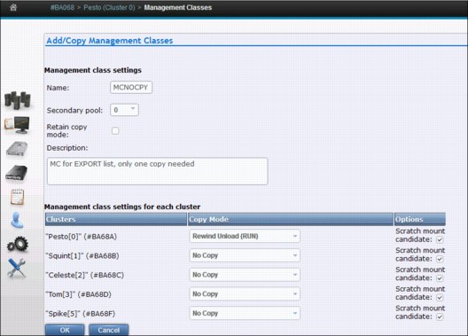
Figure 10-21 Management Class settings for the export list volume
2. The Copy Export operation is initiated by running the LIBRARY EXPORT command. In this command, logical VOLSER is a variable and is the logical volume used in creating the Export List file volume. The command syntax is shown in Example 10-5.
Example 10-5 Library export command
LIBRARY EXPORT,logical VOLSER
3. The host sends a command to the composite library. From there, it is routed to the TS7700 Virtualization Engine where the Export List VOLSER resides.
4. The running TS7700 Virtualization Engine validates the request, checking for required resources, and if all is acceptable, the Copy Export continues.
5. Logical volumes related to the exported pool that still are only in cache can delay the process. They are copied to physical volumes in the pool as part of the Copy Export execution.
6. Messages about the progress are sent to the system console. All messages are in the format shown in Example 10-6. See Table 10-1 on page 717 for explanation of Library Message Text,
Example 10-6 Library message format
CBR3750I Message from library library-name: message text.
After a successful completion, all physical tapes related to the export pool are ejected if the eject command was specified. The operator can empty the I/O station and transport the tapes to another location.
To obtain a list of the virtual volumes that were exported during the COPY EXPORT operation, use the Physical Volumes Details selection in the MI. Specify the volume or volumes that were written to during the EXPORT. Those volsers are listed in the CBR3750I messages on the syslog. Click Download List of Virtual Volumes.
Figure 10-22 shows the physical volume details.

Figure 10-22 Physical Volume Details selection for list of exported volumes
10.6.4 Canceling a Copy Export operation
Examine the export status file records to see what has been processed before the cancellation request. Any physical volumes that completed the export process must be processed as though the export operation had completed.
Many reasons exist for canceling a Copy Export operation:
•After initiating a Copy Export operation, you might realize that the pool being processed for export is incorrect.
•Other, more critical workloads must be run on the TS7700 Virtualization Engine and the extra impact of running the export operation is undesirable.
•A problem is encountered with the export that cannot be quickly resolved, for example, there are no physical scratch volumes available to add to the library.
•A problem is encountered with the library that requires it to be taken offline for service.
A request to cancel an export operation can be initiated from any host attached to the TS7700 Virtualization Engine subsystem by using one of the following methods:
•Use the host console command LIBRARY EXPORT,XXXXXX,CANCEL, where XXXXXX is the volume serial number of the Export List File Volume.
•Use the Program Interface of the Library Control System (LCS) external services CBRXLCS.
If an export operation must be canceled and there is no host attached to the TS7700 Virtualization Engine that can run the CANCEL command, you can cancel the operation through the TS7700 Virtualization Engine MI. After confirming the selection, a cancel request is sent to the TS7700 Virtualization Engine that is processing the Copy Export operation.
Regardless of whether the cancellation originates from a host or the MI, the TS7700 Virtualization Engine can process it in the following manner:
•If the processing of a physical volume has reached the point where it has been mounted to receive a database backup, the backup completes and the volume is placed in the export-hold or eject category before the cancel processing can continue. Status file records are written for all logical and physical volumes that completed export processing.
•All physical resources (drives, stacked volumes, and exported stacked volumes) are made available for normal TS7700 Virtualization Engine subsystem processing.
•A completion message is sent to all hosts attached to the TS7700 Virtualization Engine indicating that the export was canceled by a host request. The message contains information about how much export processing completed before the execution of the cancellation request.
10.6.5 Host completion message
At the completion of the Copy Export operation, a completion message is broadcast to all hosts attached to the TS7700 Virtualization Engine. For z/OS, console messages are generated that provide information about the overall execution status of the operation.
Messages differ depending on what the TS7700 Virtualization Engine encountered during the execution of the operation:
•If no errors or exceptions were encountered during the operation, message CBR3855I is generated. The message has the format shown in Example 10-7.
Example 10-7 CBR3855I message format
CBR3855I Export operation for logical list volume ‘volser’ in library ‘library-name’ completed successfully. Requested: ‘requested-number’ Exportable: ‘exportable-number’ Exported: ‘exported-number’ Stacked volumes: ‘stacked-number’ MBytes Exported: ‘MBytes-exported’ MBytes Moved: ‘MBytes-moved’
•If error or exceptions were encountered during the operation, message CBR3856I is generated. The message has the format shown in Example 10-8.
Example 10-8 CBR3856I message format
CBR3856I Export operation for logical list volume ‘volser’ in library ‘library-name’ completed with exceptions or errors. Requested: ‘requested-number’ Exportable: ‘exportable-number’ Exported: ‘exported-number’ Stacked volumes: ‘stacked-number’ MBytes Exported: ‘MBytes-exported’ MBytes Moved: ‘MBytes-moved’
If message CBR3856I is generated, examine the Export Status file to determine what errors or exceptions were encountered.
Either of the completion messages provides statistics about what was processed during the operation. The following statistics are reported:
•Requested-number: This is the number of logical volumes associated with the secondary volume pool specified in the export list file. Logical volumes associated with the specified secondary volume pool that were previously exported are not considered part of this count.
•Exportable-number: This is the number of logical volumes that are considered exportable. A logical volume is exportable if it is associated with the secondary volume pool specified in the export list file and it has a valid copy resident on the TS7700 Virtualization Engine performing the export. Logical volumes associated with the specified secondary volume pool that were previously exported are not considered to be resident in the TS7700 Virtualization Engine.
•Exported-number: This is the number of logical volumes that were successfully exported.
•Stacked-number: This is the number of physical volumes that were successfully exported.
•MBytes Exported: This is the number of MB contained in the logical volumes that were successfully exported. If the data on the logical volumes is compressed, the number includes the effect of compression.
|
Clarification: The number of megabytes (MB) exported is the sum of the MB integer values of the data stored on each Exported Stacked Volume. The MB integer value for each Exported Stacked Volume is the full count by bytes divided by 1,048,576 bytes. If the result is less than 1, the MB integer becomes 1, and if greater than 1 MB, the result is truncated to the integer value (rounded down).
|
•MBytes Moved: For Copy Export at code release level R1.4 and later, this value is 0.
It is possible that multiple physical cartridges are written to during the COPY EXPORT even if a small amount of data was exported. This is primarily due to the optimization of the operation by using multiple available drives.
10.7 Using Copy Export Recovery
The recovery process can be done in a test mode for DR testing purposes. This allows a test restore without compromising the contents of the Copy Export sets. An example of how to use a Copy Export Recovery process is provided.
|
Restriction: Clients can run a Copy Export Recovery process only in a stand-alone cluster. After the recovery process completes, you can create a multicluster grid by joining the grid with another stand-alone cluster. However, there is an IBM service offering to recover to an existing grid.
|
The following instructions for how to implement and run Copy Export Recovery also apply if you are running a DR test. If it is a test, it is specified in each step.
10.7.1 Planning and considerations for testing Copy Export Recovery
You must consider several factors when you prepare a recovery TS7700 Virtualization Engine for the Copy Export volumes. Copy Export Recovery can be run in various ways. The planning considerations for Copy Export Recovery are described.
Copy Export Recovery can be used to restore previously created and copy-exported tapes to a new, empty TS7740 cluster. The same subset of tapes can be used to restore a TS7740 in an existing grid if the new empty restore cluster replaces the source cluster that is no longer present.
This allows data that might have existed only within a TS7740 in a hybrid configuration to be restored while maintaining access to the still existing TS7720 clusters. This form of extended recovery must be carried out by IBM support personnel.
Client-initiated Copy Export Recovery
Client-initiated recovery restores copy-exported tapes to a stand-alone TS7740 for DR testing or as a recovery site. The considerations for Copy Export Recovery to a stand-alone TS7740 cluster, which can be prepared in advance, are described. The TS7700 Virtualization Engine and associated library that is to be used for recovery of the copy-exported logical volumes must meet the following requirements:
•The recovery TS7700 Virtualization Engine must have physical tape drives that match the capabilities of the source TS7700 Virtualization Engine, including encryption capability if the copy-exported physical volumes have been encrypted.
•If the source copy-exported volumes have been encrypted, the recovery TS7700 Virtualization Engine must have access to a key manager that has the encryption keys for the data.
•There must be enough library storage slots in the library associated with the recovery TS7700 Virtualization Engine to hold all of the copy-exported physical volumes from the source TS7700 Virtualization Engine.
•Only the copy-exported volumes from a single source TS7700 Virtualization Engine can be used in the recovery process.
•The recovery TS7700 Virtualization Engine cannot be part of a grid configuration.
•The recovery TS7700 Virtualization Engine must be configured as Cluster 0.
•The recovery TS7700 Virtualization Engine and its associated MI must be configured, have code loaded, and be in an online state to start the recovery.
•The code levels on the recovery TS7700 must be at the same or later code level as the source TS7700.
•If the recovery TS7700 Virtualization Engine is not empty of data (in the cache or the database), the Copy Export volumes must not be loaded into the attached library until the system has been emptied of data.
•If another TS7700 Virtualization Engine or native drives are on another partition of the TS3500 Tape Library, the other partition must not have any VOLSERS that overlap with the VOLSERS to be recovered (including both logical and physical volumes). If any conflicts are encountered during the recovery process, the VOLSERS that conflict cannot be recovered, a warning message is displayed in the recovery status window on the recovery TS7700 Virtualization Engine MI, and you cannot use the same library for both the source and recovery TS7700 Virtualization Engine.
•Other than the physical drive compatibility requirements listed, the source and recovery TS7700 Virtualization Engines can have different configuration features, such as different cache capabilities, performance enablement features, and so on.
•You must add scratch physical volumes to the recovery TS7700 Virtualization Engine even if you are only going to be reading data. A minimum of two scratch volumes per defined pool in the recovery TS7740 is needed to prevent the recovery TS7740 from entering the out-of-scratch state. In the out-of-scratch state, logical volume mounts are not allowed. When adding scratch physical volumes to the recovery TS7740, do so only after the recovery has been run and the recovery TS7740 is ready to be brought online to its attached hosts. Otherwise, their inventory records will be erased during the recovery process. Physical volumes that are part of the Copy Export set and are now empty cannot be counted as scratch. After the Copy Export Recovery is complete, and the recovery TS7740 Virtualization Engine is online to its hosts, you must insert logical volumes to be used as scratch volumes before you can write new data.
•If the recovery is for a real disaster (rather than only a test), verify that the actions defined for the storage management constructs that were restored during the recovery are the actions that you want to continue to use.
10.7.2 Performing Copy Export Recovery
Perform the following steps:
1. With the TS7740 and library in an online state, log in to the MI and select Service → Copy Export Recovery.
You will only see the Copy Export Recovery menu item if you have been given Administrator-level or Manager-level access by the overall system administrator on the TS7700. The Copy Export Recovery menu item is not displayed if the TS7700 is configured in a grid configuration. Contact your IBM service support representative (SSR) if you must recover a TS7740 that is a member of a grid.
2. If the TS7740 determines that data or database entries exist in the cache, Copy Export Recovery cannot be performed until the TS7740 is empty. Figure 10-23 shows the window that opens to inform you that the TS7740 contains data that must be erased.

Figure 10-23 Copy Export Recovery window with erase volume option
3. Ensure that you are logged in to the correct TS7740. Then, select Erase all existing volumes before the recovery and click Submit. A window opens that provides you with the option to confirm and continue the erasure of data on the recovery TS7740 or to abandon the recovery process. It describes the data records that are going to be erased and informs you of the next action to be taken. To erase the data, enter your login password and click Yes.
The TS7740 begins the process of erasing the data and all database records. As part of this step, you are logged off from the MI.
4. After waiting about 1 minute, log in to the MI. Select Settings → Copy Export Recovery Status to follow the progress of the Copy Export Recovery.
The following tasks are listed in the task detail window as the erasure steps are being performed:
– Taking the TS7700 offline.
– The existing data in the TS7700 database is being removed.
– The existing data in the TS7700 cache is being removed.
– Cleanup (removal) of existing data.
– Requesting the TS7700 go online.
– Copy Export Recovery database cleanup is complete. After the erasure process is complete, the TS7740 returns to its online state.
|
Note: If an error occurs during the erasure process, the task detail window provides a list of errors that occurred and indicates the reason and any action that needs to be taken.
|
5. Starting with an empty TS7740, you must perform several setup tasks by using the MI that is associated with the recovery TS7740. For many of these tasks, you might only have to verify that the settings are correct because the settings are not deleted as part of the erasure step.
a. Verify or define the VOLSER range or ranges for the physical volumes that are to be used for and after the recovery. The recovery TS7740 must know the VOLSER ranges that it owns. This step is done through the MI that is associated with the recovery TS7740.
b. If the copy-exported physical volumes were encrypted, set up the recovery TS7740 for encryption support and have it connected to an external key manager that has access to the keys used to encrypt the physical volumes. If you write data to the recovery TS7740, you must also define the pools to be encrypted and set up their key label or labels or define to use default keys.
c. If you are running the Copy Export Recovery operations to be used as a test of your disaster recovery plans and have kept the Disaster Recovery Test Mode check box selected, the recovery TS7740 does not perform reclamation.
If you are running Copy Export Recovery because of a real disaster, verify or define the reclamation policies through the MI.
6. With the TS7740 in its online state, but with all virtual tape drives varied offline to any attached hosts, log in to the MI and select Service → Copy Export Recovery.
The TS7740 determines that it is empty and allows the operation to proceed. Load the copy-exported physical volumes into the library. Multiple sets of physical volumes have likely been exported from the source TS7740 over time. All of the exported stacked volumes from the source TS7740 must be loaded into the library. If multiple pools were exported and you want to recover with the volumes from these pools, load all sets of the volumes from these pools. However, be sure that the VOLSER you provided is from the latest pool that was exported so that it has the latest overall database backup copy.
|
Important:
•Before continuing the recovery process, be sure that all the copy-exported physical volumes have been added. Any volumes that are not known to the TS7740 when the recovery process continues will not be included and can lead to errors or problems. You can use the Physical Volume Search window from the MI to verify that all inserted physical volumes are known to the TS7740.
•Do not add any physical scratch cartridges at this time. You can do that after the Copy Export Recovery operation has completed and you are ready to bring the recovery TS7740 online to the hosts.
|
7. After you add all of the physical volumes into the library and they are now known to the TS7740, enter the volume serial number of one of the copy-exported volumes from the last set exported from the source TS7740. It contains the last database backup copy, which is used to restore the recovery TS7740 Virtualization Engine database. The easiest place to find a volume to enter is from the Export List File Volume Status file from the latest Copy Export operation.
|
Note: If you specified the Copy Export accelerator option (LMTDBPVL) when performing the export, only a subset of the tapes that were exported will have a valid database backup that can be used for recovery. If a tape that is selected for recovery does not have the backup, the user will get the following error: “The database backup could not be found on the specified recovery volume”.
|
If you are using the Copy Export Recovery operation to perform a disaster recovery test, keep the Disaster Recovery Test Mode check box selected. The normal behavior of the TS7740 storage management function, when a logical volume in the cache is unloaded, is to examine the definitions of the storage management constructs associated with the volume. If the volume was written to while it was mounted, the actions defined by the storage management constructs are taken. If the volume was not modified, actions are only taken if there has been a change in the definition of the storage management constructs since the last time that the volume was unloaded. For example, if a logical volume is assigned to a Storage Group, which had last had the volume written to pool 4 and either the Storage Group was not explicitly defined on the recovery TS7700 or specified a different pool, on the unload of the volume, a new copy of it is written to the pool determined by the new Storage Group definition, even though the volume was only read. If you are merely accessing the data on the recovery TS7700 for a test, you do not want the TS7700 to recopy the data. Keeping the check box selected causes the TS7700 to bypass its checking for a change in storage management constructs.
Another consideration with merely running a test is reclamation. Running reclamation while performing a test will require scratch physical volumes and allow the copy-exported volumes to being reused after they are reclaimed. By keeping the Disaster Recovery Test Mode check box selected, the reclaim operation is not performed. With the Disaster Recovery Test Mode check box selected, the physical volumes used for recovery maintain their status of Copy Exported so that they cannot be reused or used in a subsequent Copy Export operation. If you are using Copy Export because of a real disaster, clear the check box.
Enter the volume serial number, select the check box, and then, click Submit.
8. A window opens and indicates the volume that will be used to restore the database. If you want to continue with the recovery process, click Yes. To abandon the recovery process, click No.
9. The TS7740 begins the recovery process. As part of this step, you are logged off from the MI.
10. After waiting about 1 minute, log in to the MI and select Settings → Copy Export Recovery Status to follow the progress of the recovery process.
The window provides information about the process, including the total number of steps required, the current step, when the operation was initiated, the run duration, and the overall status.
The following tasks are listed in the task detail window as the Copy Export Recovery steps are performed:
– The TS7700 is taken offline.
– The requested recovery tape XXXXXX is being mounted on device YYY.
– The database backup is being retrieved from the specified recovery tape XXXXXX.
– The requested recovery tape is being unmounted following the retrieval of the database backup.
– The database backup retrieved from tape is being restored on the TS7700.
– The restored database is being updated for this hardware.
– The restored database volumes are being filtered to contain the set of logical volumes that were Copy Exported.
– Token ownership is being set to this cluster from the previous cluster.
– The restored database is being reconciled with the contents of cache, XX of YY complete.
– Logical volumes are being restored on the Library Manager, XX of YY complete.
– Copy Export Recovery is complete.
– Copy Export Recovery from physical volume XXXXXX.
– The request is made for the TS7700 to go online.
– The recovered data is loaded into the active database.
– The process is in progress.
After the Copy Export Recovery process completes successfully, the MI returns to its full selection of tasks.
11. Now, add scratch physical volumes to the library. Two scratch volumes are required for each active pool. Define the VOLSER range (or ranges) for the physical scratch volumes that are to be used for and after the recovery. The recovery TS7700 must know the VOLSER ranges that it owns. The steps are described in“Defining VOLSER ranges for physical volumes” on page 474.
12. If you ran Copy Export Recovery because of a real disaster (you cleared the Disaster Recovery Test Mode check box), verify that the defined storage management construct actions will manage the logical and physical volumes in the manner that is needed. During Copy Export Recovery, the storage management constructs and their actions will be restored to the storage management constructs and their actions defined on the source TS7740. If you want the actions to be different, change them through the MI that is associated with the recovery TS7740.
You can now view the completed results of the Copy Export Recovery in Figure 10-24.

Figure 10-24 Copy Export Recovery Status
If an error occurs, various possible error texts with detailed error descriptions can help you solve the problem. For more information and error messages related to the Copy Export Recovery function, see the IBM Virtualization Engine TS7700 Series Copy Export Function User’s Guide white paper, which is available at the following URL:
If everything is completed, you can vary the virtual devices online, and the tapes are ready to read.
|
Tip: For more general considerations about DR testing, see 10.9, “Disaster recovery testing basics” on page 737.
|
10.7.3 Restoring the host and library environments
Before you can use the recovered logical volumes, you must restore the host environment also. The following steps are the minimum steps that you need to continue the recovery process of your applications:
1. Restore the tape management system (TMS) CDS.
2. Restore the DFSMS data catalogs, including the tape configuration database (TCDB).
3. Define the I/O gen using the Library ID of the recovery TS7740.
4. Update the library definitions in the source control data set (SCDS) with the Library IDs for the recovery TS7740 in the composite library and distributed library definition windows.
5. Activate the I/O gen and the SCDS.
You might also want to update the library nicknames that are defined through the MI for the grid and cluster to match the library names defined to DFSMS. That way, the names shown on the MI windows will match those names used at the host for the composite library and distributed library. To set up the composite name used by the host to be the grid name, select Configuration → Grid Identification Properties. In the window that opens, enter the composite library name used by the host in the grid nickname field. You can optionally provide a description. Similarly, to set up the distributed name, select Configuration → Cluster Identification Properties. In the window that opens, enter the distributed library name used by the host in the Cluster nickname field. You can optionally provide a description. These names can be updated at any time.
10.8 Geographically Dispersed Parallel Sysplex for z/OS
The IBM System z multi-site application availability solution, Geographically Dispersed Parallel Sysplex (GDPS), integrates Parallel Sysplex technology and remote copy technology to enhance application availability and improve disaster recovery.
The GDPS topology is a Parallel Sysplex cluster spread across two sites, with all critical data mirrored between the sites. GDPS provides the capability to manage the remote copy configuration and storage subsystems, automates Parallel Sysplex operational tasks, and automates failure recovery from a single point of control, improving application availability.
10.8.1 GDPS considerations in a TS7700 grid configuration
A key principle of GDPS is to have all I/O be local to the system running production. Another principle is to provide a simplified method to switch between the primary and secondary site, if needed. The TS7700 Virtualization Engine in a grid configuration provides a set of capabilities that can be tailored to allow it to operate efficiently in a GDPS environment. Those capabilities and how they can be used in a GDPS environment are described.
Direct production data I/O to a specific TS7740
The hosts are directly attached to the TS7740 that is local to the host, so that is your first consideration in directing I/O to a specific TS7740. Host channels from each site’s GDPS hosts are also typically installed to connect to the TS7740 at the site that is remote to a host to cover recovery only when the TS7740 cluster at the GDPS primary site is down. However, during normal operation, the remote virtual devices are set offline in each GDPS host.
The default behavior of the TS7740 in selecting which TVC is used for the I/O is to follow the Management Class definitions and considerations to provide the best overall job performance. However, it will use a logical volume in a remote TS7740’s TVC, if required, to perform a mount operation unless override settings on a cluster are used.
To direct the TS7740 to use its local TVC, perform the following steps:
1. For the Management Class used for production data, ensure that the local cluster has a Copy Consistency Point. If it is important to know that the data has been replicated at job close time, specify a Copy Consistency Point of Rewind Unload (RUN) or Synchronous mode copy. If some amount of data loss after a job closes can be tolerated, a Copy Consistency Point of Deferred can be used. You might have production data with different data loss tolerance. If that is the case, you might want to define more than one Management Class with separate Copy Consistency Points. In defining the Copy Consistency Points for a Management Class, it is important that you define the same copy mode for each site because in a site switch, the local cluster changes.
2. Set Prefer Local Cache for Fast Ready Mounts in the MI Copy Policy Override window. This override selects the TVC local to the TS7740 on which the mount was received if it is available and a Copy Consistency Point other than No Copy is specified for that cluster in the Management Class specified with the mount. The cluster does not have to have a valid copy of the data for it to be selected for the I/O TVC.
3. Set Prefer Local Cache for Non-Fast Ready Mounts in the MI Copy Policy Override window. This override selects the TVC local to the TS7740 on which the mount was received if it is available and the cluster has a valid copy of the data, even if the data is only resident on a physical tape. Having an available, valid copy of the data overrides all other selection criteria. If the local cluster does not have a valid copy of the data, without the next override, it is possible that the remote TVC will be selected.
4. Set Force Volume Copy to Local. This override has two effects, depending on the type of mount requested. For a private (non-Fast Ready) mount, if a valid copy does not exist on the cluster, a copy is performed to the local TVC as part of the mount processing. For a scratch (Fast Ready) mount, it has the effect of “ORing” the specified Management Class with a Copy Consistency Point of Rewind Unload for the cluster, which forces the local TVC to be used. The override does not change the definition of the Management Class. It serves only to influence the selection of the I/O TVC or to force a local copy.
5. Ensure that these override settings are duplicated on both TS7740 Virtualization Engines.
Switch site production from one TS7700 to the other
The way that data is accessed by either TS7740 is based on the logical volume serial number. No changes are required in tape catalogs, JCL, or tape management systems.
In a failure in a TS7740 grid environment with GDPS, three scenarios can occur:
•GDPS switches the primary host to the remote location and the TS7740 grid is still fully functional:
– No manual intervention is required.
– Logical volume ownership transfer is done automatically during each mount through the grid.
•A disaster happens at the primary site, and the GDPS host and TS7740 cluster are down or inactive:
– Automatic ownership takeover of volumes, which then are accessed from the remote host, is not possible.
– Manual intervention is required. Through the TS7740 MI, the administrator must start a manual ownership takeover. To do so, use the TS7740 MI and select Service and Troubleshooting → Ownership Takeover Mode.
•Only the TS7740 cluster at the GDPS primary site is down. In this case, two manual interventions are required:
– Vary online remote TS7740 cluster devices from the primary GDPS host.
– Because the down cluster cannot automatically take ownership of volumes that will then be accessed from the remote host, manual intervention is required. Through the TS7740 MI, start a manual ownership takeover. To do so, select Service and Troubleshooting → Ownership Takeover Mode in the TS7740 MI.
10.8.2 GDPS functions for the TS7700
GDPS provides TS7700 configuration management and displays the status of the managed TS7700s on GDPS panels. TS7700s that are managed by GDPS are monitored and alerts are generated for abnormal conditions. The capability to control TS7700 replication from GDPS scripts and panels using TAPE ENABLE and TAPE DISABLE by library, grid, or site is provided for managing the TS7700 during planned and unplanned outage scenarios.
The TS7700 provides a capability called Bulk Volume Information Retrieval (BVIR). If there is an unplanned interruption to tape replication, GDPS uses this BVIR capability to automatically collect information about all volumes in all libraries in the grid where the replication problem occurred. In addition to this automatic collection of in-doubt tape information, it is possible to request GDPS to perform BVIR processing for a selected library by using the GDPS panel interface at any time.
GDPS supports a physically partitioned TS7700. For information about the steps required to physically partition a TS7700, see Appendix I, “Case study for logical partitioning of a two-cluster grid” on page 893”.
10.8.3 GDPS implementation
Before implementing the GDPS support for TS7700, ensure that you review and understand:
•The white paper titled “IBM Virtualization Engine TS7700 Series Best Practices Copy Consistency Points”, which is available on the web at this website:
•The white paper titled “IBM Virtualization Engine TS7700 Series Best Practices Synchronous Copy Mode”, which is available on the web at this website:
•The complete instructions for implementing GDPS with the TS7700 in the GDPS manual
10.9 Disaster recovery testing basics
The TS7700 Virtualization Engine grid configuration provides a solution for disaster recovery needs when data loss and the time for recovery are to be minimized. Although a real disaster is not something that can be anticipated, it is important to have tested procedures in place in case one occurs.
Before R3.1, you could decide to run your DR test with Write Protection mode and choose to define “write protect exclusion categories” or not.
With R3.1 a new function, called “Flash Copy for DR testing” was introduced. This feature is a major improvement regarding the DR testing possibilities.
Today three major different alternatives exist:
1. DR test without Write Protect Mode
2. Write Protect Mode / Selective Write Protect Mode
3. Flash Copy for Disaster Recovery Testing
For alternative 1 and 2, you can also decide to break the gridlinks or not.
Here are some of the considerations to use based on which alternative method you use for testing.
Alternative 1: DR test without Write Protect Mode
The protection is based only on the z/OS (DEVSUPxx) and the Tape Management System capabilities. There is no hardware support to protect the production data unless the grid was partitioned using SDAC at implementation and dedicated volume serial ranges are used for the disaster recovery test.
Do not run Housekeeping processes on either the DR host or the production host during the testing. This method should be selected only if you are running a microcode level that does not support Write Protect Mode. Here are some consideration for DR testing without Write Protect Mode:
•Use the production volumes from the DR host. That means, you have no protection of your production data at all. Applications might modify the data, and scratch runs will delete production data.
•Use the production volumes from the DR host as “Read only”. That means, that all applications that modify tape content will not run properly during the DR test.
•Don't use the production volumes from the DR host at all. That means that you cannot access any production data, and you are not able to test several of your applications.
Therefore, the test capabilities are limited.
Alternative 2: Write Protect Mode / Selective Write Protect Mode
Write Protect Mode or Selective Write Protect mode is a hardware feature. A cluster is set to a Write Protect mode with the MI.
The Write Protect mode prevents any host action (write data, host command) sent to the test cluster from creating new data, modifying existing data, or changing volume attributes such as the volume category.
The Write Protect mode still allows for logical volumes to be copied from the remaining production clusters to the DR cluster.
You can define Write protect excluded media categories, where updates and status changes are allowed.
However, this alternative cannot handle two different instances of the same logical volume on one cluster to allow access to a DR point in time data, and the propagation of production updates.
Alternative 3: Flash Copy for Disaster Recovery Testing
With release 3.1, concurrent disaster recovery testing is improved with the Flash Copy for Disaster Recovery Testing function. This enables a Disaster Recovery host to perform testing against a point in time consistency snapshot while production operations and replication continue. With Flash Copy, production data continues to replicate during the entire DR test and the same logical volume can be mounted at the same time by a DR host and a production host. Used with Selective Write Protect for DR testing, DR test volumes can be written to and read from while production volumes are protected from modification by the DR host. All access by a DR host to write protected production volumes are provided using a snapshot in time, or flash, of the logical volumes. In addition, a DR host continues to have read access to production original content that has since been returned to scratch.
During a DR test, volumes might need to be mounted from both the DR and production hosts. Before Flash Copy for DR Testing, these mounts were serialized such that one host access received an IN USE exception. This was especially painful when the true production host was the instance that fails the mount. Flash Copy allows logical volumes to be mounted in parallel to a production host and a DR host. Production hosts can scratch volumes, reuse volumes, or modify volumes, but the DR TS7700 provides a snapshot of the logical volumes from time zero of the simulated disaster event or the start of the DR test.
10.9.1 Disaster Recovery General Considerations
As you design a test involving the TS7700 Virtualization Engine grid configuration, there are several capabilities designed into the TS7700 Virtualization Engine that you need to consider.
The z/OS test environment represents a point in time
The test environment is typically a point in time, which means that at the beginning of the test, the catalog, TCDB, and tape management system (TMS) control databases are all a snapshot of the production systems. Over the duration of the test, the production systems continue to run and make changes to the catalogs and TMS. Those changes are not reflected in the point-in-time snapshot.
The main impact is that it is possible that a volume will be used in a test that has been returned to SCRATCH status by the production system. The test system’s catalogs and TMS will not reflect that change.
Depending on your decisions, the data can still be accessed, regardless if the logical volume is defined as scratch or not.
The data available in the DR cluster
In a real disaster, the data available in the clusters in your remaining site might not be consistent with the content in your Tape Management System catalog. This depends on the selected Copy Modes, and if the copies are already processed.
During your DR test, production data are updated on the remaining production clusters. Depending on your selected DR testing method, this updated data are copied to the DR clusters or not. Also, it depends on the DR testing method, if this updated data is presented to the DR host or if a flash copy from a Time Zero is available.
Without the flash copy option, both alternatives (updating the data versus not updating the data) has advantages and disadvantages. For more information, see 10.9.2, “Breaking the interconnects between the TS7700 Virtualization Engines” on page 743.
Also, the DR host might create some data in the DR clusters. For more information, see “Create data during the DR test from the DR host - Selective Write Protect” on page 741.
Protection of your production data
In a real disaster this is not an issue because the remaining systems becomes your production environment.
During a DR test, you need to ensure that the actions on the DR site do not have an influence on the data from production. Therefore, the DR host must not have any connections to the clusters in production. Ensure that all devices attached to the remaining production clusters are offline (if they are FICON attached to the DR site).
The Write Protect mode prevents any host action (write data, host command) sent to the test cluster from creating new data, modifying existing data, or changing volume attributes such as the volume category.
The Write Protect mode still allows for logical volumes to be copied from the remaining production clusters to the DR cluster.
As an alternative to the Write Protect Mode, if you are at a earlier TS7700 microcode level and want to prevent overwriting production data, you can use the tape management system control to allow only read-access to the volumes in the production VOLSER ranges. However, this process does not allow you to write data during the disaster recovery testing. For more information, see 10.9.3, “Considerations for DR tests without Selective Write Protect mode” on page 744.
Separate Production and DR Host - Logical volumes
The DR host is an isolated LPAR that needs to be segregated from the production, To avoid any interference or data loss, complete these optional steps:
1. Define host-specific media categories for Media1/2, Error, and Private.
2. Limit the usage of logical volumes by using the Tape Management system.
3. Define separate logical volume serial ranges (insert process).
To ensure that the inserted volume ranges are not accepted by the production systems, you need to perform the following steps:
•Changes on production systems:
– Use the RMM parameter REJECT ANYUSE(TST*), which means to not use VOLSERs named TST* here.
•Changes on the DR test systems:
– Use the RMM parameter VLPOOL PREFIX(TST*) TYPE(S) to allow use of these volumes for default scratch mount processing.
– Change DEVSUPxx to point to other categories, which are the categories of the TST* volumes.
Figure 10-25 shows what needs to be done to insert cartridges in a DR site to perform a DR test.
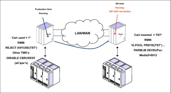
Figure 10-25 Insertion considerations in a DR test
After these settings are done, insert the new TST* logical volumes. It is important that the test volumes inserted using the MI are associated with the test system so that the TS7700 Virtualization Engine at the test site has ownership of the inserted volumes. The DR system must be running before the insertion will be run.
|
Important: Ensure that one logical unit has been or is online on the test system before entering logical volumes.
|
Any new allocations that are performed by the DR test system use only the logical volumes defined for the test. At the end of the test, the volumes can be returned to SCRATCH status and left in the library, or deleted, if you want.
Create data during the DR test from the DR host - Selective Write Protect
During the DR test, you might want to write data from the DR host to the DR clusters. These tests typically include running a batch job cycle that creates new data volumes. This test can be handled in two ways:
•Have a different TS7700 Virtualization Engine available as the output target for the test jobs.
•Have a separate logical volume range that is defined for use only by the test system.
The second approach is the most practical in terms of cost. It involves defining the VOLSER range to be used, defining a separate set of categories for scratch volumes in the DFSMS DEVSUP parmlib, and inserting the volume range into the test TS7700 Virtualization Engine before the start of the test.
|
Important: The test volumes inserted using the MI must be associated with the cluster used as DR cluster so that the TS7700 Virtualization Engine at the test site has ownership of the inserted volumes.
|
If you require that the test host be able to write new data, you can use the Selective Write Protect for DR testing function that allows you to write to selective volumes during DR testing.
With Selective Write Protect, you can define a set of volume categories on the TS7700 that are excluded from the Write Protect Mode. This configuration enables the test host to write data onto a separate set of logical volumes without jeopardizing normal production data, which remains write-protected. This requires that the test host use a separate scratch category or categories from the production environment. If test volumes also must be updated, the test host’s private category must also be different from the production environment to separate the two environments.
You must determine the production categories that are being used and then define separate, not yet used categories on the test host using the DEVSUPxx member. Be sure that you define a minimum of four categories in the DEVSUPxx member: MEDIA1, MEDIA2, ERROR, and PRIVATE.
In addition to the host specification, you must also define on the TS7700 those volume categories that you are planning to use on the DR host and that need to be excluded from Write-Protect mode.
For more information about the necessary definitions for DR testing with a TS7700 grid using Selective Write Protect, see 10.11.1, “TS7700 two-cluster grid using Selective Write Protect” on page 761.
The Selective Write Protect function enables you to read production volumes and to write new volumes from the beginning of tape (BOT) while protecting production volumes from being modified by the DR host. Therefore, you cannot modify or append to volumes in the production hosts’ PRIVATE categories, and DISP=MOD or DISP=OLD processing of those volumes is not possible.
At the end of the DR test, clean up the data written during the DR test.
Create data during the DR test from the DR host - Copy policies
If you are using the management classes used in production, the data being created as part of the test might be copied to the production site, wasting space and inter-site bandwidth. This situation can be avoided by defining the copy mode for the Management Classes differently at the test TS7700 Virtualization Engine than at the production TS7700 Virtualization Engine. Using a copy mode of No Copy for the production library site prevents the test TS7700 Virtualization Engine from making a copy of the test data. It does not interfere with the copying of production data.
Remember to set the content of the management classes back to the original contents in the clean up of the DR test.
Scratch runs during the DR test from the production host
The scratch runs on the production host set the status of a logical volume to scratch. If a logical volume is in a scratch category, it cannot be read from a host.
With TS7700 using Selective Write Protect, you can use the write protect definition “Ignore Fast Ready characteristics if write protected” categories to avoid conflicts. Also, see step 6 on page 763. This approach allows the DR host to only read scratched volumes. It does not prevent the production host from using them. Either turning off return-to-scratch or configuring a long expire-hold time can be used, as well.
For scratch runs during the DR test from the production host without using Selective Write Protect, see 10.9.3, “Considerations for DR tests without Selective Write Protect mode” on page 744.
Scratch runs during the DR test from the DR host
Depending on the selected method, a scratch run on the DR host can be run or not. If Write Protect is enabled, and the production category is not set to Write Protect Excluded, you can process a scratch run on the DR host. Generally, limit the scratch run to the volume serial range allowed for the DR host.
If you choose not to use Write Protect, or define the production categories as excluded from write protect, then a scratch run on the DR host might lead to data loss. Avoid running any housekeeping process.
Clean up phase of a DR test
You need to clean up your DR test environment at the end of the DR test. In this phase, the data written by the DR host are deleted in the TS7700 Virtualization Engine.
If this data is not deleted (set to scratch and run housekeeping) after the DR test, these unneeded data will consume cache or tape space. These data will never expire because no scratch run will be processed for this volume. Ensure that a scratch category with Expiration time is used for the DR logical volumes. Otherwise, they also waste space because these logical volumes will not be overwritten.
10.9.2 Breaking the interconnects between the TS7700 Virtualization Engines
Before R3.1 Flash Copy for DR testing, you had two options:
•The site-to-site links are broken.
•The links are left connected.
A test (with or without Write Protect Mode) can be conducted with either approach, but each one has trade-offs.
Breaking the grid links offers the following benefits:
•You are sure that only the data that has been copied to the TS7700 Virtualization Engine connected to the test system is being accessed.
•Logical volumes that are returned to scratch by the production system are not “seen” by the TS7700 Virtualization Engine under test.
•Test data that is created during the test is not copied to the other TS7700 Virtualization Engine.
This approach has the following disadvantages:
•If a disaster occurs while the test is in progress, data that was created by the production site after the links were broken is lost.
•The TS7700 Virtualization Engine at the test site must be allowed to take over volume ownership (either read-only or read/write).
•The TS7700 Virtualization Engine under test can select a volume for scratch that has already been used by the production system while the links were broken (only if no different media category was used).
•Breaking the gridlinks must be run from the CE. Do not disable a grid link with the Library Request command. Disabling the gridlink with the command does not stop synchronous mode copies and the exchange of status information.
The concern about losing data in a disaster during a test is the major issue with using the “break site-to-site links” method. The TS7700 Virtualization Engine has several design features that make valid testing possible without having to break the site-to-site links.
Ownership takeover
If you perform the test with the links broken between sites, you must enable Read Ownership Takeover so that the test site can access the data on the production volumes owned by the production site. Because the production volumes are created by mounting them on the production site’s TS7700 Virtualization Engine, that TS7700 Virtualization Engine has volume ownership.
If you attempt to mount one of those volumes from the test system without ownership takeover enabled, the mount fails because the test site’s TS7700 Virtualization Engine is not able to request ownership transfer from the production site’s TS7700 Virtualization Engine. By enabling Read Ownership Takeover, the test host is able to mount the production logical volumes and read their contents.
The test host is not able to modify the production site-owned volumes or change their attributes. The volume looks to the test host as a write-protected volume. Because the volumes that are going to be used by the test system for writing data were inserted through the MI that is associated with the TS7700 Virtualization Engine at the test site, that TS7700 Virtualization Engine already has ownership of those volumes. Also, the test host will have complete read and write control of them.
|
Important: Never enable Write Ownership Takeover mode for a test. Write Ownership Takeover mode must be enabled only during a loss or failure of the production TS7700 Virtualization Engine.
|
If you are not going to break the links between the sites, normal ownership transfer occurs whenever the test system requests a mount of a production volume.
10.9.3 Considerations for DR tests without Selective Write Protect mode
As an alternative to the Write Protect Mode with or without Flash Copy if you are at a lower TS7700 microcode level and want to prevent overwriting production data, you can use the tape management system control to allow only read-access to the volumes in the production VOLSER ranges. However, the following process does not allow you to write data during the disaster recovery testing.
For example, with DFSMSrmm, you insert these extra statements into the EDGRMMxx parmlib member:
•For production volumes in a range of A00000 - A09999, add this statement:
REJECT OUTPUT(A0*)
•For production volumes in a range of ABC000 - ABC999, add this statement:
REJECT OUTPUT(ABC*)
With REJECT OUTPUT in effect, products and applications that append data to an existing tape with DISP=MOD must be handled manually to function correctly. If the product is DFSMShsm, tapes that are filling (seen as not full) from the test system control data set must be modified to full by running commands. If DFSMShsm then later needs to write data to tape, it requires a scratch volume related to the test system’s logical volume range.
As a result of recent changes in DFSMSrmm, it now is easier to manage this situation:
•In z/OS V1R10, the new commands PRTITION and OPENRULE provide for flexible and simple control of mixed system environments as an alternative to the REJECT examples used here. These new commands are used in the EDGRMMxx member of parmlib.
•In z/OS V1R9, you can specify extra EXPROC controls in the EDGHSKP SYSIN file to limit the return-to-scratch processing to specific subsets of volumes. So, you can just EXPROC the DR system volumes on the DR system and the PROD volumes on the PROD system. You can still continue to run regular batch processing and also run expiration on the DR system.
Figure 10-26 helps you understand how you can protect your tapes in a DR test while your production system continues running.
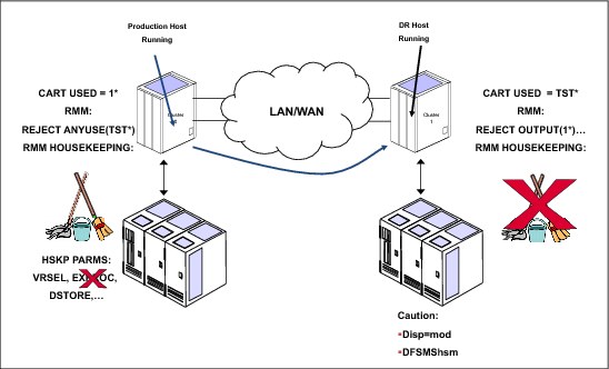
Figure 10-26 Work process in a DR test
|
Clarification: The term “HSKP” is used because this term is typically the job name used to run the RMM EDGHSKP utility that is used for daily tasks, such as vital records processing, expiration processing, and backup of control and journal data sets. However, it can also see the daily process that must be done with other tape management systems. This publication uses the term HSKP to mean the daily process on RMM or any other tape management systems.
|
This includes stopping any automatic short-on-scratch process, if enabled. For example, RMM has one emergency short-on-scratch procedure.
To illustrate the implications of running the HSKP task in a DR test system, see the example in Table 10-2, which displays the status and definitions of one cartridge in a normal situation.
Table 10-2 VOLSER AAAAAA before returned to scratch from the DR site
|
Environment
|
DEVSUP
|
TCDB
|
RMM
|
MI
|
VOLSER
|
|
PROD
|
0002
|
Private
|
Master
|
000F
|
AAAAAA
|
|
DR
|
0012
|
Private
|
Master
|
000F
|
AAAAAA
|
In this example, cartridge AAAAAA is the master in both environments, and if there are any errors or mistakes, it is returned to scratch by the DR system. You can see its status in Table 10-3.
Table 10-3 VOLSER AAAAAA after returned to scratch from the DR site
|
Environment
|
DEVSUP
|
TCDB
|
RMM
|
MI
|
VOLSER
|
|
PROD
|
0002
|
Private
|
Master
|
0012
|
AAAAAA
|
|
DR
|
0012
|
Scratch
|
Scratch
|
0012
|
AAAAAA
|
Cart AAAAAA is now in scratch category 0012, which presents two issues:
•If you need to access this volume from the Prod system, you need to change its status to master (000F) in the MI before you can access it. Otherwise, you lose the data on the cartridge, which can have serious consequences if you, for example, return to scratch 1,000 volumes.
•Using DR RMM, reject using the Prod cartridges to output activities. If this cartridge is mounted in response to a scratch mount, it is rejected by RMM. Imagine that you must mount 1,000 scratch volumes because RMM rejected all of them before you get one validated by RMM.
Perform these tasks to protect production volumes from unwanted return to scratch:
•Ensure that the RMM HSKP procedure is not running during the test window of the test system. There is a real risk of data loss if the test system returns production volumes to scratch and you have defined in TS7700 Virtualization Engine that the expiration time for virtual volumes is 24 hours. After this time, volumes can become unrecoverable.
•Ensure that the RMM short-on-scratch procedure does not start. The results can be the same as running an HSKP.
If you are going to perform the test with the site-to-site links broken, you can use the Read Ownership Takeover mode to prevent the test system from modifying the production site’s volumes. For more information about ownership takeover, see 2.3.33, “Autonomic Ownership Takeover Manager” on page 78.
In addition to the protection options that are described, you can also use the following RACF commands to protect the production volumes:
RDEFINE TAPEVOL x* UACC(READ) OWNER(SYS1)
SETR GENERIC(TAPEVOL) REFRESH
In the command, x is the first character of the VOLSER of the volumes to protect.
Return to scratch without using Selective Write Protect
In a test environment where the links are maintained, care must be taken to ensure that logical volumes that are to be in the test are not returned to SCRATCH status and used by production applications to write new data. There are several ways to prevent conflicts between the return-to-scratch processing and the test use of older volumes:
1. Suspend all return-to-scratch processing at the production site. Unless the test is fairly short (hours, not days), this is not likely to be acceptable because of the risk of running out of scratch volumes, especially for native tape workloads. If all tape processing uses logical volumes, the risk of running out of scratch volumes can be eliminated by making sure that the number of scratch volumes available to the production system is enough to cover the duration of the test.
In z/OS V1R9 and later, you can specify more EXPROC controls in the EDGHSKP SYSIN file to limit the return-to-scratch processing to specific subsets of volumes. So, you can just EXPROC the DR system volumes on the DR system and the PROD volumes on the PROD system. Therefore, you can still continue to run regular batch processing and also run expiration on the DR system.
If a volume is returned to a scratch (Fast Ready) category during a DR test, mounting that volume through a specific mount will not recall the previously written data. Even though DR knows that it is private (remember that TCDB and RMM are a snapshot of production data). TS7700 Virtualization Engine always mounts a blank volume from a scratch (Fast Ready) category. It can be recovered by assigning the volume back to a private (non-Fast Ready) category, or taking that category out of the scratch (Fast Ready) list and trying the mount again.
Even if the number of volumes in the list is larger than the number of volumes needed per day times the number of days of the test, you still need to take steps to make it unlikely that a volume needed for test is reused by production.
For more information, see the “IBM Virtualization Engine TS7700 Series Best Practices - Return-to-Scratch Considerations for Disaster Recovery Testing with a TS7700 Grid” white paper at the following URL:
2. Suspend only the return-to-scratch processing for the production volume needed for the test. For RMM, this can be done by using policy management through vital record specifications (VRSs). A volume VRS can be set up that covers each production volume so that this overrides any existing policies for data sets. For example, the production logical volumes to be used in the test are in a VOLSER range of 990000 - 990999. To prevent them from being returned to scratch, the following subcommand is run on the production system:
RMM AS VOLUME(990*) COUNT(99999) OWNER(VTSTEST) LOCATION(CURRENT) PRIORITY(1)
Then, EDGHSKP EXPROC can be run and not expire the data required for test.
After the test is finished, you have a set of tapes in the TS7700 Virtualization Engine that belong to test activities. You need to decide what to do with these tapes. As a test ends, the RMM database and VOLCAT will probably be destaged (with all the data used in the test), but in the MI database, the tapes remain defined: One will be in master status and the others in SCRATCH status.
If the tapes are not needed anymore, manually release the volumes and then run EXPROC to return the volumes to scratch under RMM control. If the tapes will be used for future test activities, just manually release these volumes. The cartridges remain in the SCRATCH status and ready for use. Remember to use a Scratch category with expiration time to ensure that no space is wasted.
|
Important: Although cartridges in the MI remain ready to use, you must ensure that the next time that you create the test environment that these cartridges are defined to RMM and VOLCAT. Otherwise, you will not be able to use them.
|
When enabled, the new function allows the handling of two instances on the same cluster. The DR host accesses the content of a logical volume from a “point zero”, while the logical volume can be updated with new copies pulled from the production cluster. You do not need a break of the gridlink to ensure that only data from time zero is available to the DR host.
For a detailed technical description, see IBM Virtualization Engine TS7700 Series Best Practices - Flash Copy for Disaster Recovery Testing, which is available at the Techdocs website (search for the term “TS7700”):
The following terms are newly introduced:
•Live Copy: A real-time instance of a virtual tape within a Grid that can be modified and replicated to peer clusters. This is the live instance of a volume in a cluster that is the latest version of the volume on that cluster. If the Live Copy is also consistent relative to the grid, it can be altered by a production host or from a DR host when it is in the exclusion list of write protect.
•Flash Copy: A snapshot of a live copy at time zero. The content in the flash copy is fixed and does not change even if the original copy is modified or if replication events occur. A flash copy might not exist at a particular cluster if a live volume was not present within that cluster at time zero. In addition, a flash copy does not imply consistency because the live copy might have been down level to the grid or simply incomplete at time zero.
•DR Family: A set of TS7700 clusters (most likely those at the DR site) that serve the purpose of disaster recovery. One to seven clusters can be assigned to a DR family. The DR family is used to determine which clusters should be affected by a flash request or write-protect request by using a host console request command (HCR). A DR Family of one TS7720 cluster is supported.
•Write Protect Mode (existing function): When Write Protect Mode is enabled on a cluster, host commands fail if they are sent to logical devices in that cluster and attempt to modify a volume's data or attributes and that volume is not excluded from write protect. The flash copy is created on a cluster when it is in the write protect mode only. Also, only write protected virtual tapes are flashed. Virtual tapes that are assigned to the excluded categories are not flashed.
•Time Zero: The time when the flash copy is taken within a DR family. The time zero mimics the time when a real disaster happens. Customers can establish the time zero using a host console request command.
Basic requirements and concepts
All clusters in the grid must be running with R3.1 or higher microcode level to enable this function.
The Flash Copy for DR testing function is supported on TS7700 Grid configurations where at least one TS7720 cluster exists within the DR location. The function cannot be supported under TS7740-only grids or where a TS7740 is the only applicable DR cluster. A TS7740 might be present and used as part of the DR test so long as at least one TS7720 is also present in the DR site.
The Write Protect exclusion categories are not a subject for the Flash. For these categories only, a Live Copy exists.
During an enabled Flash, the autoremoval process is disabled for the TS7720 member of the DR Family. A TS7720 within a DR location requires extra capacity to accommodate the reuse of volumes and any DR test data that are created within an excluded category. Volumes that are not modified during the test require no additional TS7720 disk cache capacity. The extra capacity requirement must be considered when planning the size of the TS7720 disk cache.
If you are using Time Delay Replication Policy, also check the cache usage of the remaining production cluster TS7720. Remember that volumes can be removed from the TS7720 only when the “T” copies are processed (either in the complete grid, or in the family).
DR Family
In R3.1, one DR Family can be defined. A DR Family can be defined, modified, and deleted with the Library Request command. After a flash is enabled, a DR Family cannot be modified.
At least one TS7720 must be part of the DR Family. You can optionally include one or more TS7740s. The TS7740 does not have the same functionality in a DR Family that the TS7720 has. The Write Protect excluded media categories needs to be consistent on all clusters in a DR Family. If not consistent, the flash copy will not be enabled.
Restrictions
DR tests have the following restrictions:
•There is no autoremoval of data from a TS7720 if the Flash is enabled.
•Do not perform the DR testing using the Flash Copy function when a cluster in the grid is unavailable. An attempt to enable a flash copy in this situation results in a failure. You can perform the DR testing using the Flash Copy function if all clusters in the grid are powered on (they can be in service/offline state).
•To perform the Flash Copy function, all clusters in a grid must be reachable via the grid links. Otherwise, host console commands to enable write protect mode/flash copy fail with an internal error.
Write Protect and Flash Copy enablement / disablement
The Flash Copy is based on a Write Protect Mode. You can enable the Write Protect Mode first and the Flash Copy later, or you can enable them together.
If you want to disable the Flash Copy, you need first to disable the Flash Copy and later on the Write Protect Mode. Also, you can run the action with a single command.
|
Note: A Flash Copy cannot be enabled if Write Protect Mode was enabled from the MI.
|
Do not enable the Flash Copy if production hosts with Tape processing have device allocations on the clusters where the Flash will be enabled. Failures might occur because the Read only mode does not allow subsequent mounts.
Livecopy enablement on a TS7740 in a DR Family
A DR Family must contain at least one TS7720. TS7740 can be defined optionally to a DR Family.
The TS7740 itself has no flash. To ensure that during a DR test only data from Time Zero are used, all mounts need to be run on the TS7720. The TS7720 uses the data in its own cache first. If no valid copy exists, the TS7720 identifies if the TS7740 has a copy before Time Zero. If no valid copy from time zero exists, the host mount fails.
A remote mount from the TS7740 can occur if the livecopy parameter is enabled. To enable the livecopy option, run this command:
LI REQ, <clib_name>, DRSETUP, <family_name>, LIVECOPY, NONE
To disable the livecopy option, run this command:
LI REQ, <clib_name>, DRSETUP, <family_name>, LIVECOPY, FAMILY
The livecopy setting is persistent. Disabling the Flash Copy will not change the setting. Only a complete deletion of the DR Family can change the setting.
|
Important: Use the TS7740 in a DR Family only for remote mounts. Do not vary online the TS7740 devices directly to the DR host.
|
10.10 Disaster recovery testing detailed procedures for Flash Copy
Detailed instructions are provided that include all the necessary steps to perform a DR test, such as pre-test task, post-test task, production host task, recovery site
For a detailed description of all commands, see IBM Virtualization Engine TS7700 Series Best Practices - Flash Copy for Disaster Recovery Testing, which is available at the Techdocs website (search for the term “TS7700”):
10.10.1 Plan your DR test
Complete these steps to properly plan your DR test:
1. Ensure, that the TS7720s in the DR Family has sufficient space to hold the Flash data. Remember, that the Autoremoval function is not available while the Flash is enabled. Do a temporary autoremoval process in advance if necessary.
2. Define the DR Family name and which cluster will be members of the DR Family
3. If a TS7740 is part of the DR Family, define whether Livecopy should be used
4. Define the Write Protect exclude media categories for the DR host
5. Define the parameters of the scratch category (Expiration time)
6. Define the logical volume serial range used by the DR host
7. Define the number of scratch volumes needed in the DR host
8. Define the cleanup phase (scratch of the DR volume serial range)
9. Plan cache usage from TS7720 DR clusters and TS7720 production clusters during the DR test timeline
10.10.2 Run Phase 1 Preparation
In this phase, all necessary definitions and actions before the actual enabling of the Flash are processed. The actual shutdown or restart of your DR host is not included because that depends on your situation.
1. Define the DEVSUPxx member in the DR host, and ensure that the new categories are used. Use either the DS QL,CATS command, or process an IPL. If you choose to switch categories with the command, ensure that before the switch no tape processing occurs.
2. Change the Tape Management System to allow the new volume serial ranges for output processing.
3. Insert the new volume serial ranges on the MI. Remember to have at least one device online to the DR host.
4. Define the Write Protect excluded media categories on all clusters (using the MI) belonging to the DR Family. Remember, you need MEDIA1, MEDIA2, and the PRIVATE categories.
5. Change the Expiration time on the scratch category for MEDIA1 and MEDIA2 if necessary
6. Offline all TS7740 devices to the DR host
7. Modify the Automatic Allocation Managers device tables (if necessary)
8. Change the Autoremoval Temporary Threshold on the TS7720 used for DR testing to ensure that enough cache space is available for DR data and production data. Remember, no auto removal can occur on the DR host during the DR test. Wait until the Temporary auto removal process completes.
9. If applicable, change the Autoremoval Temporary Threshold on the remaining production TS7720 and wait until the removal processing completes.
10.10.3 Run Phase 2 Enablement
Now, the DR Family is defined, and the Write Protect and Flash Copy is enabled in one step. Also, allow the usage of the Livecopy in a TS7740 (because a TS7740 is a family member).
1. Create a DR Family or add a cluster (remember to add the TS7720 first). See Example 10-9.
LI REQ, <COMPOSITE>,DRSETUP, <FAMILYNAME>, ADD, <CLUSTER ID>
Example 10-9 Create a DR Family and add a cluster
-LI REQ,HYDRAG,DRSETUP,DRFAM01,add,2
CBR1020I Processing LIBRARY command: REQ,HYDRAG,DRSETUP,DRFAM01,ADD,1.
CBR1280I Library HYDRAG request. 939
Keywords: DRSETUP,DRFAM01,ADD,1
----------------------------------------------------------------------
DRSETUP V1 .0
DR FAMILY DRFAM01 WAS NEWLY CREATED
CLUSTER 1 WAS ADDED TO DR FAMILY DRFAM01 SUCCESSFULLY
2. Add a TS7740 to the DR Family (only if required). See Example 10-10.
LI REQ, <COMPOSITE>,DRSETUP, <FAMILYNAME>, ADD, <CLUSTER ID>
Example 10-10 Add a TS7740 to the DR Family
LI REQ,HYDRAG,DRSETUP,DRFAM01,add,2
CBR1020I Processing LIBRARY command: REQ,HYDRAG,DRSETUP,DRFAM01,ADD,2.
CBR1280I Library HYDRAG request. 946
Keywords: DRSETUP,DRFAM01,ADD,2
----------------------------------------------------------------------
DRSETUP V1 .0
i. CLUSTER 2 WAS ADDED TO DR FAMILY DRFAM01 SUCCESSFULLY
3. Define the Livecopy Usage (if needed). See Example 10-11.
LI REQ, <COMPOSITE>,DRSETUP, <FAMILYNAME>, LIVECOPY,FAMILY
Example 10-11 Define the Livecopy Usage
LI REQ,HYDRAG,DRSETUP,SHOW,DRFAM01
CBR1020I Processing LIBRARY command: REQ,HYDRAG,DRSETUP,SHOW,DRFAM01.
CBR1280I Library HYDRAG request. 230
Keywords: DRSETUP,DRFAM01,LIVECOPY,FAMILY
---------------------------------------------------------
DRSETUP V1 .0
LIVE COPY USAGE HAS BEEN UPDATED TO FAMILY SUCCESSFULLY
4. Check the DR Family settings (Example 10-12).
LI REQ, <COMPOSITE>,DRSETUP, SHOW, <FAMILYNAME>
Example 10-12 Check the DR Family Settings
LI REQ,HYDRAG,DRSETUP,SHOW,DRFAM01
CBR1020I Processing LIBRARY command: REQ,HYDRAG,DRSETUP,SHOW,DRFAM01.
CBR1280I Library HYDRAG request. 302
Keywords: DRSETUP,SHOW,DRFAM01
----------------------------------------------------------------------
DRSETUP V1 .0
DR FAMILY VIEW
ID FAM NAME FLASH FLASH TIME (UTC) LCOPY MEMBER CLUSTERS
1 DRFAM01 INACTIVE N/A FAMILY - 1 2 - - - - -
----------------------------------------------------------------------
FAMILY MEMBER WRITE PROTECT STATUS VIEW
CLUSTER WRT-PROTECT EXCATS-NUM IGNORE-FR ENABLED-BY
CLUSTER1 DISABLED 3 TRUE N/A
CLUSTER2 DISABLED 3 TRUE N/A
----------------------------------------------------------------------
CATEGORIES EXCLUDED FROM WRITE PROTECTION WITHIN DR FAMILY DRFAM01
CLUSTER ACTIVE EXCLUDED CATEGORIES
CLUSTER1 0092 009F 3002
CLUSTER1 0092 009F 3002
5. Enable the Flash Copy. Refer to Example 10-13
LI REQ, <COMPOSITE>,DRSETUP, <FAMILYNAME>, DOALL,ENABLE
Example 10-13 Enable the Flash Copy
LI REQ,HYDRAG,DRSETUP,DRFAM01,DOALL,ENABLE
CBR1020I Processing LIBRARY command: REQ,HYDRAG,DRSETUP,DRFAM01,DOALL
ENABLE.
CBR1280I Library HYDRAG request. 154
Keywords: DRSETUP,DRFAM01,DOALL,ENABLE
---------------------------------------------------------------------
DRSETUP V1 .0
WRITE PROTECT STATUS HAS BEEN ENABLED SUCCESSFULLY
FLASH COPY HAS BEEN CREATED SUCCESSFULLY 
6. Check the DR Family settings again. Refer to Example 10-14.
LI REQ, <COMPOSITE>,DRSETUP, SHOW, <FAMILYNAME>
Example 10-14 Check the DR Family Settings 
LI REQ,HYDRAG,DRSETUP,SHOW,DRFAM01
CBR1020I Processing LIBRARY command: REQ,HYDRAG,DRSETUP,SHOW,DRFAM01.
CBR1280I Library HYDRAG request. 758
Keywords: DRSETUP,SHOW,DRFAM01
---------------------------------------------------------------------
DRSETUP V1 .0
DR FAMILY VIEW
ID FAM NAME FLASH FLASH TIME (UTC) LCOPY MEMBER CLUSTER
1 DRFAM01 ACTIVE 2014-02-24-14.03.35 FAMILY - 1 2 - - - -
---------------------------------------------------------------------
FAMILY MEMBER WRITE PROTECT STATUS VIEW
CLUSTER WRT-PROTECT EXCATS-NUM IGNORE-FR ENABLED-BY
CLUSTER1 ENABLED 3 TRUE LIREQ
CLUSTER2 ENABLED 3 TRUE LIREQ
---------------------------------------------------------------------
CATEGORIES EXCLUDED FROM WRITE PROTECTION WITHIN DR FAMILY DRFAM01
CLUSTER ACTIVE EXCLUDED CATEGORIES
CLUSTER1 0092 009F 3002
CLUSTER2 0092 009F 3002
10.10.4 Run Phase 3 Run DR test
During the DR test, you might want to check the status of these logical volumes:
•Newly produced volumes from production
•Updated volumes from production
•Newly produced volumes from DR
You can use the following commands to identify if a flash copy exists for a specific volume, and the status from the livecopy and the flashcopy.
To do so, use the D SMS,VOL(xxxxxx) and the D SMS,VOL(xxxxxx),FLASH commands.
As long the livecopy volume is identically with the flash copy volume, the status will be “ACTIVE”. Only if the logical volume was updated from production, and a second instance exists, the status changes to “CREATED” (Example 10-15).
Example 10-15 Display of a logical volume after modification from production - Livecopy
LI REQ,HYDRAG,LVOL,A08760
CBR1020I Processing LIBRARY command: REQ,HYDRAG,LVOL,A08760.
CBR1280I Library HYDRAG request. 883
Keywords: LVOL,A08760
-------------------------------------------------------------
LOGICAL VOLUME INFORMATION V3 .0
LOGICAL VOLUME: A08760
MEDIA TYPE: ECST
COMPRESSED SIZE (MB): 2763
MAXIMUM VOLUME CAPACITY (MB): 4000
CURRENT OWNER: cluster1
MOUNTED LIBRARY:
MOUNTED VNODE:
MOUNTED DEVICE:
TVC LIBRARY: cluster1
MOUNT STATE:
CACHE PREFERENCE: PG1
CATEGORY: 000F
LAST MOUNTED (UTC): 2014-03-11 10:19:47
LAST MODIFIED (UTC): 2014-03-11 10:18:08
LAST MODIFIED VNODE: 00
LAST MODIFIED DEVICE: 00
TOTAL REQUIRED COPIES: 2
KNOWN CONSISTENT COPIES: 2
KNOWN REMOVED COPIES: 0
IMMEDIATE-DEFERRED: N
DELETE EXPIRED: N
RECONCILIATION REQUIRED: N
LWORM VOLUME: N
FLASH COPY: CREATED
----------------------------------------------------------------
LIBRARY RQ CACHE PRI PVOL SEC PVOL COPY ST COPY Q COPY CP
cluster1 N Y ------ ------ CMPT - RUN
cluster2 N Y ------ ------ CMPT - RUN
Example 10-16 shows the flash instance of the same logical volume.
Example 10-16 Display of a logical volume after modification from production - Flash volume
LI REQ,HYDRAG,LVOL,A08760,FLASH
CBR1020I Processing LIBRARY command: REQ,HYDRAG,LVOL,A08760,FLASH
CBR1280I Library HYDRAG request. 886
Keywords: LVOL,A08760,FLASH
-----------------------------------------------------------------
LOGICAL VOLUME INFORMATION V3 .0
FLASH COPY VOLUME: A08760
MEDIA TYPE: ECST
COMPRESSED SIZE (MB): 0
MAXIMUM VOLUME CAPACITY (MB): 4000
CURRENT OWNER: cluster2
MOUNTED LIBRARY:
MOUNTED VNODE:
MOUNTED DEVICE:
TVC LIBRARY: cluster1
MOUNT STATE:
CACHE PREFERENCE: ---
CATEGORY: 000F
LAST MOUNTED (UTC): 1970-01-01 00:00:00
LAST MODIFIED (UTC): 2014-03-11 09:05:30
LAST MODIFIED VNODE:
LAST MODIFIED DEVICE:
TOTAL REQUIRED COPIES: -
KNOWN CONSISTENT COPIES: -
KNOWN REMOVED COPIES: -
IMMEDIATE-DEFERRED: -
DELETE EXPIRED: N
RECONCILIATION REQUIRED: N
LWORM VOLUME: -
---------------------------------------------------------------
LIBRARY RQ CACHE PRI PVOL SEC PVOL COPY ST COPY Q COPY CP
cluster2 N Y ------ ------ CMPT - RUN
Only the clusters from the DR Family (in this case only a TS7720 was defined in the DR Family) are shown. This information is also available on the MI.
In Example 10-17 on page 756, you see a copy with an active, created flash copy. That means that the logical volume is not only in a write protected category and therefore part of the flash, but also that the logical volume was updated during the DR test. Therefore, the Flash instance was created. The detail for last access by a host is the information from the livecopy (even on the DR Cluster). To see the information from the created flash copy instance, select the FLASH COPY “CREATED” field. This opens a second view as shown in Figure 10-27.
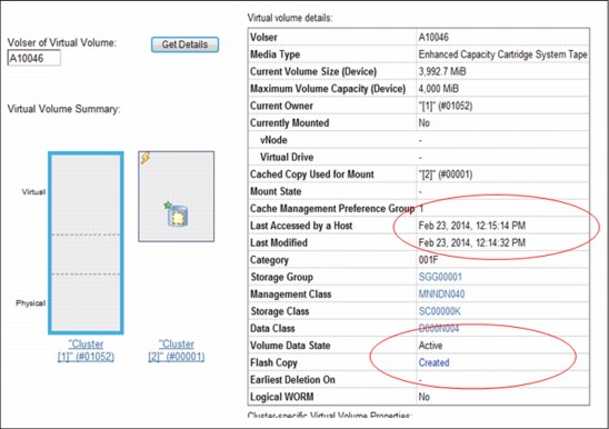
Figure 10-27 Display of a logical volume with an active Flash copy
Figure 10-28 shows the next view, which is opened by clicking Created.

Figure 10-28 Display of the Flash Copy information of a logical volume
Run your DR test. During the execution, monitor the cache usage of your TS7720 clusters. For the TS7720 cluster used as DR, you have two new possibilities.
The following HCR command provides you the information of the space used by the Flash copy on the bottom of the output. See Example 10-17.
LI REQ,distributed library name,CACHE
Example 10-17 Cache Consumption Flash Copy
LI REQ,distributed library name,CACHE
CBR1280I Library VTSDIST1 request.
Keywords: CACHE
----------------------------------------------------------------------
TAPE VOLUME CACHE STATE V3 .0
PRIMARY TAPE MANAGED PARTITIONS
INSTALLED/ENABLED GBS 0/ 0
CACHE ENCRYPTION STATUS:
PARTITION ALLOC USED PG0 PG1 PMIGR COPY PMT CPYT
0 0 0 0 0 0 0 0 0
1 0 0 0 0 0 0 0 0
2 0 0 0 0 0 0 0 0
3 0 0 0 0 0 0 0 0
4 0 0 0 0 0 0 0 0
5 0 0 0 0 0 0 0 0
6 0 0 0 0 0 0 0 0
7 0 0 0 0 0 0 0 0
PRIMARY CACHE RESIDENT ONLY INFORMATION
INSTALLED/ENABLED GBS 95834/ 95834
ADJUSTED CACHE USAGE 5172
CACHE ENCRYPTION STATUS: CAPABLE
ALLOCATED USED PIN PKP PRM COPY CPYT
95834 5151 0 5150 0 0 0
FLASH COPY INFORMATION
INDEX ENABLED SIZE
1 YES 252
2 NO 0
3 NO 0
4 NO 0
5 NO 0
6 NO 0
7 NO 0
8 NO 0
You can find the same information also on the MI. You can select the following display windows:
•Monitor
•Performance
•Cache Usage
Figure 10-29 is an example of cache utilization output.

Figure 10-29 Cache usage of Flash Copy Data
Also, you can control the usage of your virtual drives. You can select these displays on the MI:
•Virtual
•Virtual Tape Drives
Figure 10-30 is an example of virtual tape drive output.
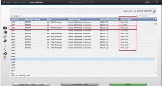
Figure 10-30 Virtual Tape Drive panel during a Flash Copy for DR test
10.10.5 Run Phase 4 Clean Up
Before you end the DR test, clean up the environment. Depending on your DR test strategy, this might include these steps:
1. Scratch all used logical volumes from the DR host during the DR test.
2. Run a housekeeping job on the DR host that includes only the logical volume serial ranges used by the DR host
3. Stop the DR host processing
All data created on the DR host will be scratch after this process. Depending on the definition of the Scratch Media Category, these data are expired soon. That ensures that these data do not use any cache in the TS7700 clusters.
It is mandatory to run these processes before you disable the Write Protect/Flash Copy.
10.10.6 Run Phase 5 Disable of the Write Protect and Flash Copy
After the cleanup, you can disable the Write Protect and delete the Flash copy. Example 10-18 shows the disable and delete in one step.
Example 10-18 Disable the Write Protect and Flash Copy
LI REQ,HYDRAG,DRSETUP,DRFAM01,DOALL,DISABLE
CBR1020I Processing LIBRARY command: REQ,HYDRAG,DRSETUP,DRFAM01,DOALL
DISABLE.
CBR1280I Library HYDRAG request. 765
Keywords: DRSETUP,DRFAM01,DOALL,DISABLE
---------------------------------------------------------------------
DRSETUP V1 .0
WRITE PROTECT STATUS HAS BEEN DISABLED SUCCESSFULLY
FLASH COPY HAS BEEN DELETED SUCCESSFULLY
You can now switch back to original system setup. That means, you can bring back all devices from all clusters of the DR Family back to production and change your Automation Allocation Manager setup.
10.10.7 Expected Failures during the DR test
The next section covers some expected failures during a DR test.
The messages in Example 10-19 might appear if you try to read a logical volume that was not present at time zero in the DR Family.
Example 10-19 Expected failures during the DR test
IEF233A M 2500,A08759,,DENEKA1,STEP1,DENEKA.HG.TEST1.DUMP1
CBR4195I LACS retry possible for job DENEKA1: 399
IEE763I NAME= CBRLLACS CODE= 140394
CBR4000I LACS WAIT permanent error for drive 2500.
CBR4171I Mount failed. LVOL=A08759, LIB=HYDRAG, PVOL=??????,RSN=22
The message in Example 10-20 might also appear if you want to modify a volume that is in a write protect media category.
Example 10-20 Error message for volume in a write media category
IEF116I DENEKY6 STEP1 - MOUNT OF VOLUME PRIVAT ON DEVICE 2580 FAILED
IEE763I NAME= CBRLLACS CODE= 14017E
CBR4000I LACS MOUNT permanent error for drive 2580.
CBR4126I Library HYDRAG drive is in read only mode.
IEF272I DENEKY6 STEP1 - STEP WAS NOT EXECUTED
The message in Example 10-21 might occur if a job was running on the cluster while the Flash Copy was enabled.
Example 10-21 Message for job running on the cluster while Flash Copy was enabled
IEF233A M 2507,A10088,,DENEKA8,STEP2,DENEKA.HG.TEST1.DUMP1
IEC518I SOFTWARE ERRSTAT: WRITPROT 2507,A10088,SL,DENEKA8,STEP2
IEC502E RK 2507,A10088,SL,DENEKA8,STEP2
IEC147I 613-24,IFG0194F,DENEKA8,STEP2,AUS1,2507,,DENEKA.HG.TEST1.DUMP1
10.11 Disaster recovery testing detailed procedures for alternatives before R3.1
Detailed instructions are provided that include all the necessary steps to run a DR test, such as pre-test task, post-test task, production host task, recovery site task, and so on.
The best DR test is a “pseudo-real” DR test, which means stopping the production site and starting real production at the DR site. However, stopping production is rarely realistic, so the following scenarios assume that production must continue working during the DR test. The negative aspect of this approach is that DR test procedures and real disaster procedures can differ slightly.
|
Tips: In a DR test on a TS7700 grid, without using Selective Write Protect, with production systems running concurrently, be sure that no return-to-scratch or emergency short-on-scratch procedure is started in the test systems. You can return to scratch production tapes, as discussed in “Return to scratch without using Selective Write Protect” on page 746.
In a DR test on a TS7700 grid using Selective Write Protect, with production systems running concurrently, you can use the “Ignore fast ready characteristics of write-protected categories” option together with Selective Write Protect as described in “Create data during the DR test from the DR host - Selective Write Protect” on page 741.
|
Procedures are described for four scenarios, depending on the TS7700 release level, grid configuration, and connection status during the test:
1. TS7700 two-cluster grid using Selective Write Protect
This scenario describes the steps for running a DR test by using the Selective Write Protect DR testing enhancements. Whether the links between the clusters are broken is irrelevant. For more information, see 10.11.1, “TS7700 two-cluster grid using Selective Write Protect” on page 761.
2. TS7700 two-cluster grid without using Selective Write Protect
This scenario assumes that the DR test is run with production running in parallel on a TS7700 two-cluster grid. The links between both clusters are not broken, and you cannot use the Selective Write Protect DR enhancements. For more information, see 10.11.2, “TS7700 two-cluster grid not using Selective Write Protect” on page 767.
3. TS7700 two-cluster grid without using Selective Write Protect
This scenario assumes that the DR test is run on a TS7700 two-cluster grid without using Selective Write Protect with the links broken between both clusters so the production cannot be affected by the DR test. For more information, see 10.11.2, “TS7700 two-cluster grid not using Selective Write Protect” on page 767.
4. TS7700 three-cluster grid without using Selective Write Protect
This scenario is similar to TS7700 two-cluster grid without using Selective Write Protect, but running production in parallel on a three-cluster grid. The links between both clusters are not broken, and you cannot use the Selective Write Protect DR enhancements. See 10.11.3, “TS7700 three-cluster grid not using Selective Write Protect” on page 770.
10.11.1 TS7700 two-cluster grid using Selective Write Protect
Figure 10-31 shows a sample multicluster grid scenario using Selective Write Protect. The left cluster is the Production Cluster, and the right cluster is the DR Cluster.

Figure 10-31 Sample DR testing scenario with TS7700 using Selective Write Protect
|
Clarification: You can also use the steps described in the following procedure when running DR testing on one cluster within a three-cluster or four-cluster grid. To run DR testing on more than one host or cluster, repeat the steps in the procedure on each of the DR hosts and clusters involved in the test.
|
Perform the following steps to prepare your DR environment:
1. Vary all virtual drives of the DR Cluster offline to the normal production hosts and to the DR hosts.
2. Ensure that the production hosts have access to the Production Cluster so that normal tape processing can continue.
3. On the MI, select Configuration → Write Protect Mode.
The window shown in Figure 10-32 opens.

Figure 10-32 TS7700 Write Protect Mode window
4. Click Enable Write Protect Mode to set the cluster in Write Protect Mode.
Be sure to also leave the Ignore fast ready characteristics of write protected categories selected. This setting ensures that volumes in Production scratch (Fast Ready) categories that are write-protected on the DR Cluster are treated differently.
Normally, when a mount occurs to one of these volumes, the TS7700 assumes that the host starts writing at BOT and creates a stub. Also, when “Expire Hold” is enabled, the TS7700 does not allow any host access to these volumes until the hold period passes. Therefore, if the production host returns a volume to scratch “After” time zero, the DR host still believes within its catalog that the volume is private and the host will want to validate its contents. It cannot afford to allow the TS7700 to stub it or block access if the DR host attempts to mount it.
The “Ignore fast ready characteristics of write protected categories” option informs the DR Cluster that it must ignore these characteristics and treat the volume as a private volume. It will then surface the data versus a stub and will not prevent access because of Expire Hold states. However, it will still prevent write operations to these volumes.
Click Submit Changes to activate your selections.
5. Decide which set of categories you want to use during DR testing on the DR hosts and confirm that no host system is using this set of categories, for example X’0030’ - X’003F’.
You define those categories to the DR host in a later step.
On the DR cluster TS7700 MI, define two scratch (Fast Ready) categories as described in “Defining scratch (Fast Ready) categories” on page 492. These two categories are used on the DR host as scratch categories, MEDIA1 and MEDIA2 (X’0031’ and X’0032’), and are defined as excluded from Write-Protect mode.
6. In the DR cluster MI, use the Write Protect Mode window (shown in Figure 10-32 on page 762) to define the entire set of categories to be excluded from Write-Protect Mode, including the Error and the Private categories.
On the bottom of the window, click Select Action → Add, and then, click Go. The next window opens (Figure 10-33).

Figure 10-33 Add Category window
Define the categories that you have decided to use for DR testing, and ensure that “Excluded from Write Protect” is set to Yes. In the example, you define volume categories X’0030’ through X’003F’ or, as a minimum, X’0031’ (MEDIA1), X’0032’ (MEDIA2), X’003E’ (ERROR), and X’003F’ (PRIVATE).
7. On the DR Cluster, ensure that no copy is written to the Production Cluster that defines the Copy Consistency Point of “No Copy” in the Management Class definitions that are used by the DR host.
8. On the DR host, restore your DR system.
9. Change the DEVSUPxx member on the DR host to use the newly defined DR categories. DEVSUPxx controls installation-wide default tape device characteristics, for example:
– MEDIA1 = 0031
– MEDIA2 = 0032
– ERROR = 003E
– PRIVATE = 003F
Therefore, the DR host is enabled to use these categories that have been excluded from Write-Protect Mode in Step 6.
10. On the DR host, define a new VOLSER range to your tape management system.
11. Insert that VOLSER range on the DR Cluster and verify that Volume Insert Processing has assigned them to the correct scratch (Fast Ready) categories.
12. On the DR host, vary online the virtual drives of the DR Cluster. Start DR testing.TS7700 two-cluster grid not using Selective Write Protect
The standard scenario is a DR test in a DR site while real production occurs. In this situation, the grid links are not broken because the production site is working and it needs to continue copying cartridges to the DR site to be ready if a real disaster happens while you are running the test.
The following points are assumed:
•The grid links must not be broken.
•The production site will be running everyday jobs as usual.
•The DR site must not affect the production site in any way.
•The DR site is ready to start if a real disaster happens.
Figure 10-34 shows the environment and the main tasks to perform in this DR situation.
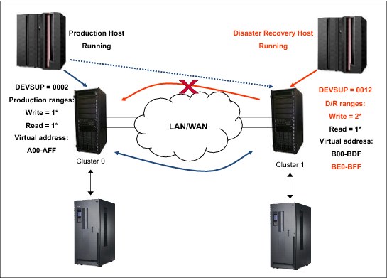
Figure 10-34 Disaster recovery environment: Two clusters and links not broken
Note the following information about Figure 10-34:
•The production site can write and read its usual cartridges (in this case, 1*).
•The production site can write in any address in Cluster 0 or Cluster 1.
•The DR site can read production cartridges (1*), but cannot write on this range. You must create a new range for this purpose (2*) that cannot be accessible by the production site.
•Ensure that no production tapes can be modified in any way by DR site systems.
•Ensure that the production site does not rewrite tapes that are needed during the DR test.
•Do not waste resources copying cartridges from the DR site to the production site.
Issues
Consider the following issues with TS7700 without using Selective Write Protect environments:
•You must not run the HSKP process in the production site unless you can run it without the EXPROC parameter in RMM. In z/OS V1R10, the new RMM parmlib commands PRTITION and OPENRULE provide for flexible and simple control of mixed system environments.
In z/OS V1R9 and later, you can specify extra EXPROC controls in the EDGHSKP SYSIN file to limit the return-to-scratch processing to specific subsets of volumes. Therefore, you can use EXPROC on the DR system volumes on the DR system and use the PROD volumes on the PROD system. You can still continue to run regular batch processing and also run expiration on the DR system.
•With other TMSs, you need to stop the return-to-scratch process, if possible. If not, stop the whole daily process. To avoid problems with scratch shortage, you can add more logical volumes.
•If you run HSKP with the EXPROC (or daily processes in other TMSs) parameter in the production site, you cannot expire volumes that might be needed in the DR test. If you fail to do so, TS7700 Virtualization Engine sees these volumes as scratch. With the scratch (Fast Ready) category on, TS7700 Virtualization Engine presents the volume as a scratch volume, and you lose the data on the cartridge.
•Ensure that HSKP or short-on-scratch procedures are deactivated in the DR site.
Tasks before the DR test
Before running the DR test of the TS7700 Virtualization Engine grid, prepare the environment and complete tasks that allow you to run the test without any problems or without affecting your production systems.
Perform the following steps:
1. Plan and decide the scratch categories that are needed in the DR site (1*). See “Number of scratch volumes needed per day” on page 147.
2. Plan and decide the VOLSER ranges that will be used to write in the DR site (2*).
3. Modify the production site PARMLIB RMM member EDGRMMxx:
a. Include REJECT ANYUSE (2*) to avoid having the production system using or accepting the insertion of 2* cartridges.
b. If your tape management system is not RMM, disable CBRUXENT exit before inserting cartridges in the DR site.
4. Plan and decide the virtual address used in the DR site during the test (BE0-BFF).
5. Insert extra scratch virtual volumes to ensure that during the DR test that production cartridges can return to scratch but are not rewritten afterward. This must be done in the production site. For more information, see “Physical Tape Drives” on page 377.
6. Plan and define a new Management Class with copy policies on No Rewind (NR) using the MI at the DR site, for example, NOCOPY. For more information, see 8.2.7, “The Constructs icon” on page 383.
Tasks during the DR test
After starting the DR system, but before the real DR test can start, you must change several things to be ready to use tapes from the DR site. Usually, the DR system is started by using a “clone” image of the production system, so you need to alter certain values and definitions to customize the image for the DR site.
Follow these necessary steps:
1. Modify DEVSUPxx in SYS1.PARMLIB at the DR site and define the scratch category selected for DR.
2. Use the command DEVSERV QLIB,CATS at the DR site to change scratch categories dynamically. See “DEVSERV QUERY LIBRARY command” on page 532.
3. Modify the test PARMLIB RMM member EDGRMMxx at the DR site:
a. Include REJECT OUTPUT (1*) to allow only read activity against production cartridges.
b. If you have another TMS product, ask your software provider how to use a similar function, if one exists.
4. Modify test PARMLIB RMM member EDGRMMxx at the DR site and delete REJECT ANYUSE(2*) to allow write and insertion activity of 2* cartridges.
5. Define a new SMS MC (NOCOPY) in SMS CDS at the DR site.
6. Modify the MC ACS routine at the DR site. All the writes must be directed to MC NOCOPY.
7. Restart the SMS configuration at the DR site.
8. Insert a new range (2*) of cartridges from the MI at the DR site. Ensure that all the cartridges are inserted in DR TS7700 Virtualization Engine so the owner is the TS7700 Virtualization Engine in DR site:
a. If you have RMM, your cartridges are defined automatically to TCDB and RMM.
b. If you have another TMS, check with the original equipment manufacturer (OEM) software provider. In general, to add cartridges to other TMSs, you need to stop them.
9. Perform the next modification in DFSMShsm at the DR site:
a. Mark all hierarchical storage management (HSM) Migration Level 2 (ML2) cartridges as full by using the DELVOL MARKFULL HSM command.
b. Run HOLD HSM RECYCLE.
10. Again, ensure that the following procedures do not run:
– RMM housekeeping activity at the DR site
– Short-on-scratch RMM procedures at the DR site
Tasks after the DR test
After the test is finished, you will have a set of tapes in the TS7700 Virtualization Engine that are used by the test activities. You need to decide what to do with these tapes. As the test ends, the RMM database and VOLCAT are destaged (because all the data was used in the test), but in the MI database, the tapes remain defined: One will be in master status and the others in SCRATCH status.
What you do with these tapes depends on whether they are no longer needed or if the tapes will be used for future DR test activities.
If the tapes are not needed anymore, complete the following steps:
1. Stop the RMM address space and subsystem, and by using Interactive Storage Management Facility (ISMF) 2.3 (at the DR site), return to scratch all private cartridges.
2. After all of the cartridges are in the SCRATCH status, use ISMF 2.3 again (at the DR site) to eject all the cartridges. Remember that the MI can only accept 1,000 eject commands at one time. If you must eject a higher number of cartridges, the process will be time-consuming.
In the second case (tapes will be used in the future), run only step 1. The cartridges remain in the SCRATCH status and are ready for future use.
|
Important: Although cartridges in the MI remain ready to use, you must ensure that the next time that you create the test environment that these cartridges are defined to RMM and VOLCAT. Otherwise, you will not be able to use them.
|
10.11.2 TS7700 two-cluster grid not using Selective Write Protect
In other situations, you can choose to break grid links, even if your production system is running during a DR test.
Assume that the following information is true:
•The grid links are broken.
•The production site will be running everyday jobs as usual.
•The DR site cannot affect the production site.
•The DR site is ready for a real disaster.
Do not use logical drives in the DR site from the production site.
If you decide to “break” links during your DR test, you must review carefully your everyday work. For example, if you have 3 TB of cache and you write 4 TB of new data every day, you are a good candidate for a large amount of throttling, probably during your batch window. To understand throttling, see 9.3.7, “Throttling in the TS7700” on page 598.
After the test ends, you might have many virtual volumes in pending copy status. When TS7700 Virtualization Engine grid links are restored, communication is restarted, and the first task that the TS7700 Virtualization Engine runs is to make a copy of the volumes created during your “links broken” window. This can affect the TS7700 Virtualization Engine performance.
If your DR test runs over several days, you can minimize the performance degradation by suspending copies by using the GRIDCNTL Host Console command. After your test is over, you can enable the copy again during a low activity workload to avoid or minimize performance degradation. See 8.4.3, “Host Console Request function” on page 534 for more information.
Figure 10-35 shows the environment and the main tasks to perform in this DR scenario.

Figure 10-35 Disaster recovery environment: Two clusters and broken links
Note the following information about Figure 10-35:
•The production site can write and read its usual cartridges (in this case, 1*).
•The production site writes only to virtual addresses associated with Cluster 0. The tapes remain, pending copy.
•The DR site can read production cartridges (1*) but cannot write on this range. You must create a new one for this purpose (2*). This new range must not be accessible by the production site.
•Ensure that no production tapes can be modified by the DR site systems.
•Ensure that the production site does not rewrite tapes that are needed during the DR test.
•Do not waste resources copying cartridges from the DR site to the production site.
Issues
Consider the following items:
•You can run the whole HSKP process at the production site. Because communications are broken, the return-to-scratch process cannot be completed in the DR TS7700 Virtualization Engine, so your production tapes never return to scratch in the DR site.
•In this scenario, be sure that HSKP or short-on-scratch procedures are deactivated in the DR site.
Tasks before the DR test
Before you start the DR test for the TS7700 Virtualization Engine grid, prepare the environment and complete several tasks so that you can run the test without any problems and without affecting your production site.
Perform the following steps:
1. Plan and decide on the scratch categories needed at the DR site (1*). See “Number of scratch volumes needed per day” on page 147 for more information.
2. Plan and decide on the VOLSER ranges that will be used to write at the DR site (2*).
3. Plan and decide on the virtual address used at the DR site during the test (BE0-BFF).
4. Plan and define a new Management Class with copy policies on NR in the MI at the DR site, for example, NOCOPY. For more information, see 8.2.7, “The Constructs icon” on page 383.
Tasks during the DR test
After starting the DR system, but before DR itself can start, you must change several things to be ready to use tapes from the DR site. Usually, the DR system is started by using a “clone” image of the production system, so you need to alter certain values and definitions to customize the DR site.
Perform the following steps:
1. Modify DEVSUPxx in SYS1.PARMLIB at the DR site and, when you define the scratch category, choose DR.
2. Use the DEVSERV QLIB,CATS command at the DR site to change scratch categories dynamically. See “DEVSERV QUERY LIBRARY command” on page 532 for more information.
3. Modify the test PARMLIB RMM member EDGRMMxx at the DR site:
a. Include REJECT OUTPUT (1*) to allow only read activity against production cartridges.
b. If you have another TMS product, ask your software provider for a similar function. There might not be similar functions in other TMSs.
4. Define a new SMS MC (NOCOPY) in SMS CDS at the DR site.
5. Modify the MC ACS routine at the DR site. All the writes must be directed to MC NOCOPY.
6. Restart the SMS configuration at the DR site.
7. Insert a new range of cartridges from the MI at the DR site. Ensure that all the cartridges are inserted in the DR TS7700 Virtualization Engine so that the ownership of these cartridges is at the DR site:
a. If you have RMM, your cartridges are defined automatically to TCDB and RMM.
b. If you have another TMS, check with the OEM software provider. In general, to add cartridges to other TMSs, you need to stop them.
8. Now, you can break the link connection between clusters. If you complete this step before cartridge insertion, the insertion fails.
9. If either of the following conditions apply, skip this step:
– If you have the Autonomic Ownership Takeover function running.
– If you usually write in the production site. See “Ownership Takeover Mode window” on page 443 for more information.
Otherwise, modify the ownership takeover mode in the MI in the cluster at the production site. Select Write-only takeover mode, which is needed only if you are working in balanced mode.
10. Modify ownership takeover mode in the MI in the cluster at the DR site. Select Read-only takeover mode because you only need to read production cartridges.
11. Perform the next modification in DFSMShsm at the DR site:
a. Mark all HSM ML2 cartridges as full by using the DELVOL MARKFULL, HSM command.
b. Run HOLD HSM RECYCLE.
12. Again, ensure that the following procedures do not run:
– RMM housekeeping activity at the DR site
– Short on scratch RMM procedures at the DR site
Tasks after the DR test
After the test is finished, you have a set of tapes in the TS7700 Virtualization Engine that belong to test activities. You need to decide what to do with these tapes. As the test ends, the RMM database and VOLCAT are destaged (as is all the data used in the test), but in the MI database, the tapes remain defined: One will be in master status and the others in SCRATCH status.
What you do with these tapes depends on whether they are not needed anymore, or if the tapes will be used for future DR test activities.
If the tapes are not needed anymore, complete the following steps:
1. Stop the RMM address space and subsystem, and by using ISMF 2.3 (at the DR site), return to scratch all private cartridges.
2. After all of the cartridges are in the SCRATCH status, use ISMF 2.3 again (at the DR site) to eject all the cartridges. Remember that MI can only accept 1,000 eject commands at one time. If you must eject a high number of cartridges, the process is time-consuming.
In the second case (tapes will be used in the future), run only step 1. The cartridges remain in the SCRATCH status and are ready for future use.
|
Important: Although cartridges in the MI remain ready to use, you must ensure that the next time that you create the test environment that these cartridges are defined to RMM and VOLCAT. Otherwise, you cannot use them.
|
10.11.3 TS7700 three-cluster grid not using Selective Write Protect
This scenario covers a three-cluster grid. In general, two of the clusters are on a production site and have high availability locally. From the DR point of view, this scenario is similar to the two grid procedures described earlier.
Assume that the following information is true:
•The grid links are not broken.
•The production site will be running everyday jobs as usual.
•The DR site must not affect the production site at all.
•The DR site is ready to start if a real disaster happens.
Figure 10-36 shows the environment and the major tasks to complete in this DR situation.

Figure 10-36 Disaster recovery environment: Three clusters and links not broken
Note the following information about Figure 10-36:
•The production site can write and read its usual cartridges (in this case, 1*).
•The production site can write in any address in Cluster 0 or Cluster 1.
•The DR site can read production cartridges (1*) but cannot write on this range. You need to create a new range for this purpose (2*). This new range must not be accessible by the production site.
•Ensure that no production tapes can be modified in any way by DR site systems.
•Ensure that the production site does not rewrite tapes that are needed during the DR test.
•Do not waste resources copying cartridges from the DR site to the production site.
Issues
Take the following issues into consideration:
•You must not run the HSKP process at the production site, or you can run it without the EXPROC parameter in RMM. In other TMSs, stop the return-to-scratch process, if possible. If not, stop the whole daily process. To avoid problems with scratch shortage, you can add more logical volumes.
•If you run HSKP with the EXPROC (or a daily process in other TMSs) parameter in the production site, you cannot expire volumes that are needed in the DR test. If you fail to do so, and the TS7700 Virtualization Engine sees that volume as a scratch (Fast Ready) category, the TS7700 Virtualization Engine presents the volume as a scratch volume, and you lose the data on the cartridge.
•Again, be sure that the HSKP or short-on-scratch procedures are deactivated at the DR site.
Tasks before the DR test
Before you run a DR test on the TS7700 Virtualization Engine grid, prepare the environment and complete tasks that allow you to run the test without complications or affecting your production site.
Complete the following steps:
1. Plan and decide upon the scratch categories needed at the DR site (1*).
2. Plan and decide upon the VOLSER ranges that will be used to write at the DR site (2*).
3. Modify the production site PARMLIB RMM member EDGRMMxx:
a. Include REJECT ANYUSE (2*) to prevent the production site from using or accepting the insertion of 2* cartridges.
b. In your tape management system, disable the CBRUXENT exit before inserting cartridges in the DR site.
4. Plan and decide upon the virtual address used at the DR site (C00-CFF).
5. Insert extra scratch virtual volumes at the production site to ensure that during the DR test that production cartridges can return to scratch but are not rewritten.
6. Plan and define a new Management Class with copy policies on NR in the MI at the DR site, for example, NOCOPY.
7. Remove the Fast Ready attribute for the production scratch category at the DR site TS7700 Virtualization Engine. Do this during the DR test.
Tasks during the DR test
After starting the DR system, but before DR itself can start, you must change several things to be ready to use tapes from the DR site. Usually, the DR system is started using a “clone” image of the production system, so you need to alter certain values and definitions to customize the DR site.
Perform the following steps:
1. Modify DEVSUPxx in SYS1.PARMLIB at the DR site and define the scratch category for DR.
2. Use the DEVSERV QLIB,CATS command at the DR site to change scratch categories dynamically. See “DEVSERV QUERY LIBRARY command” on page 532 for more information.
3. Modify the test PARMLIB RMM member EDGRMMxx at the DR site:
a. Include REJECT OUTPUT (1*) to allow only read activity against production cartridges.
b. If you have another TMS product, ask your software provider for a similar function. There might not be similar functions in other TMSs.
4. Modify test PARMLIB RMM member EDGRMMxx at the DR site and delete REJECT ANYUSE(2*) to allow write and insertion activity of 2* cartridges.
5. Define a new SMS MC (NOCOPY) in SMS CDS at the DR site.
6. Modify the MC ACS routine at the DR site. All the writes must be directed to MC NOCOPY.
7. Restart the SMS configuration at the DR site.
8. Insert a new range (2*) of cartridges from the MI at the DR site. Ensure that all the cartridges are inserted in the DR TS7700 Virtualization Engine so that the ownership of these cartridges belongs to the TS7700 Virtualization Engine at the DR site:
– If you have RMM, your cartridges are defined automatically to TCDB and RMM.
– If you have another TMS, check with the OEM software provider. In general, to add cartridges to other TMSs, you need to stop them.
9. Modify the DFSMShsm at the DR site:
a. Mark all HSM ML2 cartridges as full by using the DELVOL MARKFULL HSM command.
b. Run HOLD HSM RECYCLE.
10. Again, ensure that the following procedures are not running:
– RMM housekeeping activity at the DR site
– Short on scratch RMM procedures at the DR site
Tasks after the DR test
After the test is finished, you have a set of tapes in the TS7700 Virtualization Engine that belong to test activities. You need to decide what to do with these tapes. As the test ends, the RMM database and VOLCAT are destaged (and all the data used in the test), but the tapes remain defined in MI database: One will be in the master status, and the others in SCRATCH status.
What you do with these tapes depends on whether they are not needed anymore, or if the tapes will be used for future DR test activities.
If the tapes are not needed anymore, complete the following steps:
1. Stop the RMM address space and subsystem, and by using ISMF 2.3 (at the DR site), return to scratch all private cartridges.
2. After all of the cartridges are in the SCRATCH status, use ISMF 2.3 again (at the DR site) to eject all the cartridges. Remember that the MI can only accept 1,000 eject commands at one time. If you must eject a high number of cartridges, the process is time-consuming.
In the second case (tapes will be used in the future), run only step 1. The cartridges remain in the SCRATCH status and are ready for future use.
|
Important: Although cartridges in MI remain ready to use, you must ensure that the next time that you create the test environment that these cartridges are defined to RMM and VOLCAT. Otherwise, you cannot use them.
|
10.12 A real disaster
To clarify what a real disaster means, if you have a hardware issue that, for example, stops the TS7700 Virtualization Engine for 12 hours, is this a real disaster? It depends.
For a bank, during the batch window, and without any other alternatives to bypass a 12-hour TS7700 Virtualization Engine outage, this can be a real disaster. However, if the bank has a three-cluster grid (two local and one remote), the same situation is less dire because the batch window can continue accessing the second local TS7700 Virtualization Engine.
Because no set of fixed answers exists for all situations, you must carefully and clearly define which situations can be considered real disasters, and which actions to perform for all possible situations.
As explained in 10.11, “Disaster recovery testing detailed procedures for alternatives before R3.1” on page 759, several differences exist between a DR test situation and a real disaster situation. In a real disaster situation, you do not have to do anything to be able to use the DR TS7700 Virtualization Engine, which makes your task easier. However, this “easy-to-use” capability does not mean that you have all the cartridge data copied to the DR TS7700 Virtualization Engine. If your copy mode is RUN, you need to consider only “in-flight” tapes that are being created when the disaster happens. You must rerun all these jobs to re-create tapes for the DR site. Alternatively, if your copy mode is Deferred, you have tapes that are not copied yet. To know which tapes are not copied, you can go to the MI in the DR TS7700 Virtualization Engine and find cartridges that are already in the copy queue. After you have this information, you can, by using your tape management system, discover which data sets are missing and rerun the jobs to re-create these data sets at the DR site.
Figure 10-37 shows an example of a real disaster situation.

Figure 10-37 Real disaster situation
In a real disaster scenario, the whole primary site is lost. Therefore, you need to start your production systems at the disaster recovery site. To do this, you need to have a copy of all your information not only on tape, but all DASD data copied to the DR site.
After you are able to start z/OS partitions, from the TS7700 Virtualization Engine perspective, you must be sure that your hardware configuration definition (HCD) “sees” the DR TS7700 Virtualization Engine. Otherwise, you will not be able to put the TS7700 Virtualization Engine online.
You must change ownership takeover, also. To perform that task, go to the MI interface and allow ownership takeover for read and write.
All the other changes that you did in your DR test are not needed now. Production tape ranges, scratch categories, SMS definitions, RMM inventory, and so on, are in a real configuration that is in DASD that is copied from the primary site.
Perform the following changes because of the special situation that a disaster merits:
•Change your Management Class to obtain a dual copy of each tape that is created after the disaster.
•Depending on the situation, consider using the Copy Export capability to move one of the copies outside the DR site.
After you are in a stable situation at the DR site, you need to start the tasks required to recover your primary site or to create a new site. The old DR site is now the production site, so you need to create a new DR site, which is beyond the scope of this book.
..................Content has been hidden....................
You can't read the all page of ebook, please click here login for view all page.