


Architecture and technical overview
This chapter describes the architecture and technical overview of the IBM Power E1050 server.
Figure 2-1 shows an architecture overview diagram of the server.

Figure 2-1 Power E1050 architecture overview
2.1 The IBM Power10 processor
The IBM Power10 processor was introduced to the general public on August 17, 2020 at the 32nd HOT CHIPS1 semiconductor conference. At that meeting, the new capabilities and features of the latest IBM Power processor microarchitecture and the IBM Power instruction set architecture (ISA) v3.1B were revealed and categorized according to the following Power10 processor design priority focus areas:
•Data plane bandwidth focus area
Terabyte per second signaling bandwidth on processor functional interfaces, petabyte system memory capacities, 16-socket symmetric multiprocessing (SMP) scalability, and memory clustering and memory inception capability
•Powerful enterprise core focus area
New core micro-architecture, flexibility, larger caches, and reduced latencies
•End-to-end security focus area
Hardware-enabled security features that are co-optimized with PowerVM hypervisor support
•Energy-efficiency focus area
Up to threefold energy-efficiency improvement in comparison to Power9 processor technology
•Artificial intelligence (AI)-infused core focus area
A 10 - 20x matrix-math performance improvement per socket compared to the
IBM Power9 processor technology capability
IBM Power9 processor technology capability
The remainder of this section provides more specific information about the Power10 processor technology as it is used in the Power E1050 server.
The IBM Power10 Processor session material that was presented at the 32nd HOT CHIPS conference is available through the HC32 conference proceedings archive at this web page.
2.1.1 Power10 processor overview
The Power10 processor is a superscalar symmetric multiprocessor that is manufactured in complimentary metal-oxide-semiconductor (CMOS) 7-nm lithography with 18 layers of metal. The processor contains up to 15 cores that support eight simultaneous multithreading (SMT8) independent execution contexts.
Each core has private access to 2 MB L2 cache and local access to 8 MB of L3 cache capacity. The local L3 cache region of a specific core also is accessible from all other cores on the processor chip. The cores of one Power10 processor share up to 120 MB of latency optimized non-uniform cache access (NUCA) L3 cache.
The processor supports the following three distinct functional interfaces, which can run with a signaling rate of up to 32 GTps2:
•Open Memory Interface (OMI)
The Power10 processor has eight memory controller unit (MCU) channels that support one OMI port with two OMI links each.3 One OMI link aggregates eight lanes running at 32 GTps speed and connects to one memory buffer-based Differential Dual Inline Memory Module (DDIMM) slot to access main memory. Physically, the OMI interface is implemented in two separate die areas of eight OMI links each. The maximum theoretical full-duplex bandwidth aggregated over all 128 OMI lanes is 1 TBps.
•SMP fabric interconnect (Power A-bus/X-bus/OpenCAPI/Networking (PowerAXON))
A total of 144 lanes are available in the Power10 processor to facilitate the connectivity to other processors in an SMP architecture configuration. Each SMP connection requires
18 lanes, that is, eight data lanes plus one spare lane per direction (2 x(8+1)). Thus, the processor can support a maximum of eight SMP connections with at total of 128 data lanes per processor. This configuration yields a maximum theoretical full-duplex bandwidth aggregated over all SMP connections of 1 TBps.
18 lanes, that is, eight data lanes plus one spare lane per direction (2 x(8+1)). Thus, the processor can support a maximum of eight SMP connections with at total of 128 data lanes per processor. This configuration yields a maximum theoretical full-duplex bandwidth aggregated over all SMP connections of 1 TBps.
The generic nature of the interface implementation also allows you to use 128 data lanes to potentially connect accelerator or memory devices through the OpenCAPI protocols. Also, this implementation can support memory cluster and memory interception architectures.
Because of the versatile characteristic of this technology, it is also referred to as PowerAXON interface.4 The OpenCAPI and the memory clustering and memory interception use cases can be pursued in the future, and they are currently not used by th available technology products.
•Peripheral Component Interconnect Express (PCIe) Version 5.0 interface
To support external I/O connectivity and access to internal storage devices, the Power10 processor provides differential PCIe 5.0 interface busses (PCIe Gen 5) with a total of
32 lanes. The lanes are grouped in two sets of 16 lanes that can be used in one of the following configurations:
32 lanes. The lanes are grouped in two sets of 16 lanes that can be used in one of the following configurations:
– One x16 PCIe Gen 4
– Two x8 PCIe Gen 4
– One x8, and two x4 PCIe Gen 4
– One x8 PCIe Gen 5, and one x8 PCIe Gen 4
– One x8 PCIe Gen 5, and two x4 PCIe Gen 4
Figure 2-2 shows the Power10 processor die with several functional units that are labeled. Sixteen SMT8 processor cores are shown, but the dual-chip module (DCM) with two Power10 processors provides 12-, 18-, or 24-core for Power E1050 server configurations.

Figure 2-2 The Power10 processor chip (die photo courtesy of Samsung Foundry)
Important Power10 processor characteristics are listed in Table 2-1.
Table 2-1 Summary of the Power10 processor chip and processor core technology
|
Technology
|
Power10 processor chip
|
|
Processor die size
|
602 mm2
|
|
Fabrication technology
|
•CMOS1 7-nm lithography
•18 layers of metal
|
|
Maximum processor cores per chip
|
15
|
|
Maximum execution threads per core / chip
|
8 / 120
|
|
Maximum L2 cache core
|
2 MB
|
|
Maximum On-chip L3 cache per core / chip
|
8 MB / 120 MB
|
|
Number of transistors
|
18 billion
|
|
Processor compatibility modes
|
Support for Power ISA2 of Power8 and Power9
|
1 CMOS
2 Power ISA
The Power10 processor can be packaged as single-chip module (SCM) or DCM. The Power E1050 server implements the DCM version. The DCM contains two Power10 processors plus more logic that is needed to facilitate power supply and external connectivity to the module.
Figure 2-3 shows the logical diagram of the Power10 DCM.

Figure 2-3 Power10 dual-chip module
2.1.2 Dual-chip modules for Power E1050 server
Power E1050 can configure a maximum of four DCMs when the 4-socket (4S) configuration is requested. Power E1050 also offers 2-socket and 3-socket configurations. Eight out of 16 memory OMI busses per Power10 chip are brought out to the module pins for a total of 16 OMI busses per DCM.
Eight OP (SMP) busses from each chip are bought to DCM module pins. Each chip has two x32 PCIe busses brought to DCM module pins.
The details of all busses that are brought out to DCM modules pins are shown in Figure 2-3.
2.1.3 Power10 processor core
The Power10 processor core inherits the modular architecture of the Power9 processor core, but the re-designed and enhanced micro-architecture increases the processor core performance and processing efficiency. The peak computational throughput is markedly improved by new execution capabilities and optimized cache bandwidth characteristics. Extra Matrix Math Accelerator (MMA) engines can deliver performance gains for machine learning, particularly for AI inferencing workloads.
The Power E1050 server uses the Power10 enterprise-class processor variant in which each core can run with up to eight independent hardware threads. If all threads are active, the mode of operation is referred to as SMT8 mode. A Power10 core with SMT8 capability is named a Power10 SMT8 core or SMT8 core for short. The Power10 core also supports modes with four active threads (SMT4), two active threads (SMT2), and one single active thread (single-threaded (ST)).
The SMT8 core includes two execution resource domains. Each domain provides the functional units to service up to four hardware threads.
Figure 2-4 shows the functional units of an SMT8 core where all eight threads are active. The two execution resource domains are highlighted with colored backgrounds in two different shades of blue.

Figure 2-4 Power10 SMT8 core
Each of the two execution resource domains supports 1 - 4 threads and includes four vector scalar units (VSUs) of 128-bit width, two MMAs, and one quad-precision floating-point (QP) and decimal floating-point (DF) unit.
One VSU and the directly associated logic are called an execution slice. Two neighboring slices can also be used as a combined execution resource, which is then named super-slice. When operating in SMT8 mode, eight simultaneous multithreading (SMT) threads are subdivided in pairs that collectively run on two adjacent slices, as indicated through colored backgrounds in different shades of green.
In SMT4 or lower thread modes, 1 - 2 threads each share a four-slice resource domain. Figure 2-4 on page 40 also indicates other essential resources that are shared among the SMT threads, such as an instruction cache, an instruction buffer, and an L1 data cache.
The SMT8 core supports automatic workload balancing to change the operational SMT thread level. Depending on the workload characteristics, the number of threads that is running on one chiplet can be reduced from four to two and even further to only one active thread. An individual thread can benefit in terms of performance if fewer threads run against the core’s executions resources.
Micro-architecture performance and efficiency optimization lead to an improvement of the performance per watt signature compared with the previous Power9 core implementation. The overall energy efficiency is better by a factor of approximately 2.6, which demonstrates the advancement in processor design that is manifested by Power10.
The Power10 processor core includes the following key features and improvements that affect performance:
•Enhanced load and store bandwidth
•Deeper and wider instruction windows
•Enhanced data prefetch
•Branch execution and prediction enhancements
•Instruction fusion
Enhancements in the area of computation resources, working set size, and data access latency are described next. The change in relation to the Power9 processor core implementation is provided in parentheses.
Enhanced computation resources
Here are the major computational resource enhancements:
•Eight VSU execution slices, each supporting 64-bit scalar or 128-bit single instructions multiple data (SIMD) +100% for permute, fixed-point, floating-point, and crypto (Advanced Encryption Standard (AES) and Secure Hash Algorithm (SHA)) +400% operations.
•Four units for MMA, each capable of producing a 512-bit result per cycle (new), and +400% Single and Double precision FLOPS plus support for reduced precision AI acceleration.
•Two units for QP and DF operations for more instruction types.
Larger working sets
The following major changes were implemented in working set sizes:
•L1 instruction cache: Two 48 KB 6-way (96 KB total) (+50%)
•L2 cache: 2 MB 8-way (+400%)
•L2 translation lookaside buffer (TLB): Two 4-K entries (8 K total) (+400%)
Data access with reduced latencies
The following major changes reduce latency for load data:
•L1 data cache access at four cycles nominal with zero penalty for store-forwarding (- 2 cycles) for store forwarding
•L2 data access at 13.5 cycles nominal (-2 cycles)
•L3 data access at 27.5 cycles nominal (-8 cycles)
•TLB access at 8.5 cycles nominal for effective-to-real address translation (ERAT) miss including for nested translation (-7 cycles)
Micro-architectural innovations that complement physical and logic design techniques and specifically address energy efficiency include the following examples:
•Improved clock-gating.
•Reduced flush rates with improved branch prediction accuracy.
•Fusion and gather operating merging.
•Reduced number of ports and reduced access to selected structures.
•Effective address (EA)-tagged L1 data and instruction cache yield ERAT access only on a cache miss.
In addition to improvements in performance and energy efficiency, security represents a major architectural focus area. The Power10 processor core supports the following security features:
•Enhanced hardware support that provides improved performance while mitigating for speculation-based attacks.
•Dynamic Execution Control Register (DEXCR) support.
•Return-oriented programming (ROP) protection.
2.1.4 Simultaneous multithreading
Each core of the Power10 processor supports multiple hardware threads that represent independent execution contexts. If only one hardware thread is used, the processor core runs in ST mode.
If more than one hardware thread is active, the processor runs in SMT mode. In addition to the ST mode, the Power10 processor supports the following different SMT modes:
•SMT2: Two hardware threads active
•SMT4: Four hardware threads active
•SMT8: Eight hardware threads active
SMT enables a single physical processor core to simultaneously dispatch instructions from more than one hardware thread context. Computational workloads can use the processor core’s execution units with a higher degree of parallelism. This ability enhances the throughput and scalability of multi-threaded applications and optimizes the compute density for ST workloads.
SMT is primarily beneficial in commercial environments where the speed of an individual transaction is not as critical as the total number of transactions that are performed. SMT typically increases the throughput of most workloads, especially those workloads with large or frequently changing working sets, such as database servers and web servers.
Table 2-2 lists a historic account of the SMT capabilities that are supported by each implementation of the IBM Power Architecture® since IBM Power4.
Table 2-2 SMT levels that are supported by Power processors
|
Technology
|
Maximum cores per system
|
Supported hardware threading modes
|
Maximum hardware threads per partition
|
|
IBM Power4
|
32
|
ST
|
32
|
|
IBM Power5
|
64
|
ST and SMT2
|
128
|
|
IBM Power6
|
64
|
ST and SMT2
|
128
|
|
IBM Power7
|
256
|
ST, SMT2, and SMT4
|
1024
|
|
IBM Power8
|
192
|
ST, SMT2, SMT4, and SMT8
|
1536
|
|
IBM Power9
|
192
|
ST, SMT2, SMT4, and SMT8
|
1536
|
|
IBM Power10
|
240
|
ST, SMT2, SMT4, and SMT8
|
19201
|
1 Power Hypervisor supports a maximum 240 SMT8 threads, that is, 1920. AIX support up to 1920 (240 SMT8) total threads in a single partition, starting with AIX 7.3 + Power10.
The Power E1050 server supports the ST, SMT2, SMT4, and SMT8 hardware threading modes. With the maximum number of 96 cores, a maximum of 768 hardware threads per partition can be reached.
2.1.5 Matrix Math Acceleration AI workload acceleration
The MMA facility was introduced by the Power ISA 3.1. The related instructions implement numerical linear algebra operations on small matrices and are meant to accelerate computation-intensive kernels, such as matrix multiplication, convolution, and discrete Fourier transform.
To efficiently accelerate MMA operations, the Power10 processor core implements a dense math engine (DME) microarchitecture that effectively provides an accelerator for cognitive computing, machine learning, and AI inferencing workloads.
The DME encapsulates compute efficient pipelines, a physical register file, and an associated data flow that keeps the resulting accumulator data local to the compute units. Each MMA pipeline performs outer-product matrix operations, reading from and writing back to a 512-bit accumulator register.
Power10 implements the MMA accumulator architecture without adding an architected state. Each architected 512-bit accumulator register is backed by four 128-bit Vector Scalar eXtension (VSX) registers.
Code that uses the MMA instructions is included in OpenBLAS and Eigen libraries. This library can be built by using the most recent versions of the GNU Compiler Collection (GCC) compiler. The latest version of OpenBLAS is available at this web page.
OpenBLAS is used by the Python-NumPy library, PyTorch, and other frameworks, which makes it easy to use the performance benefit of the Power10 MMA accelerator for AI workloads.
The Power10 MMA accelerator technology is also used by the IBM Engineering and Scientific Subroutine Library for AIX on Power 7.1 (program number 5765-EAP).
Program code that is written in C/C++ or Fortran can benefit from the potential performance gains by using the MMA facility if the code is compiled by the following IBM compiler products:
•IBM Open XL C/C++ for AIX 17.1 (program numbers 5765-J18, 5765-J16, and 5725-C72)
•IBM Open XL Fortran for AIX 17.1 (program numbers 5765-J19, 5765-J17, and 5725-C74)
For more information about the implementation of the Power10 processor’s high throughput math engine, see A matrix math facility for Power ISA processors.
For more information about fundamental MMA architecture principles with detailed instruction set usage, register file management concepts, and various supporting facilities, see Matrix-Multiply Assist Best Practices Guide, REDP-5612.
2.1.6 Power10 compatibility modes
The Power10 core implements the Processor Compatibility Register (PCR) as described in the Power ISA 3.1, primarily to facilitate Live Partition Mobility (LPM) to and from previous generations of IBM Power hardware.
Depending on the specific settings of the PCR, the Power10 core runs in a compatibility mode that pertains to Power9 (Power ISA 3.0) or Power8 (Power ISA 2.07) processors. The support for processor compatibility modes also enables older operating system (OS) versions of AIX, IBM i, Linux, or Virtual I/O Server (VIOS) environments to run on Power10 processor-based systems.
|
Note: The Power E 1050 server does not support IBM i.
|
The Power10 processor-based Power E1050 server supports the Power8, Power9 Base, Power9, and Power10 compatibility modes.
2.1.7 Processor module options
The Power E1050 server uses DCMs. The server can be populated with either two, three, or four DCMs. A one DCM server is not supported because it would provide only a single PCIe slot. Figure 2-1 on page 35 shows how PCIe slots are connected to processors.
|
Note: All processor modules that are used in a Power E1050 server must be identical (the same Feature Code).
|
Table 2-3 shows the processor features that are available for the Power E1050 server.
Table 2-3 Power E1050 processor features
|
Feature Code
|
Description
|
|
#EHC8
|
Solution Edition for Healthcare typical 2.95 - 3.9 GHz 24-core Processor Module (North America only)
|
|
#EPEU
|
12-core typical 3.35 - 4.0 GHz (maximum) processor
|
|
#EPEV
|
18-core 3.2 - 4.0 GHZ (maximum) processor
|
|
#EPGW
|
24-core 2.95 - 3.9 GHZ (maximum) processor
|
2.1.8 Processor activations
A physical core in the Power E1050 server must be activated to use the core. There are multiple processor activation types that are available.
Static processor activations
A classical static processor activation allows the permanent usage of the activated cores. For the number of activated cores, IBM generates a key that is integrated into the system for a new, purchased system.
The minimum number of cores that must be activated is one socket. For example, in a server with all four sockets populated with the 12-core option, the minimum number of cores to activate is 12.
There are two kinds of activation features: general-purpose and Linux. Cores with a general-purpose activation can run any supported OS, but cores with a Linux activation can run only Linux OSs. The processor-specific activation features for the Power E1050 server are shown in Table 2-4.
Table 2-4 Processor activation Feature Codes
|
Processor feature
|
Static activation feature
|
Static activation for Linux feature
|
|
EHC8 24-core module for Healthcare
|
#EHCA1
|
N/A
|
|
EPEU 12-core module
|
#EPUR
|
#ELBW
|
|
EPEV 18-core module
|
#EPUS
|
#ELBX
|
|
EPGW 24-core module
|
#EPYT
|
#ELBY
|
1 #EHCA activates 24 cores for each feature. You must order #EHCA with each #EHC8 module.
Capacity on Demand
Two types of Capacity on Demand (CoD) capability are available for processor and memory on the Power E1050 server:
•Capacity Upgrade on Demand (CUoD) processor activations
If not all cores were activated, it is possible to purchase more core activations through a Miscellaneous Equipment Specification (MES) upgrade order, which results in another key that can be integrated into the system by using the Hardware Management Console (HMC) or the Advanced System Management Interface (ASMI) without requiring a restart of the server or interrupting the business. After entering the code, the additional cores can be used and assigned to LPARs.
•Elastic CoD (Temporary)
With Elastic CoD, you can temporarily activate processors and memory as full-day increments as needed. The processors and memory can be activated and turned off an unlimited number of times whenever you need extra processing resources.
The Elastic CoD capacity can be ordered by using the IBM Entitled Systems Support (IBM ESS) website or through your IBM Business Partner or IBM sales representative. If the resources are ordered through an IBM Business Partner or IBM sales representative, the following Feature Codes apply for the Power E1050 server:
– #ECL1: 1-unit AIX/Linux Processor days Midrange systems
– #ECL2: 100-unit AIX/Linux Processor days Midrange systems
– #ECL3: 10,000-unit AIX/Linux Processor days Midrange systems
After ordering, the capacity is visible at the IBM ESS website. To use the capacity in
IBM ESS, select the system where the capacity should be used and the number of days to generate a code that can be entered into the system by using the HMC. For more information, see the IBM Entitled Systems Support (IBM ESS) website or ask your
IBM Business Partner or IBM sales representative.
IBM ESS, select the system where the capacity should be used and the number of days to generate a code that can be entered into the system by using the HMC. For more information, see the IBM Entitled Systems Support (IBM ESS) website or ask your
IBM Business Partner or IBM sales representative.
|
Hint: On the IBM ESS website, you can activate a demonstration mode. In the demonstration mode, you can simulate how to order capacity and how to produce keys without any real execution.
|
IBM Power Private Cloud with Shared Utility Capacity
Besides the two CoD offerings, the Power E1050 server supports the Power Private Cloud with Shared Utility Capacity solution (Power Enterprise Pools 2.0 (PEP2)), which is an infrastructure offering model that enables cloud agility and cost optimization with pay-for-use pricing. This usage model requires the configuration of the PEP2 Enablement feature (#EP20) for the server, and a minimum of one Base Processor Activation for Pools 2.0 feature is needed. The base processor activations are static and permanent. Additional processor resources needed beyond the capacity that is provided by the base processor activations are metered by the minute and paid through capacity credits.
For more information about PEP2, see IBM Power Systems Private Cloud with Shared Utility Capacity: Featuring Power Enterprise Pools 2.0, SG24-8478.
|
Note: The CUoD technology usage model and the Shared Utility Capacity (PEP2) offering model are all mutually exclusive in respect to each other.
|
2.1.9 On-chip L3 cache and intelligent caching
The Power10 processor includes a large on-chip L3 cache of up to 120 MB with a NUCA architecture that provides mechanisms to distribute and share cache footprints across a set of L3 cache regions. Each processor core can access an associated local 8 MB of L3 cache. It also can access the data in the other L3 cache regions on the chip and throughout the system.
Each L3 region serves as a victim cache for its associated L2 cache, and it can provide aggregate storage for the on-chip cache footprint.
Intelligent L3 cache management enables the Power10 processor to optimize the access to L3 cache lines and minimize cache latencies. The L3 cache includes a replacement algorithm with data type and reuse awareness. It also supports an array of prefetch requests from the core, including instruction and data, and works cooperatively with the core, memory controller, and SMP interconnection fabric to manage prefetch traffic, which optimizes system throughput and data latency.
The L3 cache supports the following key features:
•Enhanced bandwidth that supports up to 64 bytes per core processor cycle to each SMT8 core.
•Enhanced data prefetch that is enabled by 96 L3 prefetch request machines that service prefetch requests to memory for each SMT8 core.
•Plus-one prefetching at the memory controller for enhanced effective prefetch depth and rate.
•Power10 software prefetch modes that support fetching blocks of data into the L3 cache.
•Data access with reduced latencies.
2.1.10 Nest accelerator
The Power10 processor has an on-chip accelerator that is called the nest accelerator (NX) unit. The co-processor features that are available on the Power10 processor are like the features on the Power9 processor. These co-processors provide specialized functions, such as the following examples:
•IBM proprietary data compression and decompression
•Industry-standard Gzip compression and decompression
•AES and SHA cryptography
•Random number generation
Figure 2-5 shows a block diagram of the NX unit.

Figure 2-5 Block diagram of the NX unit
Each one of the AES and SHA engines, data compression, and Gzip units consist of a co-processor type, and the NX unit features three co-processor types. The NX unit also includes more support hardware to support co-processor invocation by user code, usage of effective addresses, high-bandwidth storage accesses, and interrupt notification of job completion.
The direct memory access (DMA) controller of the NX unit helps to start the co-processors and move data on behalf of co-processors. An SMP interconnect unit (SIU) provides the interface between the Power10 SMP interconnect and the DMA controller.
The NX co-processors can be started transparently through library or OS kernel calls to speed up operations that are related to data compression, LPM migration, IPsec, JFS2 encrypted file systems, PKCS11 encryption, random number generation, and the recently announced logical volume encryption.
In effect, this on-chip NX unit on Power10 systems implements a high-throughput engine that can perform the equivalent work of multiple cores. The system performance can benefit by offloading these expensive operations to on-chip accelerators, which can greatly reduce the CPU usage and improve the performance of applications.
The accelerators are shared among the logical partitions (LPARs) under the control of the PowerVM hypervisor and accessed through a hypervisor call. The OS, along with the PowerVM hypervisor, provides a send address space that is unique per process requesting the co-processor access. This configuration allows the user process to directly post entries to the first in - first out (FIFO) queues that are associated with the NX accelerators. Each NX co-processor type has a unique receive address space corresponding to a unique FIFO for each of the accelerators.
For more information about the usage of the xgzip tool that uses the Gzip accelerator engine, see the following resources:
2.1.11 SMP interconnect and accelerator interface
The Power10 processor provides a highly optimized, 32-Gbps differential signaling technology interface that is structured in 16 entities (eight ports that provide two 1x9 xBus). Each entity consists of eight data lanes and one spare lane. This interface can facilitate the following functional purposes:
•First- or second-tier SMP link interface, enabling up to 16 Power10 processors to be combined into a large, robustly scalable single-system image
•Open Coherent Accelerator Processor Interface (OpenCAPI) to attach cache coherent and I/O-coherent computational accelerators, load/store addressable host memory devices, low latency network controllers, and intelligent storage controllers
•Host-to-host integrated memory clustering interconnect, enabling multiple Power10 systems to directly use memory throughout the cluster
|
Note: The OpenCAPI interface and the memory clustering interconnect are Power10 technology option for future usage.
|
Because of the versatile nature of signaling technology, the 32-Gbps interface is also referred to as a PowerAXON interface. The IBM proprietary X-bus links connect two processors on a system board with a common reference clock. The IBM proprietary A-bus links connect two processors in different drawers on different reference clocks by using a cable.
OpenCAPI is an open interface architecture that allows any microprocessor to attach to the following items:
•Coherent user-level accelerators and I/O devices
•Advanced memories accessible through read/write or user-level DMA semantics
The OpenCAPI technology is developed, enabled, and standardized by the OpenCAPI Consortium. For more information about the consortium’s mission and the OpenCAPI protocol specification, see OpenCAPI Consortium.
The PowerAXON interface is implemented on dedicated areas that are at each corner of the Power10 processor die.
The Power10 processor-based E1050 server uses this interface to implement:
•DCM internal chip-to-chip connections
•Chip-to-chip SMP interconnects between DCMs in a 1-hop topology
•OpenCAPI accelerator interface connections
The chip-to-chip DCM internal interconnects, and connections to the OpenCAPI ports, are shown in Figure 2-6.

Figure 2-6 SMP xBus 1-hop interconnect and OpenCAPI port connections
|
Note: The left (front) DCM0 and DCM3 are placed in a 180-degrees rotation compared to the two right (rear) DCM1 and DCM2 to optimize PCIe slots and Non-volatile Memory Express (NVMe) bay wirings.
|
All ports provide two 1x9 xbusses, so some ports show two connections. All connections going outside the DCM are 1x9, which is also the case for the ports where only one connection is shown.
For the internal connection of the two chips in one DCM, two ports are available, but only one is used. The used port connects the two chips inside the DCM with a 2x9 bus.
|
Note: The implemented OpenCAPI interfaces can be used in the future, but they are currently not used by the available technology products.
|
2.1.12 Power and performance management
Power10 processor-based servers implement an enhanced version of the power management EnergyScale technology. As in the previous Power9 EnergyScale implementation, the Power10 EnergyScale technology supports dynamic processor frequency changes that depend on several factors, such as workload characteristics, the number of active cores, and environmental conditions.
Based on the extensive experience that was gained over the past few years, the Power10 EnergyScale technology evolved to use the following effective and simplified set of operational modes:
•Power-saving mode
•Static mode (nominal frequency)
•Maximum performance mode (MPM)
The Power9 dynamic performance mode (DPM) has many features in common with the Power9 MPM. Because of this redundant nature of characteristics, the DPM for Power10 processor-based systems was removed in favor of an enhanced MPM. For example, the maximum frequency is now achievable in the Power10 enhanced MPM (regardless of the number of active cores), which was not always the case with Power9 processor-based servers.
In the Power E1050 server, MPM is enabled by default. This mode dynamically adjusts the processor frequency to maximize performance and enable a much higher processor frequency range. Each of the power saver modes delivers consistent system performance without any variation if the nominal operating environment limits are met.
For Power10 processor-based systems that are under control of the PowerVM hypervisor, the MPM is a system-wide configuration setting, but each processor module frequency is optimized separately.
The following factors determine the maximum frequency that a processor module can run at:
•Processor utilization: Lighter workloads run at higher frequencies.
•Number of active cores: Fewer active cores run at higher frequencies.
•Environmental conditions: At lower ambient temperatures, cores are enabled to run at higher frequencies.
The following Power10 EnergyScale modes are available:
•Power-saving mode
The frequency is set to the minimum frequency to reduce energy consumption. Enabling this feature reduces power consumption by lowering the processor clock frequency and voltage to fixed values. This configuration reduces power consumption of the system while delivering predictable performance.
•Static mode
The frequency is set to a fixed point that can be maintained with all normal workloads and in all normal environmental conditions. This frequency is also referred to as nominal frequency.
•MPM
Workloads run at the highest frequency possible, depending on workload, active core count, and environmental conditions. The frequency does not go below the static frequency for all normal workloads and in all normal environmental conditions.
In MPM, the workload is run at the highest frequency possible. The higher power draw enables the processor modules to run in an MPM typical frequency range (MTFR), where the lower limit is well above the nominal frequency and the upper limit is given by the system’s maximum frequency.
The MTFR is published as part of the system specifications of a specific Power10 system if it is running by default in MPM. The higher power draw potentially increases the fan speed of the respective system node to meet the higher cooling requirements, which in turn causes a higher noise emission level of up to 15 decibels.
The processor frequency typically stays within the limits that are set by the MTFR, but can be lowered to frequencies between the MTFR lower limit and the nominal frequency at high ambient temperatures above 27 °C (80.6 °F). If the data center ambient environment is less than 27 °C, the frequency in MPM consistently is in the upper range of the MTFR (roughly 10% - 20% better than nominal). At lower ambient temperatures (below 27 °C, or 80.6 °F), MPM mode also provides deterministic performance. As the ambient temperature increases above 27 °C, determinism can no longer be ensured. This mode is the default mode for all Power10 processor-based scale-out servers.
•Idle power saver mode (IPS)
IPS mode lowers the frequency to the minimum if the entire system (all cores of all sockets) is idle. It can be enabled or disabled separately from all other modes.
Figure 2-7 shows the comparative frequency ranges for the Power10 power-saving mode, static or nominal mode, and the MPM. The frequency adjustments for different workload characteristics, ambient conditions, and idle states are also indicated.

Figure 2-7 Power10 power management modes and related frequency ranges
Table 2-5 shows the power-saving mode and the static mode frequencies and the frequency ranges of the MPM for all processor module types that are available for the Power E1050 server.
|
Note: For all Power10 processor-based scale-out systems, the MPM is enabled by default.
|
Table 2-5 Characteristic frequencies and frequency ranges for Power E1050 servers
|
Feature Code
|
Cores per single-chip module
|
Power-saving mode frequency
(GHz)
|
Static mode frequency
(GHz)
|
Maximum performance mode frequency range
(GHz)
|
|
#EPEU
|
12
|
2.0
|
3.35
|
3.35 - 4.00 (max)
|
|
#EPEV
|
18
|
2.0
|
3.20
|
3.20 - 4.00 (max)
|
|
#EPGW
|
24
|
2.0
|
2.95
|
2.95 - 3.90 (max)
|
|
#EHC81
|
24
|
2.0
|
2.95
|
2.95 - 3.90 (max)
|
1 #EHC8 is technically identical to #EPGW, but is part of the Healthcare solution edition (North America (NA) only).
The controls for all power saver modes are available on the ASMI, and can be dynamically modified. A system administrator can also use the HMC to set power saver mode or to enable static mode or MPM.
Figure 2-8 shows the ASMI menu for Power and Performance Mode Setup on a Power E1050 server.

Figure 2-8 ASMI menu for Power and Performance Mode Setup
Figure 2-9 shows the HMC menu for Power and Performance Mode Setup.

Figure 2-9 HMC menu for Power and Performance Mode Setup
2.1.13 Comparing Power10, Power9, and Power8 processors
The Power10 processor-based systems are using three different processor module packages:
•SCMs, which are based on one Power10 chip
•DCMs, which combine two Power10 chips where both Power10 chips contribute active processor cores
•Entry single-chip modules (eSCMs), which combine two Power10 chips, but all active processor core resources are bundled on one of the two chips
Power E1050 servers use exclusively SCM modules with up to 15 active SMT8-capable cores. These SCM processor modules are structural and performance-optimized for usage in scale-up multi-socket systems.
DCM modules with up to 30 active SMT8 capable cores are used in 4-socket Power E1050 servers, and 2-socket Power S1022 and Power S1024 servers. eSCMs with up to eight active SMT8-capable cores are used in 1-socket Power S1014 and 2-socket Power S1022s servers. DCM and eSCM modules are designed to support scale-out 1- to 4-socket Power10 processor-based servers.
Table 2-6 compares key features and characteristics of the Power10, Power9, and Power8 processor implementations as used in enterprise class scale-up and the Power10 processor-based scale-out servers.
Table 2-6 Comparison of the Power10 processor technology to prior processor generations
|
Characteristics
|
Power10
|
Power9
|
Power8
| ||
|
DCM
|
eSCM
|
SCM
| |||
|
Technology
|
7 nm
|
14 nm
|
22 nm
| ||
|
Die size
|
2 x 602 mm2
|
2 x 602 mm2
|
602 mm2
|
693 mm2
|
649 mm2
|
|
Processor module size
|
74.5 mm x 85.75 mm
|
74.5 mm x 85.75 mm
|
68.5 mm x 77.5 mm
|
68.5 mm x 68.5 mm
|
71.5 mm x 71.5 mm
|
|
Number of transistors
|
2 x 18 billion
|
2 x 18 billion
|
18 billion
|
8 billion
|
4.2 billion
|
|
Maximum cores
|
24
|
8
|
15
|
12
|
12
|
|
Maximum hardware threads per core
|
8
|
8
|
8
| ||
|
Maximum static frequency or high-performance frequency range1
|
3.4 - 4.0 GHz
|
3.0 - 3.9 GHz
|
3.6 - 4.15 GHz
|
3.9 - 4.0 GHz
|
4.15 GHz
|
|
L2 Cache per core
|
2048 KB
|
512 KB
|
512 KB
| ||
|
L3 Cache
|
8 MB of L3 cache per core, with each core having access to the full 120 MB of L3 cache, on-chip high-efficiency SRAM2
|
10 MB of L3 cache per core, with each core having access to the full 120 MB of L3 cache, on-chip eDRAM3
|
8 MB of L3 cache per core, with each core having access to the full 96 MB of L3 cache, on-chip eDRAM
| ||
|
Supported
memory technology
|
Double Data Rate 4 (DDR4)4
|
DDR4 and DDR35
|
DDR3 and DDR4
| ||
|
I/O bus
|
PCIe Gen 5
|
PCIe Gen 4
|
PCIe Gen 3
| ||
1 Best of class typical frequency range, where the lower limit of the range coincides with the maximum static or nominal frequency.
2 Static random-access memory.
3 Embedded dynamic random-access memory.
4 Power10 processor memory logic and the memory subsystem of Power10 processor-based servers can use DDR5 technology DIMMs.
5 Only DDR3 memory CDIMMs, which are transferred in the context of a model upgrade from Power E870, Power E870C, Power E880, or Power E880C servers to a Power E980 server, are supported.
2.2 Memory subsystem
The Power E1050 server uses the new and innovative OMI. OMI is a technology-neutral memory interface. The Power E1050 server supports DDIMMs that are based on DDR4 technology, which are plugged into the OMI slots. A maximum of 64 OMI slots are available in a server with all four processor sockets populated, with which a maximum of 16 TB of memory can be installed in to the server. In the following sections, the details about OMI and DDIMMs are described in more detail.
2.2.1 Open Memory Interface
The OMI is driven by eight on-chip MCUs, and it is implemented in two separate physical building blocks that lie in opposite areas at the outer edge of the Power10 die. Each area supports 64 OMI lanes that are grouped in four OMI ports. One port in turn consists of two OMI links with eight lanes each, which operate in a latency-optimized manner with unprecedented bandwidth and scale at 32-Gbps speed.
One Power10 processor chip supports the following functional elements to access main memory:
•Eight MCUs
•Eight OMI ports that are controlled one-to-one through a dedicated MCU
•Two OMI links per OMI port, for a total of 16 OMI links
•Eight lanes per OMI link for a total of 128 lanes, all running at 32-Gbps speed
The Power10 processor provides natively an aggregated maximum theoretical full-duplex memory interface bandwidth of 1 TBps per chip.
Memory interface architecture for dual-chip modules
The DCM that is used in the Power E1050 server combines two Power10 processor chips in one processor package. A total of 2 x 8 = 16 OMI ports and 2 x 16 = 32 OMI links are physically present on a Power10 DCM. But because the chips on the DCM are tightly integrated and the aggregated memory bandwidth of 8 OMI ports already culminates at a maximum theoretical full-duplex bandwidth of 1 TBps, only half of the OMI ports are active. Each chip of the DCM contributes four OMI ports and eight OMI links to facilitate main memory access. Figure 2-1 on page 35 and Figure 2-11 on page 61 show details about the OMI port designation and the physical location of the active OMI units of a DCM.
In summary, one DCM supports the following functional elements to access main memory:
•Four active MCUs per chip, for a total of eight MCUs per module.
•Each MCU maps one-to-one to an OMI port.
•Four OMI ports per chip, for at total of eight OMI ports per module.
•Two OMI links per OMI port for a total of eight OMI links per chip and 16 OMI links per module.
•Eight lanes per OMI link for a total of 128 lanes per module, all running at 32-Gbps speed.
The Power10 DCM provides an aggregated maximum theoretical full-duplex memory interface bandwidth of 512 GBps per chip and 1 TBps per module.
2.2.2 Differential Dual Inline Memory Module
The Power10 processor-based E1050 server introduces a new 4U tall DDIMM, which has a new OpenCAPI memory interface that is known as OMI for resilient and fast communication to the processor. This new memory subsystem design delivers solid resiliency features, as described below:
•Memory buffer: The DDIMM contains a memory buffer with key resiliency features, including protection of critical data and address flows by using cyclic redundancy check (CRC), error correction code (ECC), and parity; a maintenance engine for background memory scrubbing and memory diagnostics; and a Fault Isolation Register (FIR) structure, which enables firmware attention-based fault isolation and diagnostics.
•OMI: The OMI interface between the memory buffer and processor memory controller is protected by dynamic lane calibration and a CRC retry/recovery facility to retransmit lost frames to survive intermittent bit flips. A complete lane fail can also be survived by triggering a dynamic lane reduction from eight to four independently for both up and downstream directions. A key advantage of the OMI interface is that it simplifies the number of critical signals that must cross connectors from processor to memory compared to a typical industry-standard DIMM design.
•Memory ECC: The DDIMM includes a robust 64-byte Memory ECC with 8-bit symbols, which can correct up to five symbol errors (one x4 chip and one more symbol) and retry for data and address uncorrectable errors.
•Dynamic row repair: To further extend the life of the DDIMM, the dynamic row repair feature can restore full use of a dynamic RAM (DRAM) for a fault that is contained to a DRAM row while the system continues to operate.
•Spare temperature sensors: Each DDIMM provides spare temperature sensors such that the failure of one does not require a DDIMM replacement.
•Spare DRAMs: 4U DDIMMs include two spare x4 memory modules (DRAMs) per rank, which can be substituted for failed DRAMs during runtime operation. Combined with ECC correction, the two spares allow the 4U DDIMM to continue to function with three bad DRAMs per rank compared to 1 (single device data correct) or 2 (double device data correct) bad DRAMs in a typical industry-standard DIMM design. This setup extends self-healing capabilities beyond what is provided with dynamic row repair capability.
•Spare Power Management Integrated Circuits (PMICs): 4U DDIMMs include PMICs such that the failure of one PMIC does not require a DDIMM replacement.
|
Note: DDIMMs are also available in a 2U form factor. These 2U DDIMMs are not supported in the Power E1050 server.
|
Figure 2-10 shows a 4U DDIMM with a plug that connects into an OMI slot.

Figure 2-10 4U DDIMM feature
Maximum memory and maximum theoretical memory bandwidth
The OMI physical interface enables low latency, high-bandwidth, and technology-neutral host memory semantics to the processor and allows attaching established and emerging memory elements. With the Power10 processor-based E1050 server, OMI initially supports one main tier, low-latency, and enterprise-grade DDR4 DDIMM per OMI link. This architecture yields a total memory module capacity of 16 DDIMMs per populated processor module (64 with all four modules populated).
The memory bandwidth and the total memory capacity depend on the DDIMM density and the associated DDIMM frequency that are configured for the Power E1050 server. Table 2-7 list the maximum memory and memory bandwidth per populated socket and the maximum values for a fully populated server.
Table 2-7 Maximum theoretical memory and memory bandwidth for the Power E1050 server
|
Feature Code
|
DIMM size1
|
DRAM speed
|
Max memory per socket
|
Max memory per server
|
Max memory bandwidth per socket
|
Max memory bandwidth per server
|
|
#EM75
|
64 GB (2 x32 GB)
|
3200 MHz
|
512 GB
|
2 TB
|
409 GBps
|
1.636 GBps
|
|
#EM76
|
128 GB (2 x64 GB)
|
3200 MHz
|
1 TB
|
4 TB
|
409 GBps
|
1.636 GBps
|
|
#EM77
|
256 GB (2 x128 GB)
|
2933 MHz
|
2 TB
|
8 TB
|
375 GBps
|
1.500 GBps
|
|
#EM7J
|
512 GB (2 x256 GB)
|
2933 MHz
|
4 TB
|
16 TB
|
375 GBps
|
1.500 GBps
|
1 The 128 GB and 256 GB DDIMMs are planned to be available from 9 December 2022.
2.2.3 Memory activations
To use the physical memory, it must be activated. For that action, the Power E1050 server supports several options.
Static memory activations
A classical memory activation allows the permanent usage of the activated memory. For the amount of activated memory, IBM generates a key that is integrated into the system for a new purchased system.
The minimum mount of memory that must be activated is 50% of the installed memory or at least 256 GB. Static memory can be activated in the system configuration by using the Feature Code #EMCP for the activation of 1 GB or #EMCQ for the activation of 100 GB.
Capacity on Demand
Two types of CoD capability are available for processor and memory on the Power E1050 server:
•CUoD
If you have not activated memory in your server, you may use CUoD to purchase extra permanent memory (and processor) capacity and dynamically activate it when you need it. This goal can be achieved through a MES upgrade order, which results in another key that can be integrated into the system by using the HMC or the ASMI without restarting the server or interrupting the business. After entering the code, the additional memory can be used and assigned to LPARs.
For activating memory in a configuration, use the Feature Code #EMCP to activate 1 GB or Feature Code #EMCQ to activate 100 GB of memory for any OS.
|
Note: A minimum of 256 GB or 50% of the installed memory must be activated by default.
|
•Elastic CoD (Temporary)
With Elastic CoD, you can temporarily activate processors or memory as full-day increments as needed.
The Elastic CoD capacity can be ordered by using IBM ESS or through your IBM Business Partner or IBM sales representative. If the resources are ordered through an
IBM Business Partner or IBM sales representative, the following Feature Codes apply for the IBM E1050 server:
IBM Business Partner or IBM sales representative, the following Feature Codes apply for the IBM E1050 server:
– #ECM1: 1-unit Memory days for Midrange/High End systems
– #ECM2: 100-unit Memory days for Midrange/High End systems
– #ECM3: 10,000-unit Memory days for Midrange/High End systems
After ordering, the capacity is visible at the IBM ESS website. To use the capacity in
IBM ESS, select the system where the capacity should be used and the number of days to generate a code that can be entered into the system by using the HMC. For more information, see have a look into IBM ESS or contact your IBM Business Partner or
IBM sales representative.
IBM ESS, select the system where the capacity should be used and the number of days to generate a code that can be entered into the system by using the HMC. For more information, see have a look into IBM ESS or contact your IBM Business Partner or
IBM sales representative.
|
Hint: On the IBM ESS website, you can activate a demonstration mode. In the demonstration mode, you can simulate how to order capacity and produce keys without any real execution.
|
IBM Power Private Cloud with Shared Utility Capacity
Besides the two CoD offerings, the Power E1050 server also supports the Power Private Cloud with Shared Utility Capacity solution (PEP2), which is an infrastructure offering model that enables cloud agility and cost optimization with pay-for-use pricing. This use model requires the configuration of the PEP2 Enablement feature (#EP20) for the server, and a minimum of a 256 GB Base Memory Activation for Pools 2.0 feature is needed. The base memory activations are static and permanent. More memory resources that are needed beyond the capacity that is provided by the base memory activations are metered by the minute and paid through capacity credits.
|
Note: For processors, the metering measures used capacity cycles independent of the entitled capacity that is assigned to LPARs. For memory, this process is different. If memory is assigned to an LPAR, it is used from an Enterprise Pools perspective, even when the OS does not use it.
|
For more information about PEP2, see IBM Power Systems Private Cloud with Shared Utility Capacity: Featuring Power Enterprise Pools 2.0, SG24-8478.
|
Note: The CUoD technology usage model and the Shared Utility Capacity (PEP2) offering model are all mutually exclusive in respect to each other.
|
2.2.4 Memory placement rules
Each Power10 chip requires a minimum of two DDIMMs that are installed. Because each processor socket has a dual-chip module, four (2x2 DDIMMs) must be installed per socket. Because each Power E1050 server requires a minimum of two sockets populated, a minimum of eight DDIMMs must be installed. Using the smallest 32 GB DDIMMs, there is a minimum of 256 GB per server in a 2-socket configuration.
The OMI sockets that are numbered as P0-C22 - P0-C95 must be populated in a defined order. Figure 2-11 shows the plugging rules with colors. First, populate the green slots, then the pink slots, then the blue slots, and then the yellow slots.

Figure 2-11 OMI ports to DDIMM connector cross-reference
Table 2-8 shows the order in which the DDIMM slots should be populated.
Table 2-8 DDIMM plugging rules
|
Set
|
Location codes
| |||
|
DCM0
|
DCM1
|
DCM2
|
DCM3
| |
|
First set of DDIMMs (green in Figure 2-11)
|
P0-C86
|
P0-C22
|
P0-C38
|
P0-C70
|
|
P0-C87
|
P0-C23
|
P0-C39
|
P0-C71
| |
|
P0-C88
|
P0-C36
|
P0-C52
|
P0-C72
| |
|
P0-C89
|
P0-C37
|
P0-C53
|
P0-C73
| |
|
Second set of DDIMMs (pink in Figure 2-11)
|
P0-C83
|
P0-C25
|
P0-C41
|
P0-C66
|
|
P0-C84
|
P0-C26
|
P0-C43
|
P0-C68
| |
|
P0-C91
|
P0-C33
|
P0-C48
|
P0-C75
| |
|
P0-C92
|
P0-C34
|
P0-C50
|
P0-C77
| |
|
Third set of DDIMMs (blue in Figure 2-11)
|
P0-C80
|
P0-C27
|
P0-C42
|
P0-C64
|
|
P0-C81
|
P0-C29
|
P0-C45
|
P0-C67
| |
|
P0-C93
|
P0-C30
|
P0-C46
|
P0-C76
| |
|
P0-C95
|
P0-C31
|
P0-C49
|
P0-C79
| |
|
Fourth set of DDIMMs (yellow in Figure 2-11)
|
P0-C82
|
P0-C24
|
P0-C40
|
P0-C65
|
|
P0-C85
|
P0-C28
|
P0-C44
|
P0-C69
| |
|
P0-C90
|
P0-C32
|
P0-C47
|
P0-C74
| |
|
P0-C94
|
P0-C35
|
P0-C51
|
P0-C78
| |
|
Note: The left (front) DCM0 and DCM3 are placed in a 180-degrees rotation compared to the two right (rear) DCM1 and DCM2 to optimize PCIe slots and NVMe bay wirings.
|
2.2.5 Pervasive memory encryption
The Power10 MCU provides the system memory interface between the on-chip SMP interconnect fabric and the OMI links. This design qualifies the MCU as an ideal functional unit to implement memory encryption logic. The Power10 on-chip MCU encrypts and decrypts all traffic to and from system memory that is based on the AES technology.
The Power10 processor supports the following modes of operation:
•AES XTS mode
XTS is the xor–encrypt–xor based tweaked-codebook mode with ciphertext stealing. AES XTS provides a block cipher with strong encryption, which is useful to encrypt persistent memory.
Persistent DIMM technology retains the data that is stored inside the memory DIMMs, even if the power is turned off. A malicious attacker who gains physical access to the DIMMs can steal memory cards. The data that is stored in the DIMMs can leave the data center in the clear if not encrypted.
Also, memory cards that leave the data center for repair or replacement can be a potential security breach. Because the attacker might have arbitrary access to the persistent DIMM data, the stronger encryption of the AES XTS mode is required for persistent memory. The AES XTS mode of the Power10 processor is supported for future use if persistent memory solutions become available for IBM Power servers.
•AES CTR mode
CTR is the Counter mode of operation, and it designates a low-latency AES bock cipher. Although the level of encryption is not as strong as with the XTS mode, the low-latency characteristics make it the preferred mode for memory encryption of volatile memory. AES CTR makes it more difficult to physically gain access to data through the memory card interfaces. The goal is to protect against physical attacks, which becomes increasingly important in the context of cloud deployments.
The Power10 processor-based scale-out servers support the AES CTR mode for pervasive memory encryption. Each Power10 processor holds a 128-bit encryption key that is used by the processor’s MCU to encrypt the data of the DDIMMs that are attached to the OMI links.
The MCU cryptoengine is transparently integrated into the data path, which ensures that the data fetch and store bandwidth are not compromised by the AES CTR encryption mode. Because the encryption has no noticeable performance effect and because of the obvious security benefit, the pervasive memory encryption is enabled by default, and it cannot be turned off through any administrative interface.
|
Note: The pervasive memory encryption of the Power10 processor does not affect the encryption status of a system dump content. All data that is coming from the DDIMMs is decrypted by the MCU before it is passed onto the dump devices under the control of the dump program code. This statement applies to the traditional system dump under the OS control and the firmware assist dump utility.
Note: The PowerVM LPM data encryption does not interfere with the pervasive memory encryption. Data transfer during an LPM operation uses the following general flow:
1. On the source server, the Mover Server Partition (MSP) provides the hypervisor with a buffer.
2. The hypervisor of the source system copies the partition memory into the buffer.
3. The MSP transmits the data over the network.
4. The data is received by the MSP on the target server and copied in to the related buffer.
5. The hypervisor of the target system copies the data from the buffer into the memory space of the target partition.
To facilitate LPM data compression and encryption, the hypervisor on the source system presents the LPM buffer to the on-chip NX unit as part of process in step 2. The reverse decryption and decompress operation is applied on the target server as part of the process in step 4.
The pervasive memory encryption logic of the MCU decrypts the memory data before it is compressed and encrypted by the NX unit on the source server. The logic also encrypts the data before it is written to memory but after it is decrypted and decompressed by the NX unit of the target server.
|
2.2.6 Active Memory Mirroring
The Power E1050 server can mirror the Power Hypervisor code across multiple memory DDIMMs. If a DDIMM that contains the hypervisor code develops an uncorrectable error, its mirrored partner enables the system to continue to operate uninterrupted.
Active Memory Mirroring (AMM) is an optional feature (#EM81).
The hypervisor code logical memory blocks are mirrored on distinct DDIMMs to enable more usable memory. There is no specific DDIMM that hosts the hypervisor memory blocks, so the mirroring is done at the logical memory block level, not at the DDIMM level. To enable the AMM feature, the server must have enough free memory to accommodate the mirrored memory blocks.
Besides the hypervisor code itself, other components that are vital to the server operation are also mirrored:
•Hardware page tables (HPTs), which are responsible for tracking the state of the memory pages that are assigned to partitions
•Translation control entities (TCEs), which are responsible for providing I/O buffers for the partition’s communications
•Memory that is used by the hypervisor to maintain partition configuration, I/O states, virtual I/O information, and partition state
It is possible to check whether the AMM option is enabled and changes its status by using the HMC. The relevant information and controls are in the Memory Mirroring section of the General Settings window of the selected Power E1050 server (Figure 2-12).
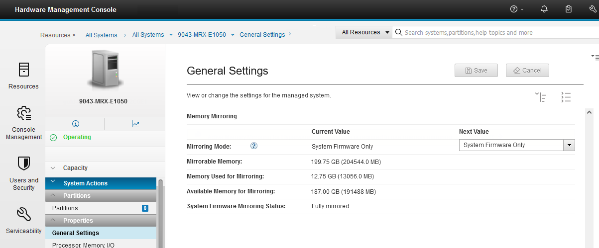
Figure 2-12 Memory Mirroring section in the General Settings window on the HMC enhanced GUI
After a failure occurs on one of the DDIMMs that contains hypervisor data, all the server operations remain active and the enterprise Baseboard Management Controller (eBMC) service processor isolates the failing DDIMMs. The system stays in the partially mirrored state until the failing DDIMM is replaced.
Memory that is used to hold the contents of platform dumps is not mirrored, and AMM does not mirror partition data. AMM mirrors only the hypervisor code and its components to protect this data against a DDIMM failure. With AMM, uncorrectable errors in data that are owned by a partition or application are handled by the existing Special Uncorrectable Error (SUE) handling methods in the hardware, firmware, and OS.
SUE handling prevents an uncorrectable error in memory or cache from immediately causing the system to stop. Rather, the system tags the data and determines whether it will be used again. If the error is irrelevant, it does not force a checkstop. If the data is used, termination can be limited to the program/kernel or hypervisor owning the data, or freeze of the I/O adapters that are controlled by an I/O hub controller if data must be transferred to an I/O device.
2.3 Internal I/O subsystem
The internal I/O subsystem of the Power E1050 server is connected to the PCIe Express controllers on a Power10 chip in the system. A Power10 chip has two PCI Express controllers (PECs) of 16 lanes each for a total of 32 Gen5/Gen4 lanes per chip and 64 Gen5/Gen4 lanes per DCM.
Each PEC supports up to three PCI host bridges (PHBs) that directly connect to PCIe slots or devices. Both PEC0 and PEC1 can be configured as follows:
•One x16 Gen4 PHB or one x8 Gen5 PHB
•One x8 Gen5 and one x8 Gen4 PHB
•One x8 Gen5 PHB and two x4 Gen4 PHBs
The usage or configurations of the PECs are shown in the notation of the ports. There are two notations, the E-Bus notation and the PHB notation, which describe the split of the PEC. Table 2-9 gives an overview.
Table 2-9 PHB cross-reference to E-Bus notation
|
PEC configuration
|
E-Bus ports
|
PHB
|
|
One x16 at DCM0
|
E0
|
PHB0
|
|
Two x8 at DCM0
|
E0A and E0B
|
PHB0 and PHB1
|
|
One x8 and two x4 at DCM0
|
E0A, E0B, and E0C
|
PHB0, PHB1, and PHB2
|
|
One x16 at DCM1
|
E1
|
PHB3
|
|
Two x8 at DCM1
|
E1A and E1B
|
PHB3 and PHB4
|
|
One x8 and two x4 at DCM1
|
E1A, E1B, and E1C
|
PHB3, PHB4, and PHB5
|
Figure 2-13 shows a diagram of the I/O subsystem of the Power E1050 server. The left (front) DCM0 and DCM3 are placed in a 180-degrees rotation compared to the two right (rear) DCM1 and DCM2 to optimize PCIe slots and NVMe bay wirings.

Figure 2-13 Power E1050 I/O subsystem diagram
On the left (front) side, you find 10 NVMe bays. Six NVMe bays are connected to DCM0 and four NVMe bays are connected to DCM3. To make all 10 NVMe bays available, all four processor sockets must be populated. The NVMe bays are connected mainly by using a x8 PHB, some with a x4 PHB. But because the NVMe devices can use four lanes (x4), this fact is not relevant from a performance point of view.
On the right (rear) side, you find 11 PCIe slots in a different manner. Six slots use up to 16 lanes (x16) and can operate either in PCI Gen4 x16 mode or in Gen5 x8 mode. The remaining five slots are connected with eight lanes. Two of them are Gen5 x8, and three of them are Gen4 x8. In a 2-socket processor configuration, seven slots are available for use (P0-C1 and P0-C6 to P0-C11). To make all the slots available, at least three processor sockets must be populated.
The x16 slots can provide up to twice the bandwidth of x8 slots because they offer twice as many PCIe lanes. PCIe Gen5 slots can support up to twice the bandwidth of a PCIe Gen4 slot, and PCIe Gen4 slots can support up to twice the bandwidth of a PCIe Gen3 slot, assuming an equivalent number of PCIe lanes.
|
Note: Although some slots provide a x8 connection only, all slots have an x16 connector.
|
All PCIe slots support hot-plug adapter installation and maintenance and enhanced error handling (EEH). PCIe EEH-enabled adapters respond to a special data packet that is generated from the affected PCIe slot hardware by calling system firmware, which examines the affected bus, allows the device driver to reset it, and continues without a system restart. For Linux, EEH support extends to the most devices, although some third-party PCI devices might not provide native EEH support.
All PCIe adapter slots support hardware-backed network virtualization through single-root IO virtualization (SR-IOV) technology. Configuring an SR-IOV adapter into SR-IOV shared mode might require more hypervisor memory. If sufficient hypervisor memory is not available, the request to move to SR-IOV shared mode fails. The user is instructed to free extra memory and try the operation again.
The server PCIe slots are allocated DMA space by using the following algorithm:
•All slots are allocated a 2 GB default DMA window.
•All I/O adapter slots (except the embedded Universal Serial Bus (USB)) are allocated Dynamic DMA Window (DDW) capability based on installed platform memory. DDW capability is calculated assuming 4 K I/O mappings:
– The slots are allocated 64 GB of DDW capability.
– Slots can be enabled with Huge Dynamic DMA Window (HDDW) capability by using the I/O Adapter Enlarged Capacity setting in the ASMI.
– HDDW-enabled slots are allocated enough DDW capability to map all installed platform memory by using 64 K I/O mappings.
– Slots that are HDDW-enabled are allocated the larger of the calculated DDW capability or HDDW capability.
The Power E1050 server is smarter about energy efficiency when cooling the PCIe adapter environment. It senses which IBM PCIe adapters are installed in their PCIe slots, and if an adapter requires higher levels of cooling, they automatically speed up fans to increase airflow across the PCIe adapters. Faster fans increase the sound level of the server. Higher wattage PCIe adapters include the PCIe3 serial-attached SCSI (SAS) adapters and solid-state drive (SSD)/flash PCIe adapters (#EJ10, #EJ14, and #EJ0J).
USB ports
The first DCM (DCM0) also hosts the USB controller that is connected by using four PHBs, although the USB controller uses only one lane. DCM0 provides four USB 3.0 ports, with two in the front and two in the back. The two front ports provide up to 1.5 A USB current, mainly to support the external USB DVD (Feature Code EUA5). The two rear USB ports current capacity is 0.9 A.
|
Note: The USB controller is placed on the trusted platform module (TPM) card because of space reasons.
|
Some customers require that USB ports must be deactivated for security reasons. You can achieve this task by using the ASMI menu. For more information, see 2.5.1, “Managing the system by using the ASMI GUI” on page 73.
2.3.1 PCIe adapter slot details
The PCIe adapter slots have different characteristics. Table 2-10 lists the PCIe adapter slot locations, the slot type, the connection to the processor, the OpenCAPI capability, the support to host a PCIe Gen4 cable card (#EJ2A) to attach the EMX0 PCIe Gen3 I/O expansion drawer, and the I/O adapter enlarged capacity enablement order.
Table 2-10 PCIe slot locations and capabilities for the Power E1080 servers
|
Location code
|
Description
|
Processor module
|
OpenCAPI
|
Cable card for I/O drawer
|
I/O adapter enlarged capacity enablement order1
|
|
P0-C02
|
eBMC
|
DCM0-P0-E0-PHB1
|
N/A
|
N/A
|
N/A
|
|
P0-C13
|
PCIe4 x8
|
DCM0-P0-E0-PHB0
|
Yes
|
No
|
9
|
|
P0-C2
|
PCIe5 x8 or PCIe4 x16
|
DCM2-P1-E1-PHB3
|
Yes
|
Yes
|
1
|
|
P0-C3
|
PCIe5 x8 or PCIe4 x16
|
DCM2-P1-E0-PHB0
|
Yes
|
Yes
|
5
|
|
P0-C4
|
PCIe5 x8 or PCIe4 x16
|
DCM2-P0-E1-PHB3
|
No
|
Yes
|
2
|
|
P0-C5
|
PCIe5 x8 or PCIe4 x16
|
DCM2-P0-E0-PHB0
|
No
|
Yes
|
6
|
|
P0-C6
|
PCIe4 x8
|
DCM1-P1-E1-PHB4
|
Yes
|
No
|
10
|
|
P0-C7
|
PCIe5 x8
|
DCM1-P1-E1-PHB3
|
Yes
|
Yes
|
7
|
|
P0-C8
|
PCIe5 x8 or PCIe4 x16
|
DCM1-P1-E0-PHB0
|
Yes
|
Yes
|
3
|
|
P0-C9
|
PCIe4 x8
|
DCM1-P0-E1-PHB4
|
Yes
|
No
|
11
|
|
P0-C10
|
PCIe5 x8
|
DCM1-P0-E1-PHB3
|
Yes
|
Yes
|
8
|
|
P0-C11
|
PCIe5 x8 or PCIe4 x16
|
DCM1-P0-E0-PHB0
|
Yes
|
Yes
|
4
|
1 Enabling the I/O adapter enlarged capacity option affects only Linux partitions.
2 Only used for an eBMC card.
3 P0-C1 is generally used for the base Ethernet adapter.
The following characteristics are not part of the table because they apply for all slots:
•All slots are SR-IOV capable.
•All slots have an x16 connector, although some provide only a x8 connection.
•All PCIe adapters are installed in an I/O Blind-Swap Cassette (BSC) as the basis for concurrent maintenance. For more information, see 2.3.2, “I/O Blind-Swap Cassettes” on page 69.
•All I/O cassettes can hold Half Length Full Height (HLFH) and Half Length Half Height (HLHH) PCIe adapters.
Figure 2-14 shows the rear view of the Power E1050 server with the location codes for the PCIe adapter slots.

Figure 2-14 Rear view of a Power E1050 server with PCIe slots location codes
|
Note: Slot P0-C0 is not a PCIe slot; instead, it holds a special I/O Cassette for the eBMC Service Processor Card.
|
2.3.2 I/O Blind-Swap Cassettes
The Power E1050 server supports I/O BSCs for easy hot-plugging of PCIe adapters. PCIe adapters are installed inside a BSC before inserting it into the system from the rear. Each BSC has one x16 PCIe connector. There is always a BCS in each slot (C1 - C11), either with an adapter or a blank. All PCIe slots C1 - C11 are concurrently maintainable by using a BCS.
|
Caution: To hot plug a BCS, first go to the HMC or AIX diag to start a hot-plug action to remove the power from a slot. Do not pull a cassette when the slot is still under power.
|
Slot C0 is a special I/O cassette for the eBMC Service Processor card. The eBMC card is not concurrently maintainable. For more information, see 2.3.5, “System ports” on page 71.
Figure 2-15 is an illustration of the BCS. The Power E1050 I/O BSC is like the one for the Power E950 server, but it has an impel backplane connector to support Gen4 PCIe. Its lock latch is redesigned to include initial turns before engaging the BCS to make the latch more robust.

Figure 2-15 Power E1050 Blind-Swap Cassette
2.3.3 Non-volatile Memory Express bays
The IBM Power E1050 server has a 10-NVMe backplane that is always present in the server. It offers up to 10 NVMe bays with all four processor sockets populated and six NVMe bays if only two or three processor sockets are populated. It connects to the system board through three Molex Impact connectors and a power connector. There is no cable between the NVMe backplane and the system board.
The wiring strategy and backplane materials are chosen to ensure Gen4 signaling to all NVMe drives. All NVMe connectors are PCIe Gen4 connectors. For more information about the internal connection of the NVMe bays to the processor chips, see Figure 2-13 on page 66.
Each NVMe interface is a Gen4 x4 PCIe bus. The NVMe drives can be in an OS-controlled RAID array. A hardware RAID is not supported on the NVMe drives. The NVMe thermal design supports 18 W for 15-mm NVMe drives and 12 W for 7-mm NVMe drives.
For more information about the available NVMe drives and how to plug the drives for best availability, see 3.5, “Internal storage” on page 92.
2.3.4 Attachment of I/O-drawers
The Power E1050 server can expand the number of its I/O slots by using I/O Expansion Drawers (#EMX0). The number of I/O drawers that can be attached to an Power E1050 server depends on the number of populated processor slots, which changes the number of available internal PCIe slots of the server. Only some slots can be used to attach an I/O Expansion Drawer by using the #EJ2A CXP Converter adapter, also referred to as a cable card.
Feature Code #EJ2A is an IBM designed PCIe Gen4 x16 cable card. It is the only supported cable card to attach fanout modules of an I/O Expansion Drawer in the Power E1050 server. Previous cards from a Power E950 server cannot be used. Feature Code #EJ2A supports copper and optical cables for the attachment of a fanout module.
|
Note: The IBM e-config configurator adds 3-meter copper cables (Feature Code #ECCS) to the configuration if no cables are manually specified. If you want to have optical cables make sure to configure them.
|
Table 2-11 lists the PCIe slot order for the attachment of an I/O Expansion Drawer, the maximum number of I/O Expansion Drawers and Fanout modules, and the maximum number of available slots (dependent on the populated processor sockets).
Table 2-11 I/O Expansion Drawer capabilities depend on the number of populated processor slots
|
Processor sockets populated
|
Expansion adapter slots order
|
Maximum number of I/O Expansion Drawers
|
Maximum number of fanout modules
|
Total PCIe slots
|
|
DCM0 and DCM1
|
P0-C8, P0-C11, P0-C7, and P0-C10
|
2
|
4
|
27
|
|
DCM0, DCM1, and DCM2
|
P0-C8, P0-C11, P0-C2, P0-C3, P0-C4, and P0-C5
|
3
|
6
|
41
|
|
DCM0, DCM1, DCM2, and DCM3
|
P0-C8, P0-C11, P0-C2, P0-C3, P0-C4, P0-C5, P0-C7, and P0-C10
|
4
|
8
|
51
|
For more information about the #EMX0 I/O Expansion Drawer, see 3.9.1, “PCIe Gen3 I/O expansion drawer” on page 99.
2.3.5 System ports
The Power E1050 server has two 1-Gbit Ethernet ports and two USB 2.0 ports to connect to the eBMC service processor. The two eBMC Ethernet ports are used to connect one or two HMCs. There are no other HMC ports, as in servers that have a Flexible Service Processor (FSP). The eBMC USB ports can be used for a firmware update from a USB stick.
The two eBMC Ethernet ports are connected by using four PCIe lanes each, although the eBMC Ethernet controllers need only one lane. The connection is provided by the DCM0, one from each Power10 chip. For more information, see Figure 2-13 on page 66.
The eBMC module with its two eBMC USB ports also is connected to the DCM0 at chip 0 by using a x4 PHB, although the eBMC module uses only one lane.
For more information about attaching an Power E1050 server to an HMC, see Accessing the eBMC so that you can manage the system.
For more information about how to do a firmware update by using the eBMC USB ports, see Installing the server firmware on the service processor or eBMC through a USB port.
2.4 Component summary per processor socket configuration
The Power E1050 server is modular and every populated processor module activates more features and ports. This section provides an overview about the features that are available in a 2-, 3-, and 4-processor configurations.
The following features are available in a 2-socket configuration:
•Two processor sockets for two Power10 processors with 24 - 48 cores (installed)
•Thirty-two OMI memory ports for 256 GB, with up to 8 TB of memory
•Seven PCIe ports:
– Two PCIe Gen4 x16 / PCIe Gen5 x8
– Two PCIe Gen5 x8
– Three PCIe Gen4 x8
•Up to two I/O Expansion drawers supporting:
– Four fanout modules
– Twenty-seven PCIe slots (server total)
•Six individual NVMe ports supporting up to 38.4 TB
•Four USB 3.0 ports
•Two eBMC 1-Gbit Ethernet ports
•Two eBMC 2.0 USB ports
The following features are available in a 3-socket configuration:
•Three processor sockets for three Power10 processors with 36 - 72 cores (installed)
•Forty-eight OMI memory ports for 384 GB, with up to 12 TB of memory
•Eleven PCIe ports:
– Six PCIe Gen4 x16 / PCIe Gen5 x8
– Two PCIe Gen5 x8
– Three PCIe Gen4 x8
•Up to three I/O Expansion drawers supporting:
– Six fanout modules
– Forty-one PCIe slots (server total)
•Six individual NVMe ports supporting up to 38.4 TB
•Four USB 3.0 ports
•Two eBMC 1-Gbit Ethernet ports
•Two eBMC 2.0 USB ports
The following features are available in a 4-socket configuration:
•Four processor sockets for four Power10 processors with 48 - 96 cores (installed)
•Sixty-four OMI memory ports for 512 GB, with up to 16 TB of memory
•Eleven PCIe ports:
– Six PCIe Gen4 x16 / PCIe Gen5 x8
– Two PCIe Gen5 x8
– Three PCIe Gen4 x8
•Up to four I/O Expansion drawers supporting:
– Eight fanout modules
– Fifty-one PCIe slots (server total)
•Ten individual NVMe ports supporting up to 64 TB
•Four USB 3.0 ports
•Two eBMC 1-Gbit Ethernet ports
•Two eBMC 2.0 USB ports
2.5 The enterprise Baseboard Management Controller
The Power E1050 server and the Power10 scale-out systems use an eBMC for system service management, monitoring, maintenance, and control. The eBMC also provides access to the system event log (SEL) files. The eBMC is a specialized service processor that monitors the physical state of the system by using sensors. A system administrator or service representative can communicate with the eBMC through an independent connection.
2.5.1 Managing the system by using the ASMI GUI
The ASMI is the GUI to the eBMC. It is similar in terms of its function to the ASMI of FSP-managed servers (for example, the Power E1080 server), but it is a complete redesign of the UI driven through customer feedback of a Design Thinking workshop.
To enter the ASMI GUI, go to an HMC, select the server, and then select Operations → Launch Advanced System Management. A window opens and shows the name of the system, MTM and serial number, and the IP address of the service processor (eBMC). Click OK, and the ASMI window opens.
If the eBMC is not in a private but reachable network, you can connect directly by entering https://<eBMC IP> into your web browser.
Figure 2-16 show the login window for the ASMI.

Figure 2-16 ASMI login window
The default user when you log in the first time is admin and the default password is also admin but invalidated. After the first login, you must immediately change the admin password, which is also true after performing a factory reset of the system. This policy change ensures that the eBMC is not left in a state with a well-known password. The password needs to be a strong one, and not, for example, abcd1234. For more information about the password rules, see Setting the password.
After login, you see the Overview page with server, firmware, network, power, and status information, as shown in Figure 2-17.

Figure 2-17 ASMI Overview window
The new ASMI for eBMC managed servers have some major differences and some valuable new features:
•System firmware updates
It is possible to install a firmware update for the server by using the ASMI GUI, even if the system is managed by an HMC. In this case, the firmware update is always disruptive. To install a concurrent firmware update, you must use the HMC.
•Download of dumps
Dumps can be downloaded by using the HMC, but if necessary, you also can download them from the ASMI menu.
It is also possible to initiate a dump from the ASMI by selecting Logs → Dumps, selecting the dump type, and clicking Initiate dump. The possible dump types are:
– Baseboard management controller (BMC) dump (nondisruptive)
– Resource dump
– System dump (disruptive)
•Network Time Protocol (NTP) server support
•Lightweight directory access protocol (LDAP) for user management
•Host console
By using the host console, you can watch the boot process of the server. The host console also can be used to access the OS if there is only a single LPAR using all resources.
|
Note: The host console can also be accessed by using an SSH client over port 2200 and logging in with the admin user.
|
•User management
In the eBMC, it is possible to create you own users. This feature also can be used to create an individual user that can be used for the HMC to access the server. There are two types of privileges for a user: Administrator or ReadOnly. As the name indicates, with the ReadOnly privileges, you cannot modify something (except the password of that user), and a user with that privilege cannot be used for HMC access to the server.
•IBM Security® through Access Control Files (ACFs)
In FSP-managed servers, IBM Support generates a password by using the serial number and the date to get “root access” to the service processor by using the user celogin. In eBMC managed systems, IBM support generates an ACF. This file must be uploaded to the server to get access. This procedure is, for example, needed if you lost the admin password and want to reset it.
•Jumper reset
It is possible to reset everything on the server by using a jumper. This reset is a factory reset that resets everything, like LPARs, eBMC settings, or the NVRAM.
Real-time progress indicator
The ASMI of an eBMC server also provides a real-time progress indicator to see the operator panel codes. To open the windows that show the codes, select Logs → Progress logs, and then click View code in real time.
Inventory and LEDs
Under the Hardware status → Inventory and LEDs menu, you find most of the hardware components with their state and an identification LED, and the system identify LED and the System attention LED. You can turn on and off all identification LEDs. Only the System attention LED can be turned off.
It is also possible to display the details of a component, which is helpful to see details such as the size of a DIMM or the part numbers if something must be exchanged.
Sensors
The ASMI has many sensors for the server, which you can access by selecting Hardware status → Sensors. The loading of the sensors takes some time, and during that time you see a progress bar on the top of the window.
|
Note: Although the progress bar might be finished, it might take some extra time until the sensors appear.
|
Figure 2-18 shows an example of the Sensors window.
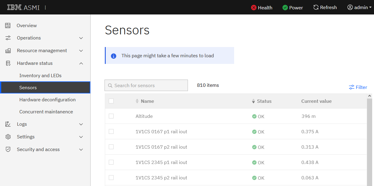
Figure 2-18 ASMI Sensors window
Network settings
The default network setting for the two eBMC ports is DHCP. Therefore, when you connect a port to a private HMC network where the HMC is connected to a DHCP server, the new system should get its IP address from the HMC during the startup of the firmware. Then, the new system automatically appears in the HMC and can be configured. DHCP is the IBM recommended way to attach a server to the HMC.
If you do not use DHCP and want to use a static IP address, you can set the IP address in the ASMI GUI. However, because there are no default IP addresses that are the same for every server, you first must discover the configured IP address.
To discover the configured IP address, use the operator panel and complete the following steps:
1. Use the Increment or Decrement buttons to scroll to function 02.
2. Press Enter until the value changes from N to M, which activates access to function 30.
3. Scroll to function 30 and press Enter. Function 30** appears.
4. Scroll to 3000 and press Enter, which shows you the IP address of the eth0 port.
5. If you scroll to 3001 and press Enter, you see the IP address of eth1.
6. After you discover the IP address, scroll again to function 02 and set the value back from M to N.
For more information about function 30 in the operator panel, see IBM Documentation.
Now that you have discovered the IP address, you can connect any computer with a web browser to an IP address in the same subnet (class C) and connect the computer with the correct Ethernet port of the Power E1050 server.
|
Hint: Most connections work by using a standard Ethernet cable. If you do not see a link when using a standard Ethernet cable, try a crossover cable, where the send and receive wires are crossed.
|
After connecting the cable, you can use a web browser to access the ASMI by using the URL https://<IP address>, and then you can configure the network ports. To configure the network ports, select Settings → Network and select the correct adapter to configure. Figure 2-19 shows an example of changing eth1. Before you can configure a static IP address, turn off DHCP. It is possible to configure several static IP addresses on one physical Ethernet port.

Figure 2-19 ASMI network settings
You cannot configure the Virtualization Management Interface (VMI) address in the ASMI network settings. The VMI address is another IP address that is configured on the physical eBMC Ethernet port of the server to manage the virtualization of the server. The VMI address can be configured only in the HMC.
Using an Access Control File
If you lose the access password for the ASMI service user, you can access the ASMI by using an ACF. An ACF is a digital certificate that is provided by IBM Support when you open a support case. To use the ACF, the system must be enabled at the server by using the operator panel.
Complete the following steps:
1. On the operator panel, use the Increment or Decrement buttons to scroll to function 74.
2. Press Enter, and select 00 to accept the function (FF rejects it).
3. The ACF function now is active for 30 minutes. To use it, access the ASMI login window.
4. To upload the ACF into the system and access the ASMI, click Upload service login certificate.
For more information, see IBM Documentation.
Policies
In the Security and access → Policies menu, you can turn on and off security-related functions, for example, whether you can manage your server by using Intelligent Platform Management Interface (IPMI).
Some customers require that the USB ports of the server should be disabled. You can accomplish this task by using policies. To do so, clear Host USB enablement, as shown in Figure 2-20.
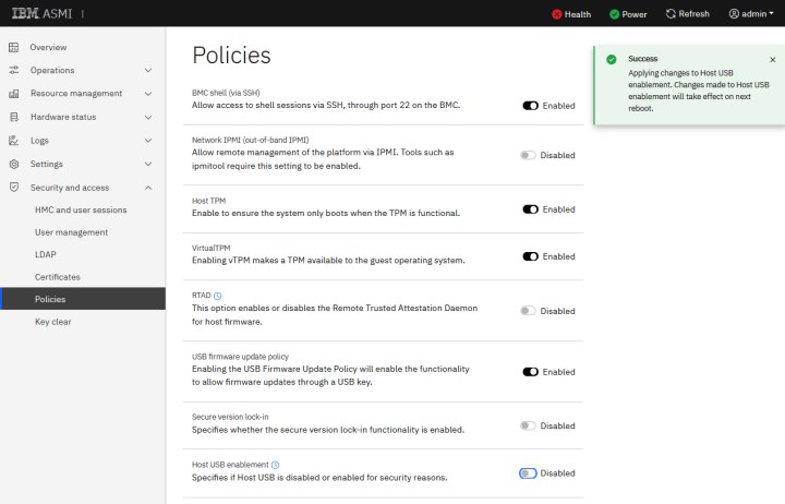
Figure 2-20 How to turn off the USB ports of the server
2.5.2 Managing the system by using DMTF Redfish
eBMC-based systems can be managed by using the DMTF Redfish application programming interfaces (APIs). Redfish is a Representational State Transfer (REST) API that is used for platform management and is standardized by the Distributed Management Task Force, Inc.
There are multiple ways of working with Redfish. One possibility is to use the OS command curl. The following examples show how to work with curl and Redfish.
Before you can get data from the server or run systems management tasks by using Redfish, you must authenticate against the server. After you authenticate by using a user ID and password, you receive a token from the serve that you use later.
Example 2-1 show how to obtain a token.
Example 2-1 Obtaining a token from Redfish
# export eBMC=<IP>
# export USER=admin
# export PASSWORD=<PW>
# export TOKEN=`curl -k -H "Content-Type: application/json" -X POST https://${eBMC}/login -d "{"username" : "${USER}", "password" : "${PASSWORD}"}" | grep token | awk '{print $2;}' | tr -d '"'`
With the token, you can get data from the server. First, request the data of the Redfish root by using /Redfish/v1. You get data with additional branches in the Redfish tree, for example, Chassis (uppercase C). To dig deeper, use the newly discovered odata.id /Redfish/v1/Chassis, as shown in Example 2-2.
Example 2-2 Getting chassis data from Redfish
#curl -s -k -H "X-Auth-Token: $TOKEN" -X GET https://${eBMC}/redfish/v1
{
"@odata.id": "/redfish/v1",
"@odata.type": "#ServiceRoot.v1_12_0.ServiceRoot",
"AccountService": {
"@odata.id": "/redfish/v1/AccountService"
},
"Cables": {
"@odata.id": "/redfish/v1/Cables"
},
"CertificateService": {
"@odata.id": "/redfish/v1/CertificateService"
},
"Chassis": {
"@odata.id": "/redfish/v1/Chassis"
},
# curl -k -H "X-Auth-Token: $TOKEN" -X GET https://${eBMC}/Redfish/v1/Chassis
{
"@odata.id": "/Redfish/v1/Chassis",
"@odata.type": "#ChassisCollection.ChassisCollection",
"Members": [
{
"@odata.id": "/Redfish/v1/Chassis/chassis"
}
],
"[email protected]": 1,
"Name": "Chassis Collection"
# curl -k -H "X-Auth-Token: $TOKEN" -X GET https://${eBMC}/Redfish/v1/Chassis/chassis
{
"@odata.id": "/Redfish/v1/Chassis/chassis",
"@odata.type": "#Chassis.v1_16_0.Chassis",
"Actions": {
...
"PCIeSlots": {
"@odata.id": "/Redfish/v1/Chassis/chassis/PCIeSlots"
},
...
"Sensors": {
"@odata.id": "/Redfish/v1/Chassis/chassis/Sensors"
},
...
Under Chassis (uppercase C), there is another chassis with a lowercase c. Use the tree with both (/Redfish/c1/Chassis/chassis). After running the chassis, you can see in Example 2-2 on page 80 for example, that there are PCIeSlots and Sensors, among other resources of the server.
In Example 2-3, you can see what is under Sensors. There you can find the same sensors as in the ASMI GUI (see Figure 2-18 on page 77). In the output, you find, for example, the sensor total_power. When you ask for details about that sensor, as shown in Example 2-3, you can see that the server needed 1.426 watts at the time of running the command.
Example 2-3 Getting sensor data from Redfish
# curl -k -H "X-Auth-Token: $TOKEN" -X GET https://${eBMC}/Redfish/v1/Chassis/chassis/Sensors
{
"@odata.id": "/Redfish/v1/Chassis/chassis/Sensors",
"@odata.type": "#SensorCollection.SensorCollection",
"Description": "Collection of Sensors for this Chassis",
"Members": [
{
"@odata.id": "/Redfish/v1/Chassis/chassis/Sensors/Altitude"
},
{
"@odata.id": "/Redfish/v1/Chassis/chassis/Sensors/1V1CS_0167_p1_rail_iout"
},
...
{
"@odata.id": "/Redfish/v1/Chassis/chassis/Sensors/total_power"
},
# curl -k -H "X-Auth-Token: $TOKEN" -X GET https://${eBMC}/Redfish/v1/Chassis/chassis/Sensors/total_power
{
"@odata.id": "/Redfish/v1/Chassis/chassis/Sensors/total_power",
"@odata.type": "#Sensor.v1_0_0.Sensor",
"Id": "total_power",
"Name": "total power",
"Reading": 1426.0,
"ReadingRangeMax": null,
"ReadingRangeMin": null,
"ReadingType": "Power",
"ReadingUnits": "W",
"Status": {
"Health": "OK",
"State": "Enabled"
}
Some other useful strings to ask for are shown in Example 2-4.
Example 2-4 Other useful Redfish data
#Type and model of the server
# curl -s -k -H "X-Auth-Token: $TOKEN" -X GET https://${eBMC}/Redfish/v1/Systems/system | grep Model | grep -v SubModel | grep -v ""
"Model": "9043-MRX",
#Serial number
# curl -s -k -H "X-Auth-Token: $TOKEN" -X GET https://${eBMC}/redfish/v1/Systems/system | grep SerialNumber
"SerialNumber": "<SN>",
#Type, model, and serial number
#curl -s -k -H "X-Auth-Token: $TOKEN" -X GET https://${eBMC}/redfish/v1/Systems/system | grep AssetTag
"AssetTag": "Server-9043-MRX-<SN>",
#System indicator LED
#curl -s -k -H "X-Auth-Token: $TOKEN" -X GET https://${eBMC}/redfish/v1/Systems/system | grep IndicatorLED
"IndicatorLED": "Off",
#Total memory
# curl -s -k -H "X-Auth-Token: $TOKEN" -X GET https://${eBMC}/redfish/v1/Systems/system | grep TotalSystemMemoryGiB
"TotalSystemMemoryGiB": 8192
#Power state
# curl -s -k -H "X-Auth-Token: $TOKEN" -X GET https://${eBMC}/redfish/v1/Systems/system | grep PowerState
"PowerState": "On",
It is also possible to run operations on the server by using the POST method with the Redfish API interface. In Example 2-5, you can see the curl commands that can start or stop the server.
Example 2-5 POST command examples for Redfish
#Power on server
# curl -k -H "X-Auth-Token: $TOKEN" -X POST https://${eBMC}/redfish/v1/Systems/
system/Actions/Reset -d '{"ResetType":"On"}'
#Power off server
# curl -k -H "X-Auth-Token: $TOKEN" -X POST https://${eBMC}/redfish/v1/Systems/
system/Actions/Reset -d '{"ResetType":"ForceOff"}'
For more information about Redfish, see Managing the system by using DMTF Redfish APIs. For more information about how to work with Redfish in IBM Power servers, see Managing Power Systems servers by using DMTF Redfish APIs.
2.5.3 Managing the system by using the IPMI
The Power E1050 server can also be managed by using the IPMI, but the IPMI is disabled by default on your server. Inherent security vulnerabilities are associated with the IPMI, so consider using Redfish APIs or the GUI to manage your system.
If you want to use IPMI, you first must enable it. To do so, select Security and access → Policies. Then, enable the policy Network IPMI (out-of-band IPMI).
A list of common IPMI commands can be found at Common IPMI commands.
2 Giga-transfers per second (GTps).
3 The OMI links are also referred to as OMI subchannels.
4 A-busses and X-busses provide SMP fabric ports, which are used between central electronic complex (CEC) drawers or within CEC drawers respectively.
..................Content has been hidden....................
You can't read the all page of ebook, please click here login for view all page.