
Structural Properties
High-entropy alloys have been shown to have promising properties for a wide range of applications. For different applications, different critical properties are emphasized in the product design and materials selection. This chapter will focus on mechanical, wear, electrochemical, and oxidation properties, which are often basic or critical considerations for structural stability and lifetime in various applications. In the presentation of properties, alloy composition, processes, and microstructure are also correlated to give a better understanding on the phenomena and mechanisms. Based on this, it will be shown that there is a large space to further design composition and selection. There is scope to improve structural properties for specific purposes and applications.
Keywords
Mechanical property; wear behavior; electrochemical property; oxidation behavior
8.1 Introduction
HEAs have such promising properties that they are considered as potential candidates for a wide range of applications such as high temperature, electronic, magnetic, anticorrosion, and wear-resistant applications. Many of these properties arise out of their unique structural feature, a multicomponent solid solution. In some cases, HEAs show nanoscale precipitates, which further enhance some of the properties of these alloys. This chapter deals with various structural properties of HEAs including mechanical, wear, electrochemical, and oxidation.
8.2 Mechanical Properties
Mechanical properties cover hardness, elastic modulus, yield strength, ultimate strength, elongation, fatigue, and creep. Structural applications require adequate combinations of these properties. For high-temperature applications, resistance to creep, oxidation and sulfidation (hot corrosion) are taken into account in the material-selection requirements. As a result, studies of mechanical properties of HEAs are important to demonstrate that this new class of alloys have better performance than that of conventional alloys for specific applications. In addition, as HEAs comprise multiprincipal elements and have pronounced core effects as mentioned previously, the mechanisms of structure-property correlations might not be an extension of those based on conventional alloys. Scientific understanding and verification of these correlations becomes an important basic issue.
8.2.1 Room-Temperature Mechanical Properties
Different alloys including refractory HEAs are described in this section. Cast and wrought processes, and powder metallurgy route including mechanical alloying and hot isostatic pressing, are used for synthesis. Hardness, compressive, tensile, fatigue properties, and deformation behavior are discussed.
The first system that has been studied extensively is the AlxCoCrCuFeNi alloys (Tong et al., 2005a, 2005b; Tung et al., 2007; Tsai et al., 2009b). The hardness of the system increases from 133 HV for x=0–0.5 to 655 HV for x=3.0 (Figure 8.1). This can be attributed to the increase in lattice distortion as Al is the largest atom amongst the constituents of the alloy (Callister, 2003). In addition, Al forms strong bonds with other elements in the alloy as reflected in the enthalpy of mixing (Miedema et al., 1980; Takeuchi and Inoue, 2010). Hence the solid solution strengthening effect increases with higher Al content. It was also observed that as the Al content increases the phase changes from FCC to BCC (including disordered BCC and ordered BCC (B2)). The BCC and B2 phases are stronger than the FCC phase. Apart from this, nanoprecipitates formed due to slow diffusion kinetics also strengthen the material. The SD BCC+B2 modulated structure occurring in the BCC DR regions further strengthens the material (Yeh et al., 2004b; Tong et al., 2005a, 2005b). The cracks due to the indents, whose total length is an indication of toughness, are not present for the compositions where FCC phase is dominant (Figure 8.1). But, as the x value increases such that a BCC phase starts to dominate, the cracks start to appear. The length of the crack increases with increased amount of BCC phase, which indicates increased brittleness. Li et al. (2009) reported similar effect of Al on hardness. Addition of V to the Al0.5CoCrCuFeNi alloy to synthesize Al0.5CoCrCuFeNiVx alloy increases the hardness (Chen et al., 2006a). After x=0.4, the BCC phase becomes the DR phase and increases in volume fraction from thereon. Also a σ phase forms after x=0.6, which further contributes to the hardness of the alloy.

Alloying elements with larger atomic sizes have a tendency to form secondary phases and cause precipitation strengthening. For example, among the 10 systems studied by Li et al. (2009), the highest hardness (566 HV) was achieved with the addition of Zr and Ti, which have larger atomic size and cause precipitation of secondary phases. Ma and Zhang (2012) reported that Nb addition from x=0 to 0.5 increases the hardness of AlCoCrFeNbxNi alloy from 500 to 750 HV. Combined additions of Ti and Nb increase the hardness to 797 HV, which is higher than that achieved by adding only one of these two elements (Razuan et al., 2013). In another report (Hsu et al., 2010a), AlCoCrFexMo0.5Ni alloy’s hardness was reported to decrease with an increase in Fe, because the alloy has a soft BCC phase and a harder σ phase in the microstructure. As the amount of Fe increases, the amount of BCC phase increases at the expense of σ phase causing a drop in hardness and wear resistance as shown in Figure 8.2. Similar to Fe, increase in Co content in AlCoxCrFeMo0.5Ni decreases the hardness from 788 HV at x=0.5 to 596 HV at x=2.0 (Hsu et al., 2010b).

The AlCoCrFeNiTix alloys showed good mechanical properties in compression (Zhou et al., 2007b, 2008a). The composition with x=0.5 had a BCC structure and was found to give optimum properties. The yield strength and fracture strength were found to be 2.26 and 3.14 GPa, respectively, which are much higher than that of BMGs. The alloy also had a 23.3% plastic elongation. The high strength was attributed to the spinodal decomposition in DR region, while there was precipitation of BCC phase particles in the ID region. Thus apart from solid solution strengthening, nanoparticle and precipitation strengthening also play an important role.
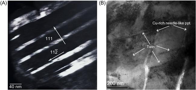
The major deformation mechanism in the Al0.5CoCrCuFeNi alloy has been found to be twinning but not slip (Tsai et al., 2009b). This is different from that in conventional FCC alloys in which twinning is not commonly observed. One evidence is that etch pits that were observed in the presence of slip bands were absent in the microstructure and TEM did not reveal dislocation tangles. Figure 8.3 shows the dark-field and bright-field images of the nanotwins formed between the Widmanstätten precipitates and their plane and direction for the 5% cold-rolled alloy (Tsai et al., 2009b). This suggests that nanotwinning in this HEA starts in the initial stage of plastic deformation itself. This is because there are nanoscale precipitates distributed throughout the matrix of DR and slip movement is easily arrested. One more reason is that presence of large number of elements in HEA alloys causes Suzuki interaction, which significantly reduces the stacking fault energy (SFE), thus making it easier for twinning. Hence, nanotwinning occurs because the twin nucleation is initiated at nanoscale region between the Widmanstätten precipitates. Similar nanotwins have also been observed in CoCrFeNi HEA obtained by mechanical alloying followed by SPS. AlCoCrCuFeNi alloy made by splat quenching and casting was compared by Singh et al. (2011b). The hardness values of splat-quenched (539 HV) and as-cast (534 HV) alloys are almost equal. However, the indentation elastic modulus of the as-cast material (182 GPa) is markedly higher than that of the splat-quenched alloy (105 GPa).
In a single-phase FCC CoCrFeMnNi alloy (Otto et al., 2013a), it was found that the deformation is governed by planar slip of 1/2![]() 110
110![]() type dislocations on
type dislocations on ![]() 111
111![]() planes at strains <2.4%, which also indicates low SFE. At a strain above 20%, the prevalence of deformation twinning was observed at 77 K, but the formation of dislocation cell structures was observed at 293 K. The evolution of microstructure and texture after heavy cold rolling and annealing in the same CoCrFeMnNi HEA was also reported (Bhattacharjee et al., 2014). A predominantly brass-type texture after 90% cold rolling was observed indicating the low SFE of this alloy. They proposed that the combined effect of high energy level of the distorted matrix and the strain energy relief of stacking fault by in situ atom position adjustment results in very low SFE as compared with conventional alloys featured by the small-distorted matrix with a host element.
planes at strains <2.4%, which also indicates low SFE. At a strain above 20%, the prevalence of deformation twinning was observed at 77 K, but the formation of dislocation cell structures was observed at 293 K. The evolution of microstructure and texture after heavy cold rolling and annealing in the same CoCrFeMnNi HEA was also reported (Bhattacharjee et al., 2014). A predominantly brass-type texture after 90% cold rolling was observed indicating the low SFE of this alloy. They proposed that the combined effect of high energy level of the distorted matrix and the strain energy relief of stacking fault by in situ atom position adjustment results in very low SFE as compared with conventional alloys featured by the small-distorted matrix with a host element.
Using refractory elements (melting points higher than 1650°C) as constituents, the American Air Force Research Laboratory developed refractory HEAs in order to overcome the temperature limitation associated with conventional superalloys. The room-temperature compressive yield stress of the first reported alloys MoNbTaW and MoNbTaVW was found to be 1058 and 1246 MPa, respectively. The quaternary MoNbTaW alloy showed a maximum strength of 1211 MPa and failed after 2.1% strain by a splitting mechanism (Senkov et al., 2010, 2011b). The Young’s modulus of this alloy was 220±20 GPa. On the other hand, the quinary alloy MoNbTaVW showed a maximum strength of 1270 MPa and failed after 1.7% strain by the same mechanism. The Young’s modulus of this alloy was 180±15 GPa. The failure occurred in a quasi-cleavage fashion parallel to the stress direction and hence in tensile mode.
Another refractory HEA HfNbTaTiZr, was also synthesized by arc melting (Senkov et al., 2011a). This alloy has a slightly lower yield stress of 929 MPa than the two refractory HEAs discussed above but deforms in compression up to 50% strain without any sign of fracture. This alloy showed good work hardening at a steady rate. Figure 8.4 shows uniform deformation behavior and evidences of twins and flow lines. Thus, the alloy can be strained to required strength and still has good ductility. Because most BCC alloys and ordered BCC (B2-type) intermetallic phases are brittle and tend to fracture by cleavage, this finding provides a good basis for developing ductile BCC alloys by modifying the composition.

Most of the studies measure only compressive properties. Yet, there are a few studies done exclusively to find out the tensile behavior of HEAs. Tensile behavior of the alloy Al0.5CoCrCuFeNi was studied on the cold-rolled sample with 80% reduction (Tsai et al., 2010a). At room temperature, the alloy showed yield strength of 1292 MPa, ultimate tensile strength of 1406 MPa, and elongation of 6%. Thus, this alloy has a combination of strength and ductility better than cold-rolled 304 stainless steels. These cold-rolled samples were further annealed at 900°C and their tensile properties were studied. The combination of yield strength (656 MPa), ultimate tensile strength (796 MPa), and elongation (29%) of this alloy is better than that of 304 stainless steel (310 and 620 MPa, and 30%, respectively). The alloy in the as-annealed state thus has remarkable mechanical properties for engineering applications.
Hemphill et al. (2012) were the first to study the fatigue behavior of an Al0.5CoCrCuFeNi HEA. The arc-melted samples were annealed at 1000°C for 6 h, water quenched, and cold rolled. The rolled sheets were subsequently machined to fatigue samples for four-point bending fatigue test. The fatigue investigation indicates that the fatigue behavior of HEAs compares favorably with that of many conventional alloys, such as steels, titanium alloys, and advanced BMGs with a fatigue endurance limit of between 540 and 945 MPa and a fatigue endurance limit to ultimate tensile strength ratio of between 0.402 and 0.703. The encouraging fatigue resistance demonstrates that Al0.5CoCrCuFeNi HEAs without surface defects may be useful in future applications where fatigue is a factor.
All the above studies on room-temperature mechanical properties are carried out on cast or wrought alloys. As discussed previously, when the alloys are manufactured by MA and sintering, usually better strength and hardness are achieved. The nanocrystalline nature of the structure causes the increase in hardness along with solid solution strengthening. Hardness of AlCrCuFeTiZn solid solution was 2 GPa in the MA-sintered condition. The same alloy when processed using MA-vacuum hot pressing (VHP) had a hardness of 9.50 GPa and compressive strength of 2.19 GPa and those after MA-hot isostatic pressing (HIP) were 10.04 and 2.83 GPa, respectively. Wear resistance of the alloy was found to be higher than that of the commercially used materials such as Ni-hard-faced alloy. Similarly, hardness and compressive strength of the AlCoCuNiTiZn HEA processed by MA-VHP were found to be 7.55 and 2.36 GPa, respectively. When HIP is used for the same alloys, hardness and compressive strength were 8.79 and 2.76 GPa, respectively (Varalakshmi et al., 2008, 2010a–c).
AlxCoCrCuFeNi (x=0.45, 1, 2.5, and 5) alloys synthesized by MA and SPS were studied by Sriharitha et al. (2014). Highest specific hardness of 960 HV was achieved in the sintered Al5CoCrCuFeNi alloy. Hall–Petch analysis based on hardness measurements carried out on sintered samples reveals that the contribution of solid solution strengthening and order strengthening, in comparison to grain size strengthening, increases with the increase in Al content (Figure 8.5).

Oxide-dispersed AlCoCrFe HEA synthesized by MA and SPS was studied by Praveen et al. (2013a). High hardness values of 1050 and 1070 HV were observed without and with oxide dispersion, respectively. It appears that solid solution strengthening effect in HEAs has superseded the effect of oxide dispersion. A hardness of 570 HV was achieved in CoCrFeNi alloy by the same synthesis technique (Praveen et al., 2013b).
8.2.2 High-Temperature Mechanical Properties
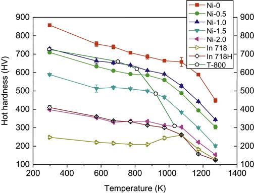
Due to sluggish diffusion effect and second-phase strengthening, HEAs might exhibit high strength at elevated temperatures. For example, AlCoxCrFeMo0.5Ni alloy (x=1) shows a hardness of 347 HV at 1273 K, which is higher than that of Ni-based superalloys IN 718/IN 718H by 220 HV (Hsu et al., 2010b). AlCoCrFeMo0.5Nix (x=0–1.5) also shows that hot hardness remains higher than that of superalloys IN 718 and IN 718H up to 1273 K (Figure 8.6). These alloys also possess a less negative value of softening coefficient (BII) at high-temperature regime compared with the same superalloys (Juan et al., 2013). Besides, AlCoCuNiTiZn alloy produced by MA-VHP was found to be stable at elevated temperature of about 800°C as it retained its nanostructure (Varalakshmi et al., 2010c).
MoNbTaW and MoNbTaVW HEAs exhibit high yield strength of 405 and 477 MPa, respectively, at 1600°C which is higher than the melting point of superalloys (Senkov et al., 2010, 2011a). Senkov et al. (2013a, 2013b) also developed notable low-density refractory HEAs including NbTiVZr, NbTiV2Zr, CrNbTiZr, and CrNbTiVZr having densities, 6.52, 6.34, 6.67, and 6.57 g/cc, respectively. Figure 8.7 compares the compression curves of these alloys from 298 to 1273 K, some of which reached 50% strain without fracturing. It is interesting to note that although the room-temperature ductility of Cr-containing HEAs is somewhat low, their high-temperature ductility is remarkably high. In addition, the specific strength of CrNbTiVZr alloys is far superior than that of the other three HEA alloys and compared to In718 and Haynes 230 superalloys. Therefore, CrNbTiVZr alloy shows the most attractive properties, such as considerably improved elevated-temperature strength, reduced density, and much higher melting point. Based on this, better combination of strength and ductility with low density could be expected if compositions and microstructure are further adjusted. As a result, Senkov et al. (2013a, 2013b) recommended a reasonable approach for the development of HEAs with both solid solution and ordered phases as candidates for the next generation of high-temperature structural materials.

Superplastic property was also studied for AlCoCrCuFeNi HEA (Kuznetsov et al., 2013). A fine equiaxed duplex structure with an average grain size of ~1.5 μm was formed after hot multidirectional forging. The forged alloy exhibited superplastic behavior in the temperature range of 800–1000°C at a strain rate of 10−3/s. Elongation to failure approached 604% at 800°C, decreased to 405% at 900°C, and increased again to 860% at 1000°C. Under the strain rate from 10−4 to 10−2/s at 1000°C, the superplastic elongation was in the range of 753–864%. An increase in the strain rate to 10−1/s still gave an elongation of 442%. This study demonstrates that HEAs also have the potential in obtaining high-strain rate superplasticity at strain rates higher than 10−2/s.
8.3 Wear Properties
Wear resistance and tribology behavior are important for the applications with moving counterparts with/without incorporated abrasive particles, which might be at high temperatures, under impact loading, and/or in corrosive environment. In general, hard, tough, lubricating, thermally stable, and chemically non-reactive materials are ideal for such applications. To develop such materials for use in severe operating conditions is really a challenge. Conventional alloys still encounter many bottlenecks in this regard.
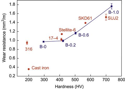
Wear properties have been studied from the early stage of developing HEAs, although data are still limited. Hsu et al. (2004) studied abrasion wear resistance of Al0.5BxCoCrCuFeNi (x=0, 0.2, 0.6, and 1) HEAs and found that the volume fraction of (Fe,Cr)-rich boride increases with B content. Figure 8.8 compares their wear resistance with that of typical wear-resistant alloys. The alloy with x=1 has better wear resistance than SUJ2 bearing steels. V and Ti additions to the same alloy were also reported (Chen et al., 2006a, 2006b). The wear resistance was rapidly improved with increasing the Ti content from 0.6 to 1.0 and reached a maximum at x=1.0 followed by gradual decrease at higher Ti contents. The optimum is due to the formation of CoCr-like phase between x=0.8 and 1.0. The wear resistance increases by around 20% as the content of V increases from x=0.6 to 1.2 and levels off beyond x=1.2. This improvement is mainly due to the formation of a very hard σ phase.
Tong et al. (2005a) reported the abrasion wear resistance of AlxCoCrCuFeNi (x=0.5, 1.0, 2.0). They found that Al0.5 alloy having a FCC structure and a hardness of 223 HV displays very high wear resistance close to that of SKD-61 with a hardness of 567 HV. Al1.0 alloy and Al2.0 alloy do not have better wear resistance even though their hardness values are around 410 and 570 HV, respectively. The excellent wear resistance of Al0.5 alloy is consistent with its high work hardening and ductility, which causes surface to be hardened by deformation during abrasion. Tsai et al. (2009b) had verified by TEM analysis that the large work hardening and ductility of Al0.5 alloy are related to the formation of nanotwins due to its low SFE. The other two BCC phase-containing alloys with higher Al contents show wear resistance no better than Al0.5 alloy because their BCC phase has a hardness of only around 600 HV and is brittle by nature.
Chuang et al. (2011) reported excellent adhesion wear resistance of Al0.2Co1.5CrFeNi1.5Ti HEA, which has a hardness of 717 HV and a resistance 3.6 times that of SUJ2 (AISI 52100) with similar hardness. In addition, the HEA also displays a wear resistance twice that of high-speed tool steel SKH51 (AISI M2) with a hardness of 870 HV. They demonstrated that this outstanding performance is due to its superior oxidation resistance and remarkable hot hardness over that of comparable steels because the contact temperature at the pin-disk interface can be as high as 800°C.
Plasma nitriding at 525°C for 45 h under a gas mixture of 25%N2+75%H2 has been applied to improve abrasive wear resistance of HEAs (Tang et al., 2009, 2010). For example, Al0.3CrFe1.5MnNi0.5 alloys after different processing routes can be well nitrided, with a thickness of around 80 μm, to attain a peak hardness level around 1300 HV near the surface. The main nitride phases in the surface layer are CrN, AlN, and (Mn,Fe)4N. Nitrided Al0.3CrFe1.5MnNi0.5 alloys have much better wear resistance than unnitrided ones by 49 to 80 times and also better than that of conventional nitrided alloys, nitriding steel SACM-645 (AISI 7140), 316 stainless steel, and hot-mold steel SKD-61 (AISI H13) by 22 to 55 times. The superiority is because the nitrided HEA alloys possess a much thicker highly hardened layer than the conventional alloys.
8.4 Electrochemical Properties
In principle, the overall composition and microstructure of an alloy affect its corrosion resistance in different corrosive environments. Some HEAs have demonstrated excellent performance in both H2SO4 and NaCl solutions. Similar to conventional alloys, it is interesting to note that Cr, Ni, Co, Ti in HEAs enhance corrosion resistance in acid solutions, Mo tends to inhibit pitting corrosion, whereas Al and Mn display a negative effect. However, detailed investigation of the mechanisms is still required.
Figure 8.9 plots the potentiodynamic polarization curves of AlCoCrCu0.5FeNiSi alloy and 304 stainless steel in 0.1 M NaCl solution (Chen et al., 2005d, 2005b, 2005c, 2006c). In this solution, the HEA displays passivation behavior. Corrosion potential is higher than that of 304 steel, and corrosion current density is smaller than that of 304 stainless steel. Similar superiority is observed in 1 M NaCl solution. On the other hand, Table 8.1 gives the average corrosion rates (in mpy) obtained from polarization curves and immersion tests of as-cast CoCrCuxFeNi alloy (x=0, 0.5, 1) in 3.5% NaCl solution (Hsu et al., 2005). These data demonstrate that Cu addition is detrimental to pitting resistance. However, CoCrFeNi is still better than 304L stainless steel in pitting resistance.

Table 8.1
Average Corrosion Rate of CoCrCuxFeNi HEAs Obtained from Immersion Test and Polarization Curve in 3.5% NaCl Solution (Hsu et al., 2005)
| CoCrFeNi | CoCrCu0.5FeNi | CoCrCuFeNi | |
| Immersion test | 7.62×10⁻⁴ | 8.89×10⁻³ | 1.14×10⁻² |
| Polarization test | 3.31×10⁻⁴ | 7.46×10⁻³ | 1.37×10⁻² |

Potentiodynamic polarization studies of as-cast Al0.5CoCrCuFeNi alloy and 304 stainless steel in 1N H2SO4 solution (Lee et al., 2007) indicate that corrosion potential of HEA is higher than that of 304 stainless steel and corrosion current density is smaller than 304 stainless steel, indicating general corrosion is better than that of 304 stainless steel. However, it is clear that HEA has poorer passivation behavior. This can be attributed to the formation of Cu-rich ID phase which provides local galvanic cell to enhance pitting. Similar studies have been carried out on as-cast AlxCrFe1.5MnNi0.5 alloys in 0.5M H2SO4 solution (Lee et al., 2008b). They all exhibit good passivation regions. However, Al-free alloy has better corrosion resistance than Al-containing alloys because it has smaller passive current density and corrosion current density.
The electrochemical characteristics of Co1.5CrFeMoxNi1.5Ti0.5 (x=0, 0.1, 0.5, 0.8) alloys in solutions of 0.5M H2SO4 and 1 M NaCl have been studied (Chou et al., 2010a, 2010b, 2011). The potentiodynamic polarization curves of the HEAs in acidic solution exhibit active–passive corrosion behavior, yielding an extensive passive region. This indicates that Mo-free alloy is more resistant to general corrosion than that of the Mo-containing alloys in acidic environments. On the other hand, the cyclic polarization curves demonstrate that the Mo-free alloy is susceptible to pitting corrosion in 1 M NaCl solution, but Mo-containing alloys are not and also their passive films can be repaired by themselves.
8.5 Oxidation Behavior
In conventional alloys, oxidation resistance could be largely improved by adding suitable amounts of Al, Cr, and Si, because these elements could form dense and stable oxide layer on the surface at high temperatures (Sims and Hagel, 1972). By the same principle, many HEAs containing such elements generally display improved oxidation resistance. Thus, AlCoCrFeNi and AlCoCrFeMoNi HEAs often show good oxidation resistance up to 1100°C. AlCrFeMnNi alloy often has less oxidation resistance when Mn content is higher.
The oxidation resistance of refractory HEAs is quite poor because refractory elements such as Ti, Zr, and Hf have a strong affinity to oxygen but their oxides are not adherent by nature. In addition, oxide of V has a low melting point, and those of Mo and W have low boiling points. Senkov et al. (2012b) investigated the isothermal oxidation behavior of a refractory HEA CrMo0.5NbTa0.5TiZr during heating at 1273 K for 100 h in flowing air. Continuous weight gain occurred during oxidation, and the time dependence of the weight gain per unit surface area can be described by a parabolic dependence with the time exponent n=0.6. The alloy has a better combination of mechanical properties and oxidation resistance than commercial Nb alloys and earlier reported developmental Nb–Si–Al–Ti and Nb–Si–Mo alloys. Liu et al. (2014) studied four types of new refractory HEAs Al0.5CrMoNbTi (H–Ti), Al0.5CrMoNbV (H–V), Al0.5CrMoNbTiV (H–TiV), and Al0.5CrMoNbSi0.3TiV (H–TiVSi0.3). As expected, these refractory HEAs mainly consist of a simple BCC solid solution due to the high mixing entropy effect. But, the oxidation kinetics of all the refractory HEAs at 1300°C follows a linear behavior although there are some differences in oxidation rate among them. The oxidation resistance of the HEAs is significantly improved with Ti and Si addition, but reduced with V addition. Thus, improvement of oxidation resistance of refractory HEAs is still a very important issue for high temperature applications as compared to superalloys. In another study, Zhu et al. (2014) prepared fully dense Ti(C,N) cermets with AlCoCrFeNi HEA as a binder. They have demonstrated that the HEA binder gives much better oxidation resistance than the conventional Ni/Co binder (Figure 8.10).

Two alloy powders of AlCoCrFeMo0.5NiSiTi and AlCrFeMo0.5NiSiTi have been plasma sprayed on alumina substrate as coating layer around 160 µm in thickness (Huang et al., 2004). Their oxidation resistance was measured by weight gain after exposure to oxygen at high temperatures. From the atmospheric oxidation experiment, both coating layers possessed good oxidation resistance at 1000°C, and even up to 1100°C since their weight gains in the formation of oxides approached a constant level after about 50 h as shown in Figure 8.11. Passive oxide layers were formed and protected the underlying materials as evident from EDS mapping. The top protective layer was of Ti oxide and next layer was of Cr oxide. Since Ti oxide could not provide a good protection, it is believed that the protection to oxidation is mainly attributable to Cr.
