

Expanding the solution to consumers
This chapter describes the second phase of the mobile luggage tracking solution for Airline Company A, which expands the application to the airline’s primary consumers, its passengers. It builds upon the information provided in Chapter 4, “Creating and deploying the mobile solution” on page 59, where an initial application was built for use by airline customer service representatives, and introduces these new features:
•Integration with IBM WebSphere eXtreme Scale
•Integration with the IBM DataPower XG45 appliance
•Integration with WebSphere Cast Iron
The following topics are covered:
The chapter includes snippets of source code used in the mobile solution and assumes that readers understand basic application development principles. It also assumes knowledge of Eclipse and its functions. The iOS-specific sections assumes knowledge of the Xcode IDE.
*********************************************************************************
IBM DOES NOT WARRANT OR REPRESENT THAT THE CODE PROVIDED IS COMPLETE OR UP-TO-DATE. IBM DOES NOT WARRANT, REPRESENT OR IMPLY RELIABILITY, SERVICEABILITY OR FUNCTION OF THE CODE. IBM IS UNDER NO OBLIGATION TO UPDATE CONTENT NOR PROVIDE FURTHER SUPPORT.
ALL CODE IS PROVIDED "AS IS," WITH NO WARRANTIES OR GUARANTEES WHATSOEVER. IBM EXPRESSLY DISCLAIMS TO THE FULLEST EXTENT PERMITTED BY LAW ALL EXPRESS, IMPLIED, STATUTORY AND OTHER WARRANTIES, GUARANTEES, OR REPRESENTATIONS, INCLUDING, WITHOUT LIMITATION, THE WARRANTIES OF MERCHANTABILITY, FITNESS FOR A PARTICULAR PURPOSE, AND NON-INFRINGEMENT OF PROPRIETARY AND INTELLECTUAL PROPERTY RIGHTS. YOU UNDERSTAND AND AGREE THAT YOU USE THESE MATERIALS, INFORMATION, PRODUCTS, SOFTWARE, PROGRAMS, AND SERVICES, AT YOUR OWN DISCRETION AND RISK AND THAT YOU WILL BE SOLELY RESPONSIBLE FOR ANY DAMAGES THAT MAY RESULT, INCLUDING LOSS OF DATA OR DAMAGE TO YOUR COMPUTER SYSTEM.
IN NO EVENT WILL IBM BE LIABLE TO ANY PARTY FOR ANY DIRECT, INDIRECT, INCIDENTAL, SPECIAL, EXEMPLARY OR CONSEQUENTIAL DAMAGES OF ANY TYPE WHATSOEVER RELATED TO OR ARISING FROM USE OF THE CODE FOUND HEREIN, WITHOUT LIMITATION, ANY LOST PROFITS, BUSINESS INTERRUPTION, LOST SAVINGS, LOSS OF PROGRAMS OR OTHER DATA, EVEN IF IBM IS EXPRESSLY ADVISED OF THE POSSIBILITY OF SUCH DAMAGES. THIS EXCLUSION AND WAIVER OF LIABILITY APPLIES TO ALL CAUSES OF ACTION, WHETHER BASED ON CONTRACT, WARRANTY, TORT OR ANY OTHER LEGAL THEORIES.
THIRD PARTY SOFTWARE IS LICENSED AND DISTRIBUTED TO YOU BY THE THIRD PARTY DISTRIBUTORS AND/OR RESPECTIVE COPYRIGHT AND OTHER RIGHT HOLDERS UNDER THEIR TERMS AND CONDITIONS. IBM MAKES NO EXPRESS OR IMPLIED WARRANTIES OR REPRESENTATIONS WITH RESPECT TO SUCH SOFTWARE AND PROVIDES NO INDEMNITY FOR SUCH SOFTWARE. IBM GRANTS NO EXPRESS OR IMPLIED PATENT OR OTHER LICENSE WITH RESPECT TO AND IS NOT LIABLE FOR ANY DAMAGES ARISING OUT OF THE USE OF SUCH SOFTWARE.
5.1 Breaking down the new scenario
Because of positive feedback from customers and CSRs following the release of the initial LuggageTracker application, Airline Company A has decided to proceed with the next phase of its mobile solution roadmap. In this phase, a second application called MyLuggage will be created to give airline passengers access to the same kind of luggage-tracking information that CSRs can get using LuggageTracker.
In contrast to LuggageTracker, the first version of MyLuggage will only support Android devices.
5.1.1 High-level use case
The high-level use case for the internal luggage tracking solution (described in 4.1.1, “High-level use case” on page 61) also applies to the new, business-to-consumer application, which will provide a similar set of capabilities but to a different set of users. In its first release, MyLuggage will support users who have registered to use the airline’s website and therefore already have a username and password stored in the airline’s back-end systems. These same credentials will be required to access the new mobile application.
5.1.2 Agile breakdown and design
Using agile methodologies, the high-level use case is broken down into four main scenarios or user stories:
•Install: As a passenger with a supported mobile device, I need to find MyLuggage in my device vendor’s application store and then install it using the mechanism provided.
•Login: As a registered user of the airline’s website, I need to launch the new MyLuggage application I just installed and then log in using my existing credentials.
•Locate: As a logged-in user, I need to locate my checked bag when it does not arrive at my destination as expected.
•Deliver: As a registered user with a delayed bag that must be delivered to me later, I need to update my baggage record with a delivery address, either by entering it manually or by selecting it from a map.
For each of these user stories, the airline’s mobile development and design teams completed a storyboard to list the specific interactions between the user, the mobile application, and the airline’s back-end services. These storyboard mock-ups or flows are shown in the following subsections.
From a development perspective, each story is broken down into tasks (see 5.1.3, “Solution components” on page 211) and each task is assigned to appropriate IT staff (see 5.1.5, “New tasks to implement the customer solution” on page 214). This task breakdown also involves completing the low-level application designs and expanding the airline’s mobile solution component model to meet the needs of the new application.
Install flow
The storyboard mock-up of the Install user story is shown in Figure 5-1. It details the initial installation of the application on the mobile device and is a “one-time story” in that the user installs the application only once.
The steps within the Install flow are as follows:
1. A mobile device user searches the device vendor’s application store for the MyLuggage application.
2. The user clicks Install to download and install the application on their device.
After the application is installed, it can be started using the application icon on the mobile device screen.

Figure 5-1 Storyboard of Install user story
Login flow
The storyboard mock-up of the Login user story is shown in Figure 5-2. It assumes that the Install user story has been completed.
The steps in the Login flow are as follows:
1. The user starts MyLuggage by clicking its icon on the mobile device screen.
2. A login dialog prompts for authentication information. The user provides the same username and password that the user previously created to use the airline’s website.
3. The user’s credentials are authenticated against the airline’s back-end user registry.
Upon a successful login, the MyLuggage home screen is displayed with these options:
•Scan Bar Code
•Retrieve Information
•Logout

Figure 5-2 Storyboard of Login user story
Locate flow
The storyboard mock-up of the Locate user story is shown in Figure 5-3. It assumes that the Login user story has been completed.
The steps in the Locate flow are as follows:
1. The user clicks Scan Bar Code and points the mobile device’s camera at their luggage receipt.
2. The application scans the bar code on the luggage receipt and displays the luggage identifier number on the device screen. If scanning fails, the user uses the device keyboard to manually enter the luggage identifier number into the application interface.
3. With the luggage identifier information successfully scanned or entered, the user clicks Retrieve Information.
4. Information about the bag is retrieved from the airline’s back-end systems, specifically, the Luggage Tracking Information System (LTIS), as follows:
– Owner’s name
– Current luggage status (such as Delayed or On-time)
– Current, next, and final destination
– Date of last status update
– Comments previously entered by the passenger (if any)

Figure 5-3 Storyboard of Locate user story
Deliver flow
The storyboard mock-up of the Deliver user story is shown in Figure 5-4. It assumes that the Locate user story has been completed and that the passenger’s delivery address for delayed bags must be updated.
The steps in the Deliver flow are as follows:
1. The user clicks Change Delivery Address to display a screen in which to enter a preferred delivery address, phone number, and comments.
2. The user enters the delivery address with one of two methods:
– By touching the appropriate text field and then typing the address using the device keyboard
– By clicking Map to view a map on which they can designate the address by touching its location on the display
3. The user enters a phone number and adds any comments, such as the a preferred delivery time, into the Comments field.
4. The user clicks Save and return to save the information in the LTIS and redisplay the Luggage information screen.
The LTIS record for the bag is now updated and can be used by the delivery service assigned to deliver late-arriving bags to passengers.

Figure 5-4 Storyboard of Deliver user story
5.1.3 Solution components
The airline’s mobile luggage tracking solutions, both the internal application and the new customer-facing application, are supported by the same component model. The original model for LuggageTracker contained three layers (see in 4.1.3, “Components of mobile luggage tracking solution” on page 65). Now, however, a fourth layer must be added for a secure reverse proxy server to handle user authentication. The secure reverse proxy server handles the authentication that was done by the authentication adapter in the internal application and the new layer for it exists between the mobile application layer and the mobile middleware layer.
Within each layer of the model is a set of core components, as shown in Figure 5-5. In the figure, the components with dashed borders are components of IBM Worklight Server; those with double-line borders are custom components written by the airline’s IT department.

Figure 5-5 Component model including new, passenger-facing application
To integrate the map-based address feature, the updated component model also includes a new native map component in the mobile application layer and a Map services adapter in the mobile middleware layer.
5.1.4 Expanding the topology
The MyLuggage application offers the same functions that are available to CSRs using LuggageTracker. Yet expanding the user base to include passengers complicates certain aspects of the solution topology, which must be expanded to meet these additional needs:
•Authentication and authorization of passengers through the use of existing back-end systems and registration data
•Minimization of third-party costs for services such as retrieving lists of hotels that are near to a specific geographic location.
•Integration with device-based location services, such as the mapping tools that will be used to designate a passenger’s preferred delivery location
To reduce development and maintenance costs, the new application must reuse the existing infrastructure and components of LuggageTracker when possible. The expanded topology for the passenger-facing application is shown in Figure 5-6.

Figure 5-6 Topology including new passenger-facing application
Authentication and authorization
In contrast to LuggageTracker, MyLuggage is a business-to-consumer application and therefore requires enhanced security mechanisms. Making the IBM Worklight server accessible to passenger-owned devices opens Airline Company A's IT infrastructure to inbound connections, which are potential security exposures if not controlled properly. Therefore, a secure gateway must be introduced to protect the existing IT infrastructure and restrict access to only those back-end services that are required by the new application. The IBM WebSphere DataPower XG45 appliance will provide firewall capabilities to protect internal systems. Using this appliance as the secure gateway creates what is essentially a self-contained security infrastructure for the new application.
Minimizing costs of third-party services
If third-party services, such as mapping services, will impose costs to the airline on a per-request basis, these costs can be minimized by caching the results of calls that are frequently repeated. Many users look up the same hotel, so caching this hotel information using IBM WebSphere eXtreme Scale not only reduces the per-request charges, it improves performance by replacing repeated calls to the external service with simpler, shorter calls to the internal caching system. The number of network hops decreases, which can result in reduced latency. And because WebSphere eXtreme Scale is a software solution, it requires no special hardware and can be installed on existing servers.
Integrating with location services
Ensuring that the passenger-supplied delivery address is valid requires additional data quality checks. The MyLuggage application uses the mobile device’s onboard location service to determine the passenger's current location and then retrieves a list of nearby hotels from a third-party service. By allowing the user to select one of these hotels, the accuracy of the delivery address is improved and the potential for errors based on manually input data is reduced. Because Airline Company A lacks its own database of worldwide hotel locations, the application accesses an external, third-party service using IBM WebSphere Cast Iron.
5.1.5 New tasks to implement the customer solution
The MyLuggage application will reuse many of the existing back-end services that were created for LuggageTracker, but will require a new user interface and security mechanism. The following list describes the tasks that are required for creating these new features by each involved member of the airline’s IT department:
•The new application user interface is created by a web mobile application developer using IBM Worklight Studio. To demonstrate how Worklight Studio supports other frameworks besides jQuery, the new mobile application is implemented using Dojo Mobile. This is done only to show the additional framework support available in Worklight Studio; there is no advantage in using Dojo Mobile instead of jQuery in this scenario.
•To support the selection of an address using device-specific mapping tools requires collaboration by these individuals:
– An integration developer uses IBM WebSphere Cast Iron to gather hotel information from a third-party service.
– The list of hotels from which the passenger can select is displayed on an interactive map using native device functionality. A native mobile application developer creates the native map page and the function to display the nearby hotels.
– A mobile server developer adds caching of the third-party hotel information using WebSphere eXtreme Scale.
•To add the required security mechanism, a system administrator integrates IBM Worklight Server with an IBM WebSphere DataPower XG45 appliance to connect the application with the existing security infrastructure and credentials database.
The remaining sections in this chapter explain how Airline Company A implemented the new passenger-facing application and provide step-by-step instructions for accomplishing the required tasks. If you want to implement the end-to-end scenario, you must complete each section.
5.2 Changes to the environments
Several new hardware and software products must be added to Airline Company A’s pre-production environment. In addition, the development environment requires updates to allow the native mobile application developer to add the native map functionality to MyLuggage.
The following subsections explain the changes to the development and pre-production environments.
|
Important: For the work described in this chapter, use the same IBM Worklight Studio workspace that you used for Chapter 4, “Creating and deploying the mobile solution” on page 59. You can switch workspaces in Worklight Studio by selecting File → Switch Workspace and then selecting the desired workspace.
|
5.2.1 Updating the development environment
With the new features that will be included in MyLuggage, there are several additions to the development environment for native mobile application developers, web mobile application developers and mobile server developers.
Native mobile application developer
As part of the delivery address-related functions in the new MyLuggage application, which will be available only for Android devices, a native Google Map page will be displayed. To enable this display, the native mobile application developer must do these tasks:
•Obtain a Google Maps API Key
•Update the Worklight Studio development environment to add Google Play services
The Google Maps API Key and Google Play Services are used by the native mobile application developer in 5.4.2, “Developing the native map page” on page 264 when the native map function is created.
Obtaining a Google Maps API key
The Google Maps API key is provided by Google and enables you to monitor your application's Maps API usage, and ensures that Google can contact you about your application if necessary. There are usage limits for the free key and if you exceed this quota, you must purchase additional quota from Google. To request a key, you must supply the package name of the Android application (com.AirlineShellComponentTest in this scenario) and the SHA-1 key of your signing certificate.
For details about obtaining a Google Maps API Key and retrieving the SHA-1 key of your certificate, see the Google Developers website at this address:
Adding Google Play services
To add the Google Play services library project to IBM Worklight Studio, install the Google Play services SDK with Android SDK Manager as follows:
1. Start IBM Worklight Studio using the same workspace that was used in Chapter 4, “Creating and deploying the mobile solution” on page 59.
2. Click Window → Android SDK Manager to display Android SDK Manager.
3. Deselect any updates for installed packages, if any of them are pre-selected.

Figure 5-7 Selecting Google Play services from Android SDK Manager
5. Click Install 1 package.
6. Read and accept the software license information and then click Install. As the Google Play services are downloaded and installed, you can follow the progress at the bottom of the dialog.
7. When installation completes, close Android SDK Manager.
Now that Google Play services are available for use in Worklight Studio, you must import the Google Play services library project into your workspace:
1. In Worklight Studio, click File → Import.
2. In the Import wizard, expand the android folder and select Existing Android Code Into Workspace, as shown in Figure 5-8, and then click Next.

Figure 5-8 Selecting to import existing Android code into the workspace
3. The Import Projects page of the wizard is displayed (Figure 5-9 on page 218). Click Browse to display the Browse For Folder dialog and locate the directory of the Google Play services library project (where <sdk_path> is the path for the Android SDK):
<sdk_path>/extras/google/google_play_services/libproject
Select the libproject directory and click OK.
|
HINT: If you do not know what to use for <sdk_path>, open Android SDK Manager and you will see the SDK Path listed at the top just below the menu bar.
|

Figure 5-9 Copying the Google Play Services project into the workspace
4. The directory of your google-play-services_lib project is now in the Root Directory field of Import Projects page. Ensure that the check box next to google-play-services_lib in the Project To Import column of the table checked, select the Copy projects into workspace check box and then click Finish.
You now have a new project in Project Explorer called google-play-services_lib.
|
Important: An Android application using the Google Play services library project can be tested only on a real device and not with the Android emulator. For information about this limitation, see the Google Developers Setup documentation for Google Play Services:
|
For further information regarding the use of Google Maps in an Android-based mobile application, see the Google Developers documentation:
Web mobile application developer
The security mechanism for MyLuggage will use the IBM WebSphere DataPower XG45 appliance and its use in the mobile application requires a base 64 encoding package. Therefore, the mobile application developers must add the selected package to their development environment.
Adding a base 64 encoding package
The IBM DataPower XG45 appliance expects the HTTP authorization header to be encoded to a base 64 file format.
To encode and decode the authorization header, the client-side authentication uses a third-party JavaScript library. Various base 64 encoding and decoding libraries can be used. For the purpose of this book, the authors used a JavaScript library from webtoolkit, called Javascript base64, available at this address:
To use the webtoolkit JavaScript base64 library in the development environment, copy the webtoolkit.base64.js file into the apps/common/js folder of the LuggageTrackerDojo application, naming it base64.js. If multiple developers are collaborating to develop the application, only one developer needs to add this file into the source code repository.
Mobile server developers
Caching functionality is being added to the adapters using WebSphere eXtreme Scale. As part of this function, the development environment must be updated with the following items:
•A Java-based JavaScript implementation
•The WebSphere eXtreme Scale client
Adding a Java-based JavaScript implementation
The hotel adapter that will be created for the new mapping function will use a third-party Java-based JavaScript implementation to provide scripting capabilities to the server-side caching classes.
For this scenario, the Mozilla Rhino third-party library is used to handle JavaScript objects that sent to and from Java classes. The Mozilla Rhino project is available in most Eclipse installations. To use it, copy a js.jar file, such as the one from your Worklight Studio installation, into the server/lib folder of the AirlineAdapterProject project. If multiple developers are collaborating to develop the application, only one developer needs to add this file into the source code repository.
Adding the WebSphere eXtreme Scale client
The hotel adapter will be updated to cache the hotel information that it obtains from the third-party service using WebSphere eXtreme Scale. To develop and test the caching functions, the WebSphere eXtreme Scale client API JAR file needs to be added to their development environment.
For this scenario, copy the WebSphere eXtreme Scale client API JAR file named osclient.jar (located in the <wxs_install_dir>/ObjectGrid/lib directory of the WebSphere eXtreme Scale installation) into the server/lib folder of the AirlineAdapterProject project in Worklight Studio. If multiple developers are collaborating to develop the application, only one developer needs to add this file into the source code repository.
|
Troubleshooting: At the time of writing, the authors found a conflict in the OSGi framework in which the WebSphere eXtreme Scale client API jar (ogclient.jar) cannot be added, as-is, to IBM Worklight Server. To resolve this conflict, extract the contents of the jar into a temporary location, remove the osgi folder, and then re-package the jar file.
|
5.2.2 Changes to the pre-production environment
To support the new features in MyLuggage, the pre-production environment must be expanded to include these tasks:
•Installing and configuring WebSphere eXtreme Scale for caching
•Installing and configuring IBM WebSphere Cast Iron
•Configuring the IBM DataPower XG45 appliance
Installing and configuring WebSphere eXtreme Scale
IBM WebSphere eXtreme Scale is the caching solution used for Airline Company A’s business-to-consumer application. If you do not already have WebSphere eXtreme Scale installed, see 6.6, “Installing IBM WebSphere eXtreme Scale” on page 319 for installation details.
This scenario uses a simple, single-grid configuration that is included in the Getting Started sample application. This sample application is part of the default product installation and can be found on the server where IBM WebSphere eXtreme Scale is installed in the following directory (<wxs_install_root> is the directory where the product was installed):
<wxs_install_root>/ObjectGrid/gettingstarted
This scenario uses the configuration from the objectgrid.xml file in the <wxs_install_root>/ObjectGrid/gettingstarted/xml directory. This file defines a single grid, named Grid, and two maps, named Map1 and Map2. No additional changes are necessary in this scenario.
To start the grid that will be used in this scenario, use the following steps:
1. Open a terminal session on the IBM WebSphere eXtreme Scale server, using an ID and password for a privileged user.
2. Change to the <wxs_install_root>/ObjectGrid/gettingstarted directory.
3. Start a catalog services process by running the ./runcat.sh command.
4. Open another command window and change to the same gettingstarted directory.
5. Run a container service instance by running the ./runcontainer.sh server0 command.
The catalog and container services are now running and able to process caching requests.
For additional information about this sample, see the GETTINGSTARTED_README.html file located in the <wxs_install_root>/ObjectGrid/gettingstarted directory.
Installing and configuring WebSphere Cast Iron
In this scenario, IBM WebSphere Cast Iron is used for retrieving hotel information from a third-party web service that takes specified a geographic location and returns a list of nearby hotels. This is used in the MyLuggage application to help users enter the address of a hotel for baggage delivery.
To install and configure WebSphere Cast Iron, several tasks must be completed:
•Install WebSphere Cast Iron
•Register for the third-party services
•Create the Cast Iron orchestration to retrieve the information from the third-party service
Installing WebSphere Cast Iron
To install and configure WebSphere Cast Iron for this scenario, see 6.5, “Installing IBM WebSphere Cast Iron” on page 315.
Registering for the third-party services
In this scenario, the Nokia Places API is used to retrieve hotel information and show how a solution can use third-party service providers. For further information about Nokia HERE and the Nokia Places API, see the documentation at this address:
To use the Nokia Places API, you must register with Nokia and receive credentials. These credentials, called an App Token, consist of an application identifier (app_id) and an application code (app_code). To register and receive your credentials, see the information at this address:
Creating the orchestration
The step-by-step creation of the Cast Iron orchestration for retrieving the hotel information will not be covered in detail here. Instead, the exported WebSphere Cast Iron project (NokiaHere.par) and the project source code (NokiaHere.zip) are provided as additional material for this book. Only the exported project file is required.
After you download the exported project file and obtain the needed credentials from Nokia, deploy the project as follows:
1. Start the WebSphere Cast Iron web management console as shown in Figure 5-10, in a browser using the following address (where <castiron_admin_ip_address> is the admin IP address for your Cast Iron installation):
https://<castiron_admin_ip_address>/login

Figure 5-10 Logging into the WebSphere Cast Iron web management console
2. Log in as admin using the proper admin password (by default, it is !n0r1t5@C).
3. In the navigation pane, click Repository to go to the repository view so you can upload a new project, as shown in Figure 5-11.

Figure 5-11 Changing to the Repository view
4. Click Upload Project to display the Upload Project Configuration dialog,
5. Click Browse and select the WebSphere Cast Iron project file (NokiaHere.par) that you downloaded previously. The file name is displayed in the Upload Project configuration dialog, shown in Figure 5-12.

Figure 5-12 Uploading the project file
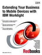
6. Click Upload. When the upload completes, the NokiaHere project is listed in the console as Undeployed, as shown in Figure 5-13.
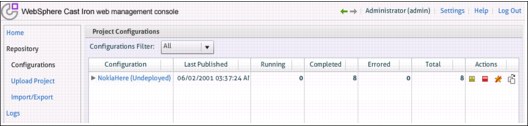
Figure 5-13 Uploaded configuration shown as undeployed
7. Switch to the detailed project view, shown in Figure 5-14, by clicking on the project name in the Configuration column.

Figure 5-14 Cast Iron project details
8. Click Edit in the Properties section. In the Edit Configuration Properties dialog, enter your Nokia Here credentials in the Value column, using your app_id for the appIdentifier property and your app_code for the appToken property.
9. Click Save to return to the detailed project view.
10. Start the project by clicking the Play symbol that is located beside the Status field in the Summary section at the top of the screen. The status changes to Running after the project is deployed, as shown in Figure 5-15.

Figure 5-15 Project displayed as running
11. . Verify that the map service is working by invoking the following statement from a web browser, replacing <cast_iron_data_ipaddress> with the IP address of the data network of your virtual appliance and <latitude> and <longitude> with the latitude and longitude of the location for which you want to find nearby hotels:
http://<cast_iron_data_ipaddress>/map?q=hotel&at=<latitude>,<longitude>
For example, to search for hotels near Mainz, Germany, the URL is as follows:
http://<cast_iron_data_ipaddress>/map?q=hotel&at=49.9945,8.2672
With these steps completed, the WebSphere Cast Iron orchestration to retrieve the hotel information is deployed and tested, and can now be used by the application.
Configuring the IBM DataPower XG45 appliance
The IBM WebSphere DataPower Service Gateway XG45 appliance is used to provide security for MyLuggage. In contrast to LuggageTracker, the new application will be used by airline passengers outside of the corporate network. The XG45 appliance will function as a network security gateway, ensuring only authorized access from the mobile application to the internal corporate systems. Figure 5-16 illustrates the authentication flow.

Figure 5-16 Authentication flow with the DataPower XG45 appliance
As a user logs in to the mobile application, the user credentials (user name and password) are sent to the XG45 appliance, which is located in the perimeter network (DMZ). The appliance authenticates incoming service requests against a user registry, which in this case contains airline customers (passengers) who have previously registered to use the company website. When a user is authenticated, a notice of a successful authentication is returned to the mobile application. If the user credentials are not valid, a notice of an authentication failure is returned to the mobile application.
Configuring an XML firewall to authenticate users
Airline Company A created an XML firewall policy on the XG45 appliance to implement its security model.
To configure the XML firewall to authenticate against the user registry, complete the following steps on the XG45 appliance:
1. Log in to the XG45 appliance using your administrator ID and password.
2. In the Control Panel, click XML Firewall.
3. To create a new XML firewall, click Add Advanced.
4. On the General tab of the Configure XML Firewall page, set the following attributes (shown in the red boxes in Figure 5-17 on page 225):
– Firewall Name: PassengerFirewall
– Comments: This is the firewall for registered passengers
– Firewall Type: Static Backend (this creates a secure reverse proxy for Worklight Server)
– Port Number: <any unused port> (7878 is shown in this example)
– Remote Host: <your_worklight_server_address> (9.111.27.228 is shown in this example)
– Remote Port: <your_worklight_server_port> (9080 is shown in this example)
– Response and Request Type: non-XML

Figure 5-17 Configuring a new XML firewall on the XG45 appliance
5. Click the plus sign (+) beside the Processing Policy list to create a processing policy.
6. On the Configure XML Firewall Style Policy dialog, enter AuthenticateUser for the Policy Name and then click New Rule.
7. Change the rule name to authenticateUser and set the Rule Direction to Client to Server.
You notice that at first, the rule diagram contains a single Match action, as shown in Figure 5-18.

Figure 5-18 Creating the policy and first rule
8. Double-click the match rule icon (which is highlighted in yellow in the display) to display the Configure a Match Action dialog.
9. Click the plus sign (+) beside the Matching Rule property, as shown in Figure 5-19, to create a new matching rule.

Figure 5-19 Creating the matching rule
10. The Configure Matching Rule dialog opens (Figure 5-20). Enter authenticateUser_MatchingRule for the name, and then click the Matching Rule link.

Figure 5-20 Configuring the matching rule
11. The Matching Rule table is added to the dialog. Click Add to configure the matching rule.
12. The Edit Matching Rule dialog opens (Figure 5-21). Select URL from the Matching Type list, enter /authenticateUser for the URL match, and click Apply.

Figure 5-21 Editing the matching rule
13. The Configure Matching Rule dialog is redisplayed showing the URL matching rule that you just created in the table. Click Apply.
14. The Configure a Match Action dialog is redisplayed. Click Done.
With these steps completed, the Configure XML Firewall Style Policy dialog is redisplayed (Figure 5-22 on page 228).
The next part of the process involves adding an authorization, authentication, and auditing (AAA) action to the authenticateUser rule. To do this:
1. Select the AAA action icon. Drag it to the rule line, and place it to the right of the match action icon, as shown in Figure 5-22.

Figure 5-22 Adding the AAA action to the policy
2. Double-click the AAA action icon to open the Configure AAA Action dialog (Figure 5-23,).

Figure 5-23 Configuring the AAA action
3. Select INPUT from the list beside the Input field (which displays INPUT in the text field) and select OUTPUT from the list beside the Output field (which displays OUTPUT in the text field).
4. Click the plus sign (+) beside the AAA Policy list to create a new AAA policy.
5. The Configure an Access Control Policy dialog opens (Figure 5-24). Enter authenticate-user for the AAA Policy Name and then click Create.
6. Select HTTP Authentication Header to extract the user’s identity from the incoming request, and then click Next.

Figure 5-24 Configuring the policy to extract the user identity from the request header
7. The next step is to configure how to authenticate a specific user. The user registry in this scenario is an LDAP registry, so select the Bind to Specified LDAP Server method from the list, as shown in Figure 5-25, and then enter the directory service information for an LDAP connection in the fields at the bottom of the screen. If you use a different authentication method, select it from the list and enter the information as required.
Figure 5-25 Defining the LDAP connection to authenticate the users
8. Click Next.
9. On the Configure an Access Control Policy page (Figure 5-26), select URL sent by Client. The completed post-processing options should look similar to what is shown in the figure.

Figure 5-26 Defining the resource identification method
10. Proceed through the wizard using the Next button to accept the default values.
11. In the post-processing step of the wizard, ensure all the values are set to off.
12. Click Commit and then Done to complete the configuration.
13. Save the configuration changes.
The XML firewall is now configured to authenticate customers against a customer user registry and is ready to be tested.
Testing the XML Firewall configuration
The configuration now needs to be tested. Airline Company A tested the configuration using cURL, a command-line tool you can use to send or retrieve files using URL syntax. The cURL tool is available at no charge from the cURL website:
To invoke cURL for this scenario, use the following command, where <username:password> is a set of valid credentials that exist in the airline passenger user registry and <dp_address:port> is the appliance’s IP address and the XML firewall port number (7878 in this example).
curl -v -u <username:password> http://<dp_address:port>:7878/authenticateUser
Figure 5-27 shows the result of the cURL test of the AAA policy to authenticate user login requests against the user registry.

Figure 5-27 Testing of the AAA policy to authenticate the user using cURL
The XML firewall is now tested and is ready to authenticate users for MyLuggage.
5.3 Changes to the back-end services
Two changes are required to the back-end services to support the new functions in MyLuggage.
The new application will use the airline’s existing back-end services to obtain the current status of a passenger’s bag and record the passenger’s preferred delivery address. But when that delivery address will be a hotel, the airline wants to allow passengers to locate their hotel on a map instead of having to enter the specific address using the keyboard. Offering this feature requires that hotel information be obtained from a third-party mapping service. Obtaining the hotel information will be done using a new adapter.
The second change is to the existing authentication adapter. Although the authentication of user credentials for MyLuggage will be done using the DataPower appliance, Worklight Server still needs to get the user identity set after authentication is completed. This can be accomplished by adding another procedure to the existing adapter.
5.3.1 Creating the hotel adapter
The third-party mapping service will use IBM WebSphere Cast Iron as an integration broker, which is described in 5.3, “Changes to the back-end services” on page 232.
The hotel information that is obtained from the third-party service will be cached. There are several reasons to use caching:
•Invoking third-party services takes time, which can slow the application.
•Third-party services may charge on a per-request basis, which can add to the overall cost of the new solution.
•Only a limited number of airport locations are likely to be searched, and passengers will search for the same hotels repeatedly.
Costs can be reduced and response times improved by determining if specific hotel information is already cached before invoking the third-party service.
To satisfy these requirements, the server component developer must create a new IBM Worklight adapter, which will use IBM WebSphere Cast Iron to invoke the third-party service to obtain the hotel information. Caching capabilities are then added to cache the hotel information.
There are three stages to implementing the hotel information adapter:
•Creating the adapter
•Adding caching capabilities
•Testing the adapter
Creating the adapter
The hotel information Cast Iron adapter is part of the AirlineAdapterProject that also contains the adapters created in the previous chapter. To create the hotel information adapter, use the following steps:
1. Start IBM Worklight Studio if it is not already started.
2. Expand the AirlineAdapterProject project.
3. Right-click the adapters folder and create a new adapter by selecting File → New → Worklight Adapter.
4. In the New Worklight Adapter dialog, select Cast Iron Adapter from the Adapter type list, and enter MapAdapter for the Adapter name.
5. Click Finish to create the adapter. A new folder named MapAdapter is created and within it are several auto-generated files similar to the files that were generated when the previous adapters were created. You can delete the ci-filtered.xsl file because it is not used in this scenario.
6. The MapAdapter.xml file is automatically opened in the adapter editor. If this does not occur, open the file by right-clicking on the file and selecting Open With → Adapter Editor.
7. Switch to the Source tab if it is not shown.
8. In the XML source, find the <wl:adapter> tag block that was created when the file was auto-generated and replace it with the XML shown in Example 5-1 on page 234. When doing this, replace server_name and server_port with the server URL and port of your WebSphere Cast Iron server. This XML defines the method, getHotels, that will be called when the adapter is invoked.
Example 5-1 Replacement adapter tag block in MapAdapter.xml
<wl:adapter name="MapAdapter"
xmlns:xsi="http://www.w3.org/2001/XMLSchema-instance"
xmlns:wl="http://www.worklight.com/integration"
xmlns:http="http://www.worklight.com/integration/http"
xmlns:ci="http://www.worklight.com/integration/ci">
<displayName>MapAdapter</displayName>
<description>MapAdapter</description>
<connectivity>
<connectionPolicy xsi:type="http:HTTPConnectionPolicyType">
<protocol>http</protocol>
<domain>server_name</domain>
<port>server_port</port>
</connectionPolicy>
<loadConstraints maxConcurrentConnectionsPerNode="2" />
</connectivity>
<procedure name="getHotels"/>
</wl:adapter>
9. Save and close the MapAdapter.xml file.
The new function, getHotels, is implemented in the MapAdapter-impl.js file and is called from the adapter definition (see Example 5-1). To add this function, use the following steps:
1. Open the MapAdapter-impl.js file in Rich Page Editor.
2. Replace the auto-generated functions with the JavaScript shown in Example 5-2. The getHotels function implements the procedure defined in the adapter XML shown in the previous example.
The input parameters of the getHotels() function are the latitude and longitude coordinates to be used in the search for nearby hotels. The JavaScript creates the input variable that is passed to Worklight Server and used to invoke the Cast Iron service. The Cast Iron service is invoked using an HTTP GET request to the following URL:
http://<server>:<port>/map?q=hotel&at=<latitude>,<longitude>
Example 5-2 Adding the getHotels function
function getHotels(latitude, longitude){
var input = {
method : 'get',
appName : '/',
path : 'map?q=hotel&at='+latitude+','+longitude,
returnedContentType : 'json'
};
return WL.Server.invokeCastIron(input);
}
3. Save and close the MapAdapter-impl.js file.
The adapter is now able to call the third-party server to obtain hotel information. You can test it now, or wait until after the caching is added.
Adding caching capabilities
The adapter will integrate with WebSphere eXtreme Scale as a caching server to improve application response times. This caching approach assumes that hotel location information is generally static and that multiple customers will be searching for the same hotels.
Defining the cache key is critical to gaining the full benefit of caching. Exact longitude and latitude coordinates, if used as a key, would be too precise and therefore generate too few cache hits. So the user’s coordinates are rounded to two decimal places, which is unlikely to affect the customer but will result in much-improved hit rates and response times.
The tasks required to add caching to the MapAdapter are as follows:
•Creating the client-side caching classes
•Adding a new procedure in the adapter
•Creating the JavaScript function that calls the client-side caching classes
Creating the client-side caching classes
Airline Company A created the following three Java classes to handle the connection to the WebSphere eXtreme Scale server, data retrieval, and updating of the cached data:
•WLCache: converts the cache objects to and from JSON
•ConnectXS: acts as a client proxy for connecting to the caching server
•ExternalXS: an abstraction layer for the caching operations
The Java source for these files is in “WebSphere eXtreme Scale caching integration files” on page 356. Create these three Java files, compile them, and copy the class files into the server/java folder of the AirlineAdapterProject project. During compilation, you must add the osgi.jar and js.jar files (from the server/lib folder of the AirlineAdapterProject project) to your build path.
For more information about using WebSphere eXtreme Scale as a caching solution for IBM Worklight applications, see the eXtreme Scale caching with Worklight 5.0 developerWorks article:
Updating the adapter definition
To enable caching at the adapter level, add another procedure call to obtain the cached hotel information, use the following steps:
1. Open the MapAdapter.xml file in Rich Page Editor.
2. Go to the Source tab.
3. Add a new procedure called getCachedHotels beneath the getHotels procedure, as shown in bold in Example 5-3.
Example 5-3 Adding the getCachedHotels procedure to the adapter definition
<wl:adapter name="MapAdapter"
xmlns:xsi="http://www.w3.org/2001/XMLSchema-instance"
xmlns:wl="http://www.worklight.com/integration"
xmlns:http="http://www.worklight.com/integration/http"
xmlns:ci="http://www.worklight.com/integration/ci">
<displayName>MapAdapter</displayName>
<description>MapAdapter</description>
<connectivity>
<connectionPolicy xsi:type="http:HTTPConnectionPolicyType">
<protocol>http</protocol>
<domain>server_name</domain>
<port>server_port</port>
</connectionPolicy>
<loadConstraints maxConcurrentConnectionsPerNode="2" />
</connectivity>
<procedure name="getHotels"/>
<procedure name="getCachedHotels"/>
</wl:adapter>
4. Save and close the MapAdapter.xml file.
Creating the JavaScript function to cache the data
The new function, getCachedHotels, is implemented in the MapAdapter-impl.js file and is called from the adapter definition (see Example 5-3).
The function creates the cache key from the latitude and longitude coordinates passed in as parameters to the function call, and then uses the three client-side caching classes created in “Creating the client-side caching classes” on page 235 to add data to the cache and retrieve cached data when requested.
To create the new getCachedHotels function, use the following steps:
1. Open the MapAdapter-impl.js file in Rich Page Editor.
2. Add the getCachedHotels function, shown in Example 5-4 on page 237, beneath the getHotels function. The getCachedHotels function implements the new procedure defined in the adapter XML shown in the previous example and adds caching to the previous getHotels function (which is now not used but was not removed in this scenario).
The cache key is created first and contains the latitude and longitude coordinates rounded to two decimal places. When a new request is received, the WLCache class connects to the caching grid that was created in 5.2.2, “Changes to the pre-production environment” on page 220 to check for cached hotel information based on the rounded coordinates in the cache key. If the cache key exists, the cached value (the map of hotels located near the submitted coordinates) is returned in JSON format. If the cache key is not found, the Cast Iron adapter is called to get the necessary hotel information from the third-party source. The information that is retrieved is added to the cache and then returned to the application.
Example 5-4 Adding the caching function
function getCachedHotels(latitude, longitude) {
// Create the caching key
var inputKey = latitude.toFixed(2)+','+longitude.toFixed(2);
// Connect to eXtreme Scale
var wlCache = com.ibm.worklight.example.extremescale.WLCache("caching.server", 2809, "Grid", "Map1");
if (wlCache.getString(inputKey)) { //object exists, return cached value
return JSON.parse(wlCache.getString(inputKey));
}
else { // invoke Cast Iron to retrieve hotel information
var input = {
method : 'get',
appName : '/',
path : 'map?q=hotel&at='+inputKey,
returnedContentType : 'json'
};
var result = WL.Server.invokeCastIron(input);
if(result != null){ // adding new value to the cache
wlCache.putString(inputKey, JSON.stringify(result));
}
}
return result;
}
3. Save and close the MapAdapter-impl.js file.
The adapter is now updated to use WebSphere eXtreme Scale to cache the hotel information and can be tested.
Testing the adapter
The adapter is deployed and tested using the same procedures described in “Testing the adapter” on page 103, and using various longitude and latitude combinations.
5.3.2 Updating the authentication adapter
Even though mobile application authentication is handled by the DataPower XG45 appliance, the active user in IBM Worklight must still be set to the identity of the authenticated user. To minimize development and maintenance costs, the authentication adapter created in 4.7.2, “Creating the authentication adapter” on page 91, was updated to add a new procedure to set the active user instead of creating a new adapter.
There are three stages to updating the authentication adapter:
•Updating the adapter definition
•Creating the JavaScript function
•Testing the adapter
Updating the adapter definition
The existing authentication adapter, named LuggageTrackerAdapter, must be updated to add a new procedure, which will be invoked by the client-side authentication process after the actual user credential validation has been completed. This new procedure is used to set the active user in Worklight Server.
To add the new procedure, use the following steps:
1. Start IBM Worklight Studio if it is not already started.
2. Expand the AirlineAdapterProject project and then expand the adapters and LuggageTrackerAdapter folders.
3. Open the LuggageTrackerAdapter.xml file in Rich Page Editor.
4. Go to the Source tab.
5. Add a new procedure named setUserIdentity beneath the submitAuthentication procedure, as shown in bold in Example 5-5.
Example 5-5 Adding the setUserIdentity procedure to the LuggageTrackerAdapter definition
<wl:adapter name="LuggageTrackerAdapter"
xmlns:xsi="http://www.w3.org/2001/XMLSchema-instance"
xmlns:wl="http://www.worklight.com/integration"
xmlns:http="http://www.worklight.com/integration/http">
<displayName>LuggageTrackerAdapter</displayName>
<description>LuggageTrackerAdapter</description>
<connectivity>
<connectionPolicy xsi:type="http:HTTPConnectionPolicyType">
<protocol>http</protocol>
<domain>localhost</domain>
<port>8088</port>
</connectionPolicy>
<loadConstraints maxConcurrentConnectionsPerNode="2" />
</connectivity>
<procedure audit="true" name="submitAuthentication"/>
<procedure audit="true" name="setUserIdentity"/>
<procedure audit="true" name="onLogout"/>
</wl:adapter>
6. Save and close the LuggageTrackerAdapter.xml file.
Creating the JavaScript function
The new function, setUserIdentity, is implemented in the LuggageTrackerAdapter-impl.js file and is called from the adapter definition (see Example 5-5).
Follow these steps:
1. Open the LuggageTrackerAdapter-impl.js file in Rich Page Editor.
2. Add the JavaScript for the setUserIdentity function, shown in Example 5-6 on page 239, to the file beneath the submitAuthentication function.
Example 5-6 JavaScript for the setUserIdentity function
function setUserIdentity(username, password){
if (username){
WL.Logger.debug("setUserIdentity");
var userIdentity = {
userId: username,
displayName: username,
attributes: {
userType: "Passenger"
}
};
WL.Server.setActiveUser("LuggageTrackerRealm", userIdentity);
return {
isLoginSuccessful:true,
authRequired: false
};
}
WL.Server.setActiveUser("LuggageTrackerRealm", null);
return onAuthRequired(null, "Invalid login credentials");
}
3. Save and close the LuggageTrackerAdapter-impl.js file.
The adapter is now updated to set the active user within Worklight Server.
Testing the adapter
The adapter is deployed and tested using the same procedures described in “Testing the adapter” on page 103, using both valid and invalid credentials.
5.4 Creating the new mobile application
The new mobile application, MyLuggage, will have a completely new user interface created using Dojo Mobile instead of jQuery. The use of Dojo Mobile is intended only to show how to use it; there is no technical advantage to using one product instead of the other for development of this specific application.
The new customer-facing application will also incorporate a new security mechanism using the DataPower XG45 appliance (configured in “Configuring the IBM DataPower XG45 appliance” on page 224), and add a native map component to assist users in providing their delivery address.
5.4.1 Creating the user interface using Dojo
The MyLuggage application consists of four screens, each of which contains specific elements. These elements are almost identical to those in LuggageTracker, although minor differences exist. The screens and elements in the MyLuggage application are as follows:
•Login
– Text input field for User Name
– Text input field for Password
– Login button
•Luggage ID input
– Text input field for Luggage ID
– Scan Bar Code button
– Retrieve Information button
– Logout button
•Luggage information
– Text input field for Current Status
– Text input field for Owner Name
– Text input field for Current Location
– Text input field for Next Destination
– Text input field for Final Destination
– Text input field for Last Update
– Text area field for Comments
– Change Delivery Address button
– Close button
•Luggage delivery address
– Text input field for Luggage ID
– Text input field for Name
– Text input field for Address Line 1
– Map button
– Text input field for Address Line 2
– Text input field for City
– Text input field for State
– Text input field for Zip Code
– Text input field for Phone Number
– Text area field for Comments
– Save and return button
– Cancel button
For purposes of this book, detailed instructions are provided only for creating the Login and Luggage ID input screens using Dojo Mobile. Abbreviated instructions for creating the Luggage information and Luggage delivery address screens using Dojo Mobile are supplied at the conclusion of this section.
Creating the new hybrid application
The user interface for MyLuggage is created using Dojo Mobile in the same IBM Worklight Studio project (CompanyAirlines) that is used for the original LuggageTracker application. During the creation of the project (see “Creating the user interface project” on page 106), the hybrid application for LuggageTracker was created. Because MyLuggage will use the same project, a new hybrid application must be created for the new application.
Use the following steps:
1. Start IBM Worklight Studio if it is not already started.
2. Expand the CompanyAirlines project.
3. Right-click the apps folder and select New → Worklight Hybrid Application, as shown in Figure 5-28.

Figure 5-28 Creating a new Worklight Hybrid Application
4. In the dialog that is displayed, enter LuggageTrackerDojo in the Application name field and select the Add Dojo Toolkit check box, as shown in Figure 5-29.

Figure 5-29 Specifying the application name and adding the Dojo Toolkit
5. Click Finish. The CompanyAirlines project in Project Explorer now shows both applications, LuggageTracker and LuggageTrackerDojo (the MyLuggage application), as shown in Figure 5-30.

Figure 5-30 New hybrid application displayed in Project Explorer
The project name used within Worklight Studio is LuggageTrackerDojo but the display name should be MyLuggage. To change the display name of the application, use the following steps:
1. If it is not already open, double-click the application-descriptor.xml file in Project Explorer to open it in Application Descriptor Editor.
2. On the Design tab, change the Display name attribute from LuggageTrackerDojo to MyLuggage. Leave the ID attribute unchanged.
3. You may also change the Description by editing the Description attribute.
4. Save and close the application-descriptor.xml file.
Building the user interface screens
To create the user interface screens, you edit the mobile application main file, LuggageTrackerDojo.html, which was automatically generated when the LuggageTrackerDojo application was created. To open this file and prepare your Worklight Studio environment for creation of the various screens, use the following steps:
1. In Project Explorer, expand the CompanyAirlines project until the files in the LuggageTrackerDojo folder are visible.
2. Open the LuggageTrackerDojo.html file, which displays in the Rich Page Editor portion of the Design perspective.
3. Ensure that the Palette view is open, and if not, open it by selecting Window → Open view → Other and then selecting Palette from the dialog. The Dojo Mobile Widgets section is included in the Palette because the Dojo Toolkit was added to the application when it was created.
Your Worklight Studio environment is now ready for you to proceed with creating the user interface screens. Each application screen is defined within a series of screen-specific ScrollableView widgets that are placed between the header and footer in Rich Page Editor. The application hides and shows these ScrollableView widgets to display particular screens to the user.
|
Tip: As you make changes in Rich Page Editor for the Dojo-based user interface, if the changes are not being reflected correctly in the Rich Page Editor, click refresh on the toolbar to refresh the display.
|
Common header and footer
All four screens of the mobile application are defined in the LuggageTrackerDojo.html file, and all have the same header and footer. The header contains the name of the application, My Luggage; the footer is a solid black bar that is shown only for cosmetic purposes.
Both the header and footer are defined with Dojo Mobile Heading widgets in Rich Page Editor. To add the header and footer, use the following steps:
1. Find the Heading widget in the Dojo Mobile Widgets section of the Palette, drag it to the Design section, and then drop it where the hover help text says Insert into <body> ‘content’ above ScrollableView ‘view0’, as shown in Figure 5-31. This placement ensures that the header sits outside of the scrollable area of the application.

Figure 5-31 Dropping the Dojo Mobile Heading widget into Rich Page Editor
2. Change the header text from Heading to My Luggage, either by editing the source code in the Source section or by double-clicking on the heading widget, changing the text, and then clicking a space outside of the widget.
3. Drag another Heading widget into the Design section and drop it below the ScrollableView, using the hover help text to guide the placement of the widget.
4. Remove the default text from the second Heading widget using one of the methods described in Step 2, so the footer shows no text.
5. To ensure that the footer is fixed at the bottom of the device screen, in the HTML source code, add the text data-dojo-props="fixed: 'bottom'" before the </h1> end-tag for the footer. When complete, the body section of the HTML source looks like Example 5-7 on page 245.
Example 5-7 Body section of HTML source after adding the common header and footer
<body id="content" style="display: none;">
<h1 data-dojo-type="dojox.mobile.Heading"
data-dojo-props="label:'My Luggage'" ></h1>
<div data-dojo-type="dojox.mobile.ScrollableView" id="view0"
data-dojo-props="selected:true"></div>
<h1 data-dojo-type="dojox.mobile.Heading" data-dojo-props="fixed: 'bottom'"></h1>
LuggageTrackerDojo
<!--application UI goes here-->
<script src="js/initOptions.js"></script>
<script src="js/LuggageTrackerDojo.js"></script>
<script src="js/messages.js"></script>
</body>
6. Locate the line above the comment line that reads <!-- application UI goes here...> and you see the hybrid application name LuggageTrackerDojo was automatically added to the HTML. Remove the text because it is not needed in the display.
With the header and footer now created, you are ready to lay out each individual screen.
Login screen
The Login screen consists of two TextBox widgets and a Button widget, all contained within the ScrollableView widget that was auto-generated when the hybrid application was created. To create the Login screen, use the following steps:
1. Change the ID property of the auto-generated ScrollableView widget from view0 to loginView. This can be done on the Tag tab of the Properties view, or by editing the HTML source code in Rich Page Editor.
2. Drag a RoundRect widget from the Palette and drop it into the ScrollableView widget. The RoundRect widget makes it easier to size and align widgets for optimal viewing.
3. On the Source tab, locate the HTML source code for the RoundRect widget (look for <div data-dojo-type="dojox.mobile.RoundRect"></div>) and add the following HTML table before the </div> tag:
<table style="width:100%">
<tr><td>a</td></tr>
<tr><td>b</td></tr>
<tr><td>c</td></tr>
</table>
The TextBox and Button widgets will be placed within this table. The letters a, b, and c are temporary placeholders to make the next steps easier.
4. Refresh the Rich Page Editor by clicking the Refresh icon in the toolbar (highlighted by the red box in Figure 5-32). The screen is similar to what is shown in the figure.

Figure 5-32 Login screen (in progress) with header, footer, and table for text and button widgets
5. Add the field for the User Name:
a. Drag a TextBox widget from the Palette and drop it into the first row of the table (within the <td> tag). The hover text similar to that shown in Figure 5-31 on page 244 can help you drop the widget in the correct place. Remove the placeholder letter from the row.
b. On the Design tab, click the text field that you just dropped into the first row of the table in step a (this selects it) and then switch to the Tag tab of the Properties view to display the tag properties of the selected text field. Change the ID property of the TextBox widget to username. If you use a different ID for the TextBox widget, you will have to make the same change in the JavaScript functions that you will add later.
c. To make the User Name field expand to fill the available horizontal space on the device screen, select the Styles tab of the Properties view and enter width:100% into the Properties attribute.
d. With Dojo Mobile, the TextBox widget has no label and there is no Label widget. So to properly label the input field users will see in the application, you must manually add a label to the HTML source, so that the associated HTML table row has the following text:
<tr><td><label for="username">User Name:</label><input data-dojo-type="dojox.mobile.TextBox" id="username" style="width:100%"></td></tr>

Figure 5-33 Login screen (in progress) after addition of TextBox widget for User Name
6. Add the field for the Password:
a. Repeat the process outlined in step 5 on page 246, adding a TextBox widget to the second row of the table and changing the widget’s label text to Password and the id to password.
b. On the Tag tab of the Properties view, set the Input type to Password so that the password is displayed as it is typed.
7. Add the Login button:
a. Drag a Button widget from the Palette and insert it into the <td> tag for the last row of the table.
b. On the Tag tab of the Properties view, change the ID property to loginBtn.
c. On the Styles tab of the Properties view, enter width:100% for the Properties attribute.
d. Change the text for the button from Label to Login and remove the placeholder letter from the row, either in Rich Page Editor on by editing the HTML source.
The Design view in Rich Page Editor now shows the completed Login screen (Figure 5-34). The body section of the HTML source looks like what is shown in Example 5-8 on page 248.

Figure 5-34 Completed Login screen displayed in Rich Page Editor
Example 5-8 Body section of HTML source after adding code for Login screen
<body id="content" style="display: none;">
<h1 data-dojo-type="dojox.mobile.Heading"
data-dojo-props="label:'My Luggage'" ></h1>
<div data-dojo-type="dojox.mobile.ScrollableView" id="loginView"
data-dojo-props="selected:true">
<div data-dojo-type="dojox.mobile.RoundRect">
<table style="width:100%">
<tr><td><label for="username">User Name:</label>
<input data-dojo-type="dojox.mobile.TextBox" id="username" style="width:100%">
</td></tr>
<tr><td><label for="password">Password:</label>
<input data-dojo-type="dojox.mobile.TextBox" id="password" style="width:100%" type="password">
</td></tr>
<tr><td><button data-dojo-type="dojox.mobile.Button" style="width:100%" id="loginBtn">Login</button>
</td></tr>
</table></div>
</div>
<h1 data-dojo-type="dojox.mobile.Heading" data-dojo-props="fixed: 'bottom'"></h1>
LuggageTrackerDojo
<!--application UI goes here-->
<script src="js/initOptions.js"></script>
<script src="js/LuggageTrackerDojo.js"></script>
<script src="js/messages.js"></script>
</body>
Using the Mobile Navigation view
Unlike when using JQuery, when using Dojo Mobile, Rich Page Editor shows only one screen at a time. To change the screen that is displayed, or to create new screens, open the Mobile Navigation view using these steps:
1. Select Window → Show View → Other from the Worklight Studio menu bar.
2. Expand the Web folder in the Show View dialog.
3. Select Mobile Navigation and click OK.
The Mobile Navigator view is displayed and shows any screens that are already created (in this case, the Login screen, as shown in Figure 5-35).

Figure 5-35 The Mobile Navigation view showing screens that have been created
Luggage ID input screen
The Luggage ID input screen consists of one TextBox widget and three Button widgets, all contained within a ScrollableView widget. When the application was created, contained a single screen (defined within a ScrollableView widget) that we renamed in step 1 on page 245. To create a new ScrollableView widget for the Luggage ID input screen, use the following steps:
1. Add a ScrollableView widget for the Luggage ID input screen by clicking the plus sign (+) on the Mobile Navigation view toolbar. This displays the Dojo Mobile View wizard.
2. In the Add Dojo Mobile View wizard, select ScrollableView, as shown in Figure 5-36 on page 250, and then click Next.

Figure 5-36 Selecting ScrollableView from the Add Dojo Mobile View wizard
3. On the next page of the wizard, change the ID attribute to luggageInputView and click Next.
4. On the next page of the wizard, specify where the ScrollableView is to be placed:
a. Click Select beside the Location field.
b. In the Location dialog, select Next Sibling from the Relation drop-down list and then choose ScrollableView “loginView” from the list of target elements, as shown in Figure 5-37 on page 251. These actions place the new scrollable view immediately beneath the ScrollableView for the Login screen.

Figure 5-37 Specifying the location of the new ScrollableView
c. Click OK. The location information you specified is now displayed in the Add Dojo Mobile View wizard (Figure 5-38).

Figure 5-38 Location shown in the Add Dojo Mobile View wizard
5. Click Finish. The new ScrollableView for the Luggage ID input screen is now displayed in the Mobile Navigation view, as shown in Figure 5-39, and added to the HTML.

Figure 5-39 Mobile Navigation view showing newly created luggageInputView
6. Double-click luggageInputView in the Mobile Navigation view to start laying out the screen in Rich Page Editor.
7. Drag the needed additional widgets into the new ScrollableView widget. Then, use the methods described in “Login screen” on page 245 to change each widget’s label text, ID, and properties attributes to what is shown in Table 5-1. The Scan Bar Code button is red, which is defined by the class=mblRedButton property.
Table 5-1 Label text, ID, and properties attributes for Luggage ID input screen widgets
|
Widget type
|
Label text
|
ID
|
Properties
|
|
RoundRect
|
Not applicable
|
Not applicable
|
Not applicable
|
|
Text Box
|
Luggage ID:
|
luggageTrackingId
|
width:100%
|
|
Button
|
Scan Bar Code
|
scanBtn
|
width:100% class=’mblRedButton’
|
|
Button
|
Retrieve Information
|
retrieveInformationBtn
|
width:100%
|
|
Button
|
Logout
|
logoutBtn
|
width:100%
|
The Design view in Rich Page Editor now shows the completed Luggage ID input screen, as shown in Figure 5-40 on page 253. The body section of the HTML source look like what is shown in Example 5-9 on page 253.

Figure 5-40 Completed Luggage ID input screen displayed in Rich Page Editor
Example 5-9 ScrollableView section of HTML source for the Luggage ID input screen
<div data-dojo-type="dojox.mobile.ScrollableView" id="luggageInputView">
<div data-dojo-type="dojox.mobile.RoundRect">
<table style="width:100%">
<tr><td><label for="luggageTrackingId">Luggage ID:</label>
<input data-dojo-type="dojox.mobile.TextBox" id="luggageTrackingId" style="width:100%">
</td></tr>
<tr><td><button data-dojo-type="dojox.mobile.Button" id="scanBtn" style="width:100%" class="mblRedButton">Scan Bar Code</button>
</td></tr>
<tr><td><button data-dojo-type="dojox.mobile.Button" id="retrieveInformationBtn" style="width:100%">Retrieve Information</button>
</td></tr>
<tr><td><button data-dojo-type="dojox.mobile.Button" id="logoutBtn" style="width:100%">Logout</button>
</td></tr>
</table>
</div>
</div>
Luggage information screen
You can create the Luggage information screen using the same basic steps used for the two screens just described. Start by creating a ScrollableView named luggageInformationView, then add the needed widgets and change the text, ID, and properties of each widget. The required widgets along with their label text, ID, and properties values are listed in Table 5-2.
Table 5-2 Label text, ID, and, and properties values for Luggage information screen widgets
|
Widget type
|
Label text
|
ID
|
Properties
|
|
RoundRect
|
N/A
|
N/A
|
N/A
|
|
TextBox
|
Current Status
|
luggageStatus
|
width:100%
|
|
TextBox
|
Owner Name
|
luggageOwner
|
width:100%
|
|
TextBox
|
Current Location
|
luggageCurrentLocation
|
width:100%
|
|
TextBox
|
Next Destination
|
luggageNextDestination
|
width:100%
|
|
TextBox
|
Final Destination
|
luggageFinalDestination
|
width:100%
|
|
TextBox
|
Last Update
|
luggageLastUpdate
|
width:100%
|
|
TextArea
|
Comments
|
luggageComments
|
width:100%
|
|
Button
|
Change Delivery Address
|
changeDeliveryAddressButton
|
width:100%
|
|
Button
|
Close
|
closeLuggageInformationViewBtn
|
width:100% class=”mblRedButton”
|
The TextBox fields on this screen are for display only, so for each TextBox widget, set the Initial state to Read-only on the Tag tab of the Properties view.
When finished, your display looks similar to Figure 5-41 on page 255 and the scrollableView in the HTML source looks like the source shown in Example 5-10 on page 255.

Figure 5-41 Luggage information screen displayed in Rich Page Editor
Example 5-10 ScrollableView section of HTML source for the Luggage information screen
<div data-dojo-type="dojox.mobile.ScrollableView" id="luggageInformationView">
<div data-dojo-type="dojox.mobile.RoundRect">
<table style="width:100%">
<tr><td><label for="luggageStatus">Current Status:</label>
<input id="luggageStatus" data-dojo-type="dojox.mobile.TextBox" style="width:100%" readonly></td></tr>
<tr><td><label for="luggageOwner">Owner Name:</label>
<input id="luggageOwner" data-dojo-type="dojox.mobile.TextBox" style="width:100%" readonly></td></tr>
<tr><td><label for="luggageCurrentLocation">Current Location:</label>
<input id="luggageCurrentLocation" data-dojo-type="dojox.mobile.TextBox" style="width:100%" readonly></td></tr>
<tr><td><label for="luggageNextDestination">Next Destination:</label>
<input id="luggageNextDestination" data-dojo-type="dojox.mobile.TextBox" style="width:100%" readonly></td></tr>
<tr><td><label for="luggageFinalDestination">Final Destination:</label>
<input id="luggageFinalDestination" data-dojo-type="dojox.mobile.TextBox" style="width:100%" readonly></td></tr>
<tr><td><label for="luggageLastUpdate">Last Update:</label>
<input id="luggageLastUpdate" data-dojo-type="dojox.mobile.TextBox" style="width:100%" readonly></td></tr>
<tr><td><label for="luggageComments">Comments:</label>
<textarea id="luggageComments" data-dojo-type="dojox.mobile.TextArea" style="width:100%" readonly></textarea></td></tr>
<tr><td><button data-dojo-type="dojox.mobile.Button" id="changeDeliveryAddressBtn" style="width:100%">Change Delivery Address</button>
<tr><td><button data-dojo-type="dojox.mobile.Button" id="closeLuggageInformationViewBtn" class="mblRedButton" style="width:100%">Close</button>
</table>
</div>
</div>
Luggage delivery address screen
You can create the Luggage delivery address screen using the same basic steps used for the other screens. Start by creating a ScrollableView named luggageDeliveryView. Then, add the needed widgets, and change the text, ID, and properties of each widget. The required widgets and their label text, ID, and properties values are listed in Table 5-3.
Table 5-3 Label text, ID, and, and properties values for Luggage delivery address screen widgets
|
Widget type
|
Label text
|
ID
|
Properties
|
|
TextBox
|
Luggage ID
|
luggageDeliveryId
|
width:100%
|
|
TextBox
|
Name
|
luggageDeliveryOwner
|
width:100%
|
|
TextBox
|
Address Line 1
|
luggageDeliveryAddress1
|
width:75%
|
|
Button
|
Map
|
hotelMapBtn
|
width:20%
|
|
TextBox
|
Address Line 2
|
luggageDeliveryAddress2
|
width:100%
|
|
TextBox
|
City
|
luggageDeliveryCity
|
width:100%
|
|
TextBox
|
State
|
luggageDeliveryState
|
width:100%
|
|
TextBox
|
Zip Code
|
luggageDeliveryZipCode
|
width:100%
|
|
TextBox
|
Phone Number
|
luggageDeliveryPhoneNumber
|
width:100%
|
|
TextArea
|
Comments
|
luggageDeliveryComments
|
width:100%
|
|
Button
|
Save and return
|
updateDeliveryBtn
|
width:100%
|
|
Button
|
Cancel
|
cancelDeliveryBtn
|
width:100% class=”mblRedButton”
|
Note that Address Line 1 and the Map button will be within the same row of the table.
When finished, your display looks similar to Figure 5-42 on page 257; the scrollableView in the HTML source looks like the source shown in Example 5-11 on page 257.

Figure 5-42 Luggage delivery address screen displayed in Rich Page Editor
Example 5-11 ScrollableView section of HTML source for the Luggage delivery address screen
<div data-dojo-type="dojox.mobile.ScrollableView" id="luggageDeliveryView">
<div data-dojo-type="dojox.mobile.RoundRect">
<table style="width:100%;">
<tr><td><label for="luggageDeliveryId">Luggage ID:</label>
<input id="luggageDeliveryId" data-dojo-type="dojox.mobile.TextBox" style="width:100%;">
</td></tr>
<tr><td><label for="luggageDeliveryOwner">Name:</label>
<input id="luggageDeliveryOwner" data-dojo-type="dojox.mobile.TextBox" style="width:100%;">
</td></tr>
<tr><td><label for="luggageDeliveryAddress1">Address Line 1:</label><br/>
<input id="luggageDeliveryAddress1" data-dojo-type="dojox.mobile.TextBox" style="width:75%;">
<button id="hotelMapBtn" data-dojo-type="dojox.mobile.Button" style="width:20%;">Map</button>
</td></tr>
<tr><td><label for="luggageDeliveryAddress2">Address Line 2:</label>
<input id="luggageDeliveryAddress2" data-dojo-type="dojox.mobile.TextBox" style="width:100%;">
</td></tr>
<tr><td><label for="luggageDeliveryCity">City:</label>
<input id="luggageDeliveryCity" data-dojo-type="dojox.mobile.TextBox" style="width:100%;">
</td></tr>
<tr><td><label for="luggageDeliveryState">State:</label>
<input id="luggageDeliveryState" data-dojo-type="dojox.mobile.TextBox" style="width:100%;">
</td></tr>
<tr><td><label for="luggageDeliveryZipCode">Zip Code:</label>
<input id="luggageDeliveryZipCode" data-dojo-type="dojox.mobile.TextBox" style="width:100%;"></input>
</td></tr>
<tr><td><label for="luggageDeliveryPhoneNumber">Phone Number:</label>
<input id="luggageDeliveryPhoneNumber" data-dojo-type="dojox.mobile.TextBox" style="width:100%;"></input>
</td></tr>
<tr><td><label for="luggageDeliveryComments">Comments:</label>
<textarea id="luggageDeliveryComments" data-dojo-type="dojox.mobile.TextArea" style="width:100%;"></textarea>
</td></tr>
<tr><td><button id="updateDeliveryBtn" data-dojo-type="dojox.mobile.Button" style="width:100%;">Save and return</button>
<tr><td><button id="cancelDeliveryBtn" data-dojo-type="dojox.mobile.Button" class="mblRedButton" style="width:100%;">Cancel</button>
</table>
</div>
</div>
The final HTML, which contains all of the screens that you just created, can be found in “Source for LuggageTrackerDojo.html” on page 360.
Connecting the buttons
After you create the screens for the user interface by using Dojo Mobile, you connect the buttons to the JavaScript so that when the user clicks them, the correct functions are performed. Because MyLuggage provides many of the same functions as LuggageTracker, most of the back-end services are already available. Most of the buttons are connected in the following sections. The Map button is connected o the client-side JavaScript functions in 5.4.3, “Integrating the map into the mobile application” on page 274; the Login button is connected to the client-side JavaScript functions in 5.4.4, “Adding the new authentication mechanism” on page 281.
Scan Bar Code, Logout, and Retrieve Information buttons
The functions to handle the Scan Bar Code, Logout, and Retrieve Information buttons on the Luggage ID input screen are included in a new file, called Search.js. To create this new file with the functions, complete these steps:
1. Expand the CompanyAirlines project in Worklight Studio.
2. Expand the apps/common/js folder of the LuggageTrackerDojo application.
3. Create a new file named Search.js by right-clicking the js folder and selecting New → JavaScript Source File. Enter the name Search.js into the dialog box and click Finish.
4. Add the dojo/on and dijit/registry modules, which handle mobile application events, by adding the following lines into the Search.js file:
define(["dojo/on", "dijit/registry", "dojox/mobile/ProgressIndicator"],
function(on, registry, indicator){
5. Add the JavaScript to call the bar code scanner when the Scan Bar Code button is clicked. This is done by adding the JavaScript shown in Example 5-12 to the file.
Example 5-12 JavaScript source to call the bar code scanner
function scanBtnClicked(){
if (window.plugins && window.plugins.barcodeScanner) {
window.plugins.barcodeScanner.scan(function(result) {
if (!result.cancelled) {
registry.byId("luggageTrackingId").set("value", result.text);
}
}, function(error) {
alert(error);
});
} else {
alert("No Scanner available");
}
};
6. Add the JavaScript to call the business services adapter to retrieve the luggage information. This is done by appending the JavaScript, in Example 5-13, to the file.
Example 5-13 JavaScript source to retrieve the luggage information using the adapter
function retrieveInformationBtnClicked(){
var id = registry.byId("luggageTrackingId").get("value");
var prog = indicator.getInstance();
prog.start();
WL.Client.invokeProcedure({
adapter: "BusinessServicesAdapter",
procedure: "getLuggageInformation",
parameters: [id]
}, {
onSuccess: function(response){
prog.stop();
var luggage = response.invocationResult.luggage;
updateLuggageInformationView(luggage);
// Delivery address Info
var address = luggage.deliveryAddress;
updateDeliveryInformationView(id, address);
registry.byId("luggageInputView").performTransition("luggageInformationView", 1, "slide");
},
onFailure: function(response){
prog.stop();
alert("Failed to connect to the server.");
}
});
};
function updateLuggageInformationView(luggage){
registry.byId("luggageStatus").set("value", luggage.status);
registry.byId("luggageOwner").set("value", luggage.luggageOwner);
registry.byId("luggageCurrentLocation").set("value", luggage.currentLocation);
registry.byId("luggageNextDestination").set("value", luggage.nextLocation);
registry.byId("luggageFinalDestination").set("value", luggage.finalDestination);
registry.byId("luggageComments").set("value", luggage.comments);
}
function updateDeliveryInformationView(id, address){
registry.byId("luggageDeliveryId").set("value", id);
registry.byId("luggageDeliveryOwner").set("value", address.name);
registry.byId("luggageDeliveryAddress1").set("value", address.addressLine1);
registry.byId("luggageDeliveryAddress2").set("value", address.addressLine2);
registry.byId("luggageDeliveryCity").set("value", address.city);
registry.byId("luggageDeliveryState").set("value", address.state);
registry.byId("luggageDeliveryZipCode").set("value", address.zipCode);
registry.byId("luggageDeliveryPhoneNumber").set("value", address.phoneNumber);
registry.byId("luggageDeliveryComments").set("value", address.comments);
}
7. Add the function for the Logout button by appending the JavaScript, in Example 5-14, to the file.
Example 5-14 JavaScript source for the Logout button
function logoutBtnClicked(){
registry.byId("luggageInputView").performTransition("loginView", -1, "slide");
};
8. Connect the buttons to the functions that you just added (in the past several steps) and close the define block by appending the lines in Example 5-15 to the Search.js file.
Example 5-15 JavaScript source to connect the buttons to the correct function when clicked
return {
initView: function(){
on(registry.byId("scanBtn"), "click", scanBtnClicked);
on(registry.byId("retrieveInformationBtn"), "click", retrieveInformationBtnClicked);
on(registry.byId("logoutBtn"), "click", logoutBtnClicked);
}
};
});
9. Save and close the Search.js file.
The complete Search.js file contents is in “Dojo mobile application source files” on page 360.
Change Delivery Address and Close buttons
The functions to handle the Change Delivery Address and Close buttons on the Luggage information screen are included in a new file, named Information.js. To create this new file with the functions, complete these steps:
1. Create a new file named Information.js by right-clicking the js folder and selecting New → JavaScript Source File. Enter the name Information.js into the dialog box and and click Finish.
2. The Change Delivery Address and Close buttons each change what is displayed on the screen, transitioning users to the Luggage delivery address screen (named luggageDeliveryView) or the Luggage ID input screen (named luggageInputView), respectively. To handle these functions, add the JavaScript shown in Example 5-16 to the new Information.js file.
Example 5-16 JavaScript source to display new screens
define(["dojo/on", "dijit/registry"], function(on, registry){
return {
initView: function(){
on(registry.byId("changeDeliveryAddressBtn"), "click", function(){
registry.byId("luggageInformationView").performTransition("luggageDeliveryView", 1, "slide");
});
on(registry.byId("closeLuggageInformationViewBtn"), "click", function(){
registry.byId("luggageInformationView").performTransition("luggageInputView", -1, "slide");
});
}
};
});
3. Save and close the Information.js file.
The contents of the Information.js file can be found in “Dojo mobile application source files” on page 360.
Cancel and Save and return buttons
The functions to handle the Save and return and Cancel buttons on the Change delivery address screen are included in a new file, called Delivery.js. To create this new file with the functions, complete the following steps:
1. Create a new file named Delivery.js by right-clicking the js folder and selecting New → JavaScript Source File. Enter the name Delivery.js into the dialog box and click Finish.
2. Add the JavaScript in Example 5-17 to the new Delivery.js file. This JavaScript sends the address information to the adapter to be saved, handles the success and failure conditions, and performs the necessary screen transitions.
Example 5-17 JavaScript source to call the adapter to update the delivery address
define(["dojo/on", "dijit/registry"], function(on, registry){
function getUpdatedInformation(){
var luggageId = registry.byId("luggageDeliveryId").get("value");
var name = registry.byId("luggageDeliveryOwner").get("value");
var addressLine1 = registry.byId("luggageDeliveryAddress1").get("value");
var addressLine2 = registry.byId("luggageDeliveryAddress2").get("value");
var city = registry.byId("luggageDeliveryCity").get("value");
var state = registry.byId("luggageDeliveryState").get("value");
var zipCode = registry.byId("luggageDeliveryZipCode").get("value");
var phoneNumber = registry.byId("luggageDeliveryPhoneNumber").get("value");
var comments = registry.byId("luggageDeliveryComments").get("value");
return [luggageId, name, addressLine1, addressLine2, city, state, zipCode, phoneNumber, comments];
};
function updateDeliveryInformation(){
var params = getUpdatedInformation();
var invocationData = {
adapter : 'BusinessServicesAdapter',
procedure : 'addLuggageDeliveryInformation',
parameters : params
};
WL.Client.invokeProcedure(invocationData, {
onSuccess : function(){
alert("Update complete.");
registry.byId("luggageDeliveryView").performTransition("luggageInformationView", -1, "slide");
},
onFailure : function(){
alert("Failed to connect to server.");
},
});
};
return {
initView: function(){
on(registry.byId("updateDeliveryBtn"), "click", updateDeliveryInformation);
on(registry.byId("cancelDeliveryBtn"), "click", function(){
registry.byId("luggageDeliveryView").performTransition("luggageInformationView", -1, "slide");
});
}
};
});
3. Save and close the Delivery.js file.
The contents of the Delivery.js file is in “Dojo mobile application source files” on page 360.
Registering the packages in the dojoConfig
Next, define the module loading path for application modules. Dojo follows the Asynchronous Module Loading (AMD) specification to load JavaScript modules. The paths of the Dojo libraries are predefined, but you still must add the path of the custom application module that was written for the mobile application.
To register the packages in the dojoConfig, use the following steps:
1. Open the LuggageTrackerDojo.html file, located in the common folder of the LuggageTrackerDojo application.
2. Near the top of the file, locate the <script> tag that contains the src=dojo/dojo.js attribute, and delete the data-dojo-config attribute from the tag.
3. Add the JavaScript in Example 5-18 to the file, placing it immediately before the <script> tag that contains the src=dojo/dojo.js attribute.
Example 5-18 JavaScript to add the custom application module
<script type="text/javascript">
dojoConfig = {
parseOnLoad: true,
isDebug: false,
async: true,
baseUrl: "",
packages:[
{ "name": "dojo", "location": "dojo" },
{ "name": "dijit", "location": "dijit" },
{ "name": "dojox", "location": "dojox" },
{ "name": "luggage", "location" : "js" }
]
};
</script>
4. Save and close the LuggageTrackerDojo.html file.
Finally, you must update the initialization of dojo to import the specific custom application modules, and to initialize each of the screens:
1. Open the LuggageTrackerDojo.js file located under the common/js folder of LuggageTrackerDojo application.
2. Locate the dojoInit function near the bottom of the file and replace it with the JavaScript from Example 5-19 on page 264.
Example 5-19 JavaScript to register each file, function, and initialize the screens
<function dojoInit() {
require([ "dojo", "dijit/registry", "dojo/parser", "dojox/mobile", "dojox/mobile/compat",
"dojox/mobile/deviceTheme", "dojox/mobile/ScrollableView",
"dojox/mobile/Heading", "dojox/mobile/View",
"dojox/mobile/TextBox", "dojox/mobile/Button",
"dojox/mobile/RoundRect", "dojox/mobile/TextArea" ],
function(dojo, registry) {
dojo.ready(function() {
require(["luggage/Login", "luggage/Search",
"luggage/Information", "luggage/Delivery",
"luggage/Auth"],
function(login, search, information, delivery, auth){
login.initView();
search.initView();
information.initView();
delivery.initView();
auth.init();
});
});
window.registry = registry;
});
};
3. Save and close the LuggageTrackerDojo.js file.
5.4.2 Developing the native map page
MyLuggage integrates a native map component that will be used to display hotels near the users location. Because this is a native function, a native map page must be added to a customized Worklight Shell so that it can be used by the application. This native page is written to be platform-dependent using Java for Android. Worklight provides a way to easily navigate between web and native pages and also share data between them.
Integrating a native page has three major advantages:
•Adds features to your mobile application that cannot be implemented with web technologies
•Allows you to reuse components of existing native mobile applications
•Overcomes user perceptions of slow response times when using a non-native map in a hybrid application on Android
For the MyLuggage application, a native Android page will be created to display a map with nearby hotels. When the user clicks on a hotel, the native page returns the hotel’s address to the hybrid application, which then displays the address to the user in the Luggage delivery address screen.
The steps to create the native page using a Worklight shell are similar to the steps used to create the bar code scanner using a Worklight shell, described in 4.8.2, “Creating the shell for the bar code scanner” on page 121. There are some differences, however, because MyLuggage support only Android, which means there is only a single platform and no common interface.
Adding the sources to the test application
For the native map component, you use the same Worklight Shell project created in 4.8.2, “Creating the shell for the bar code scanner” on page 121.
Because of the work that was done previously in the same project, the test application of the shell project calls the bar code scanner for LuggageTracker. Because this test application will be reused to test the native page with Google Maps, the test code that calls the bar code scanner must be commented out:
1. Start Worklight Studio if it is not already started.
2. In Project Explorer, expand the WLAirlineShell project until the files under the apps/AirlineShellComponentTest/common/js folder are visible.
3. Open the AirlineShellComponentTest.js file in Rich Page Editor by double-clicking on the file in Project Explorer.
4. Comment out the existing JavaScript code within the wlCommonInit function.
5. Add the test code that will invoke the native map page (which will be created later) by adding the JavaScript functions wlEnvInit, openNativePage, and backFromNativePage, shown in Example 5-20 to the AirlineShellComponentTest.js file.
Also add a call to the openNativePage function within the wlEnvInit function. This function contains information for two hotels, including their longitude and latitude positions and their name and address information. This data is for testing only and is used to indicate hotel locations when the native page is invoked. The openNativePage function takes three parameters:
– The class name of the Android activity to be invoked
– The callback, backFromNativePage, used after the activity ends and returns its result
– The parameters supplied to the Android activity, which for the native map is the hotel information
Example 5-20 JavaScript source for native page functions
function wlEnvInit(){
wlCommonInit();
// Environment initialization code goes here
openNativePage();
}
function openNativePage () {
var hotels = "{ hotels: [ " +
"{ position: [ 31.260, 121.469 ], title: "Hotel 1", address: "Address Hotel 1" }, " +
"{ position: [ 31.20555, 121.59086 ], title: "Hotel 2", address: "Address Hotel 2" } ] }";
var params = {positions: hotels };
WL.NativePage.show("com.mapview.HotelMapView", backFromNativePage, params);
}
function backFromNativePage (data) {
alert("Received ID: "+ data.HotelIndexID);
}
6. Save and close the AirlineShellComponentTest.js file.
7. Rebuild the generated Android project by right-clicking on the following file and selecting Run As → 2 Build Environment and Deploy:
apps/AirlineShellComponentTest/android
The hybrid application is ready to invoke a native page.
Implementing the native map for Android
The map is a native component and, therefore, must have a unique implementation for each platform. The following tasks are required for completing the Android native map implementation:
•Adding the required sources and resources to the generated native project
•Creating the class for the hotel information
•Creating the layout to display the map
•Creating the activity class
•Adding the proper permissions and the Google Maps API key
•Making the changes to the Android template files
Adding the required sources and resources to the generated native project
Currently, the Android test project attempts to invoke a native page, which is not yet implemented. Because the native page will display a Google Map, additional libraries must be added to the test project:
1. Start Worklight Studio if it is not already started.
2. In Project Explorer, right-click the generated Android project, WLAirlineShellAirlineShellComponentTestAndroid, and select Android Tools → Add Support Library.
3. In the Choose Packages to Install dialog, read and accept the license terms and click Install.
4. Right-click the generated Android project again in Project Explorer and select Properties.
5. In the Properties dialog for the project, select Android from the left navigation menu.
6. Click Add to add a new library.
7. Select google-play-services_lib, which you already installed, from the list, and click OK.
8. The Properties dialog now shows the google-play-services_lib library in the table. Click OK.
The required native map source is now added to the generated Android project.
Creating the class for the hotel information
The map for MyLuggage will display hotel information about a map, and a new class for holding this hotel information must be created. To accomplish this, use the following steps:
1. In Project Explorer, right-click the generated Android project and select New → Class.
2. In the New Java Class dialog, enter com.mapview for the Package and Hotel for the Name and click Finish.
3. The Java source file is created and opens in the editor, with the package and class definitions already added. Next, add the source code shown in Example 5-21 on page 267, replacing all of the lines that were generated when the file was created.
The Hotel class contains two instance variables, which are used to store the name and position of the hotel. The class also contains the constructor and getter/setter methods.
Example 5-21 Source of the hotel class
package com.mapview;
import com.google.android.gms.maps.model.LatLng;
public class Hotel {
private String name;
private LatLng position;
public Hotel(String name, double latitude, double longitude) {
this.name = name;
this.position = new LatLng(latitude, longitude);
}
public String getName() {
return name;
}
public LatLng getPosition() {
return position;
}
}
4. Save and close the Hotel.java file.
Creating the layout to display the map
A layout file defines the contents of the device screen, similar to how the ScrollableView defined the contents of the device screen in the Dojo-based user interface. The layout for the native map will display a Google map with hotels, so the layout will contain a single SupportMapFragment element to display the map.
To create the layout, use the following steps:
1. In Project Explorer, right-click the generated Android project and select New → Other.
2. In the New dialog, expand the android folder and select Android → Android XML Layout File to use the Android layout XML file wizard and then click Next.
3. Enter activity_hotel_map_view for the name for the layout file and then click Finish, which creates the XML file and opens the file in Rich Page Editor.
4. Switch to the XML source by clicking on the tab that contains the file named activity_hotel_map_view.xml.
5. Replace the existing XML with the XML shown in Example 5-22, which defines that the Google map fills the entire screen.
Example 5-22 XML source of the layout to display the map
<?xml version="1.0" encoding="utf-8"?>
<fragment xmlns:android="http://schemas.android.com/apk/res/android"
android:id="@+id/map"
android:layout_width="match_parent"
android:layout_height="match_parent"
class="com.google.android.gms.maps.SupportMapFragment"/>
6. Save and close the activity_hotel_map_view.xml file.
Creating the activity class
Next, create the activity that displays a Google Map. An activity controls the screen that is shown on the device, including displaying the user interface components and responding to actions on behalf of the operating system (such as pausing when there is an incoming call). To create the corresponding activity class in the Android manifest file, use the following steps:
1. In Project Explorer, open the AndroidManifest.xml file that is at the root of the generated Android project.
2. Select the Application tab to display the Android Manifest Application.
3. At the bottom of the page, there is a table containing Application Nodes. Click Add to add a new application node.
4. In the dialog that is displayed, select Activity and then click OK.
5. The dialog closes and the Attributes for Activity section is displayed to the right of the Application Nodes table, as shown in Figure 5-43, listing the attributes for the activity.

Figure 5-43 Newly created Activity displayed in the Android Manifest Application
6. Click the Name link in the Attributes for Activity section. The New Java Class dialog opens.
7. In the New Java Class dialog, enter com.mapview in the Package field and HotelMapView in the Name field, and then click Finish. This creates a new Java class named HotelMapView.java and opens it in Rich Page Editor. In the activity attributes (Figure 5-43), the package and class name of this new Java class are automatically entered into the Name field.
8. The newly created Java file in Rich Page Editor contains some auto-generated Java code. Replace this auto-generated code with the Java code shown in Example 5-23.
This activity contains two methods:
– The onCreate method is called during the WL.NativePage.show invocation, which is part of the openNativePage function that was added to AirlineShellComponentTest.js (see Figure 5-11 on page 222). This method creates a marker (with an index) for each hotel displayed on the map. The index is used when the user clicks on a hotel to select it.
– The onInfoWindowClick method is called when the user clicks on a marker (equating to a hotel) on the map. It returns the index of the selected hotel to the application.
Example 5-23 Java source for the HotelMapView activity
package com.mapview;
import java.util.ArrayList;
import java.util.HashMap;
import org.json.JSONArray;
import org.json.JSONException;
import org.json.JSONObject;
import android.content.Intent;
import android.os.Bundle;
import android.support.v4.app.FragmentActivity;
import android.util.Log;
import com.AirlineShellComponentTest.R;
import com.google.android.gms.maps.CameraUpdateFactory;
import com.google.android.gms.maps.GoogleMap;
import com.google.android.gms.maps.GoogleMap.OnInfoWindowClickListener;
import com.google.android.gms.maps.SupportMapFragment;
import com.google.android.gms.maps.model.Marker;
import com.google.android.gms.maps.model.MarkerOptions;
public class HotelMapView extends FragmentActivity implements OnInfoWindowClickListener {
private static final String TAG_HOTELS = "hotels";
private static final String TAG_HOTEL_NAME = "title";
private static final String TAG_HOTEL_POSITION = "position";
private static final String TAG = "HotelMapView";
private HashMap<String, Integer> markerHotelCorrelation;
@Override
protected void onCreate(Bundle savedInstanceState) {
super.onCreate(savedInstanceState);
// get the json containing the hotel information
String jsonString = getIntent().getStringExtra("positions");
// parse the json and store the hotel information in this arrayList
ArrayList<Hotel> hotels = null;
try {
JSONObject json = new JSONObject(jsonString);
JSONArray jsonHotels = json.getJSONArray(TAG_HOTELS);
hotels = new ArrayList<Hotel>();
for (int i = 0; i < jsonHotels.length(); i++) {
JSONObject jsonHotel = jsonHotels.getJSONObject(i);
String name = jsonHotel.getString(TAG_HOTEL_NAME);
JSONArray position = jsonHotel.getJSONArray(TAG_HOTEL_POSITION);
double latitude = position.getDouble(0);
double longitude = position.getDouble(1);
Hotel hotel = new Hotel(name, latitude, longitude);
hotels.add(hotel);
}
} catch (JSONException e) {
Log.e(TAG, "Problem dealing with the provided JSON String", e);
}
setContentView(R.layout.activity_hotel_map_view);
if (!hotels.isEmpty()) {
GoogleMap map = ((SupportMapFragment)getSupportFragmentManager().findFragmentById(R.id.map)).getMap();
//in case the Google-Play-Services are not installed or not
//up-to-date the map will be null
if (map != null) {
map.setMapType(GoogleMap.MAP_TYPE_NORMAL);
//for each hotel create a marker and store the id
//for simplicity the id is just the index of the hotel in
//the hotel list
markerHotelCorrelation = new HashMap<String, Integer>();
for (int i = 0; i < hotels.size(); i++) {
Hotel hotel = hotels.get(i);
Marker marker = map.addMarker(new MarkerOptions().position(hotel.getPosition()).title(hotel.getName()));
markerHotelCorrelation.put(marker.getId(), i);
}
}
map.setOnInfoWindowClickListener(this);
map.animateCamera(CameraUpdateFactory.newLatLngZoom(hotels.get(0).getPosition(), 10));
}
}
@Override
public void onInfoWindowClick(Marker marker) {
// get the index of the selected hotel
int indexID = markerHotelCorrelation.get(marker.getId());
// create Intent to add the index of the selected hotel to
Intent resultIntent = new Intent();
resultIntent.putExtra("HotelIndexID", Integer.valueOf(indexID));
// set the result and return back to the caller
setResult(RESULT_OK, resultIntent);
finish();
}
}
9. Save and close the HotelMapView.java file.
10. Save the AndroidManifest.xml file but do not close it, because you make additional changes in the next section.
Adding the proper permissions and the Google Maps API key
All of the code has now been created to display a map with the two test hotels and retrieve information for a selected hotel. Now, add your Google Maps API key, and the proper permissions for displaying the map, into the Android manifest file.
Use the following steps:
1. In the AndroidManifest.xml file, click the AndroidManifest.xml tab, to show the XML source for the manifest file.
2. To add the proper permissions for Google Maps, start by locating the comment line that contains <!-- Barcode Scanner permission --> and the two lines that contain <uses-permission>, which were added for the bar code scanner. Immediately beneath these lines, add the lines shown in Example 5-24.
Example 5-24 Permissions for Google Maps
<!-- Google Maps permissions -->
<permission android:name="com.AirlineShellComponent.permission.MAPS_RECEIVE"
android:protectionLevel="signature" />
<uses-permission android:name="com.AirlineShellComponent.permission.MAPS_RECEIVE" />
<uses-permission android:name="com.google.android.providers.gsf.permission.READ_GSERVICES" />
<uses-permission android:name="android.permission.ACCESS_COARSE_LOCATION" />
<uses-permission android:name="android.permission.ACCESS_FINE_LOCATION" />
<uses-feature android:glEsVersion="0x00020000" android:required="true" />
3. Scroll to the bottom of the AndroidManifest.xml file, locate the application closing tag (</application), and then add the following lines, replacing <YOUR_GOOGLE_MAPS_API_KEY> with the required Google Maps API key.
<meta-data android:name="com.google.android.maps.v2.API_KEY"
android:value="<YOUR_GOOGLE_MAPS_API_KEY>" />
4. Save and close the AndroidManifest.xml file.
You can now test the native map page using the test application. To do this, connect an Android device to your developer workstation using a USB cable because an Android application using the Google Play services library can be tested only on a real device and not with an Android emulator.
Launch the test application using the same process described in “Testing by using physical devices” on page 159; you see a map similar to Figure 5-44.

Figure 5-44 Native Google Map displaying two hotel markers
Making the changes to the Android template files
After testing the application successfully, the changes that were made in the generated Android project must be made to the shell template files in the WLAirlineShell project. Follow these steps:
1. In Worklight Studio, copy the com.mapview package that contains the Hotel and HotelMapView classes from the src folder (located under the WLAirlineShellAirlineShellComponentTestAndroid project) to the src folder under components/AirlineShellComponent/android/native/ in the WLShell project.
2. Copy the activity_hotel_map_view.xml file from the res/layout folder (located under the WLAirlineShellAirlineShellComponentTestAndroid project) to the res/layout folder, under components/AirlineShellComponent/android/native/ in the WLShell project.
3. Copy the android-support-v4.jar file from the lib folder (located under the WLAirlineShellAirlineShellComponentTestAndroid project) to the lib folder under components/AirlineShellComponent/android/native/ in the WLShell project.
4. Ensure the shell uses the google-play-services_lib project as follows:
a. Open the project.properties.wltemplate.wluser file in the components/AirlineShellComponent/android/native/src folder.
b. Add the following line:
android.library.reference.1=../../../../../google-play-services_lib
5. Save and close the project.properties.wltemplate.wluser file.
6. Open the AndroidManifest.xml.wltemplate.wluser file (located in the components/AirlineShellComponent/android/native/src folder) and add the lines shown in Example 5-24 on page 271 beneath the two lines that contain the <uses-permission> tags that were previously added for the bar code scanner.
7. Scroll to the bottom of the file and locate the application closing tag (</application) and add the following lines, replacing <YOUR_GOOGLE_MAPS_API_KEY> with your Google Maps API key:
<activity android:name="com.mapview.HotelMapView"></activity>
<meta-data android:name="com.google.android.maps.v2.API_KEY"
android:value="<YOUR_GOOGLE_MAPS_API_KEY>" />
8. Save and close the AndroidManifest.xml.wltemplate.wluser file.
As explained in “Making the changes to the Android template files” on page 132, you also must change the import statements for the R.java file. The Java files in AirlineShellComponent need to import the R.java file using a Worklight placeholder for the packageName, so that the Worklight build process substitutes the proper package name. Because there is only one file to change for the native map, it is easy to manually make the change using these steps:
1. Rename the HotelMapView.java file in the following folder of the WLAirlineShell project to HotelMapView.java.wltemplate.wluser:
components/AirlineShellComponent/android/native/src/com/mapview
2. Open the newly renamed HotelMapView.java.wltemplate.wluser file and change import com.AirlineShellComponentTest.R; to the following line:
import ${packageName}.R;
3. Save and close the HotelMapView.java.wltemplate.wluser file.
You can let Worklight re-create the Android project by right-clicking on the apps/AirlineShellComponent/android folder under the WLAirlineShell project and choosing Run as → Build Environment and Deploy. Now you can now test the application again and you should see the same results as before.
Building the Worklight shell
Now that the native map is added to and tested within the Worklight shell component, build the Worklight Shell project to generate a shell file. This shell file will then be provided to the mobile web application developers who will use the APIs that are defined within the shell component as part of their hybrid application.
The same shell project was used for the bar code scanner in the LuggageTracker application, so the version number of the shell must be updated to indicate a new version and then the shell file with the new version number must be built. Follow these steps to change the version number and build the shell:
1. Expand the WLAirline project and expand the components folder.
2. Expand the AirlineShellComponent folder and then open the shell-descriptor.xml file.
3. On the Design tab, select Shell "AirlineShellComponent" to display the details of the shell in the Details section.
4. Change the Version to 2.0, as shown in Figure 5-45.

Figure 5-45 Changing the shell version number
5. Save and close the shell-descriptor.xml file.
6. Build the shell by right-clicking the AirlineShellComponent folder and then selecting Run as → 1 Build Shell component. This starts the build process of the shell component.
When the build completes, the new AirlineShellComponent-2.0.wlshell file is in the bin folder of the WLAirlineShell project and is ready to be used in building the application (see 5.4.5, “Building the new mobile application” on page 284).
5.4.3 Integrating the map into the mobile application
In contrast to LuggageTracker, the new MyLuggage application will include a native map to show passengers the hotels that are near their present location. The passenger can select one of these hotels as the luggage delivery location, or find another address on the map. The application and the native map have been developed, so now they must be integrated.
Creating a Worklight environment for Android
The LuggageTrackerDojo application in Worklight Studio currently has only common components. Because the map is a native component, we need a new Worklight environment for Android devices.
To create the Worklight environment for Android devices, use the following steps:
1. Start Worklight Studio if it is not already started.
2. Expand the CompanyAirlines project until the LuggageTrackerDojo folder is visible.
3. Right-click the LuggageTrackerDojo folder and then select New → Worklight Environment, as shown in Figure 5-46.

Figure 5-46 Creating a new Worklight environment for Android
4. In the New Worklight Environment dialog, the Project name and Application/Component fields are pre-filled. Because this is an environment for Android, you must select Android phones and tablets.
5. Click Finish.
A new environment is created under the LuggageTrackerDojo folder. Also created is a new generated Android project named CompanyAirlinesLuggageTrackerDojoAndroid.
Adding the shell to the application
To integrate the native map shell into the application, you must first declare the shell in the application descriptor using these steps:
1. Edit the application-descriptor.xml file in the apps/LuggageTrackerDojo folder.
2. Find the following line:
<thumbnailImage>common/images/thumbnail.png</thumbnailImage>
Beneath that line, add the following lines:
<shell>
<archive>../../wlshell/AirlineShellComponent-2.0.wlshell</archive>
</shell>
This code defines the location of the wlshell file that was created in 5.4.2, “Developing the native map page” on page 264.
3. Save and close the application-descriptor.xml file.
4. Copy the AirlineShellComponent-2.0.wlshell file that was created in “Building the Worklight shell” on page 273 from the bin directory of the WLAirlineShell project to the location specified in step 2. If you did not build the shell file, obtain the shell file from your native mobile application developer and place the file in the location specified in step 2.
Adding Google Play services to the application
Similar to how the generated Android test project needed the Google Play Services library to invoke the native map, the actual mobile application needs the same library. For MyLuggage, it will be included as a Support Library.
To add the Google Play services library as a Support Library, use the following steps:
1. Right-click the generated Android project, CompanyAirlinesLuggageTrackerDojoAndroid, and select Android Tools → Add Support Library.
2. If you have not added the Support Library in Worklight Studio previously, the Choose Packages to Install dialog opens. Read and accept the license terms and then click Install.
3. The Android SDK Manager automatically configures the Android Support Library for the project and indicates, in a small dialog, the progress of this task.
4. When the progress dialog is removed, indicating that the support library has been added, right-click the generated Android project again and select Properties.
5. In the Properties for CompanyAirlinesLuggageTrackerDojoAndroid, click Android in the navigation tree.
6. In the Library group box, click Add to add a new library to the project.
7. The Project Selection dialog opens. Select google-play-services_lib from the list of available libraries and then click OK. The google-play-services_lib project is shown in the table in the Library group box, as shown in Figure 5-47.

Figure 5-47 The google-play-services_lib added as a Library
8. Click OK.
The google-play-services_lib library is now added to the project.
Adding the permissions and API key, and declaring the hotel view
You now need to add the proper permissions for Google Maps, add your Google Maps API key, and define the Activity for the hotel view. This process follows steps that are similar to those completed when testing the map in an earlier subsection.
Use the following steps:
1. In Worklight Studio, open the AndroidManifest.xml file in the generated Android project, CompanyAirlinesLuggageTrackerDojoAndroid.
2. To add permissions for Google Maps, add the lines shown in Example 5-25 on page 277 to the file, before the beginning application tag (<application>).
Example 5-25 XML to add permissions for Google Maps to the Android manifest file
<!-- Google Maps permissions -->
<permission android:name="com.AirlineShellComponent.permission.MAPS_RECEIVE"
android:protectionLevel="signature" />
<uses-permission android:name="com.AirlineShellComponent.permission.MAPS_RECEIVE" />
<uses-permission android:name="com.google.android.providers.gsf.permission.READ_GSERVICES" />
<uses-permission android:name="android.permission.ACCESS_COARSE_LOCATION" />
<uses-permission android:name="android.permission.ACCESS_FINE_LOCATION" />
<uses-feature android:glEsVersion="0x00020000" android:required="true" />
3. Now add the source to define your Google Maps API key by adding the following lines immediately above the application closing tag (</application), and replacing <YOUR_GOOGLE_MAPS_API_KEY> with your Google Maps API key:
<activity android:name="com.mapview.HotelMapView"></activity>
<meta-data android:name="com.google.android.maps.v2.API_KEY"
android:value="<YOUR_GOOGLE_MAPS_API_KEY>" />
4. Save and close the AndroidManifest.xml file.
Getting the hotels and showing them on the map
In the Change Delivery Address view, users have the option of showing a map with hotels near their current location by clicking the Map button.
To get the hotel information and display the hotels on the map, use the following steps:
1. Expand the CompanyAirlines project in Worklight Studio.
2. Expand the apps/common/js folder of the LuggageTrackerDojo application.
3. Open the Delivery.js file.
4. Add the JavaScript code shown in Example 5-26 to the file, immediately above the getUpdatedInformation function that was added in “Connecting the buttons” on page 258.
The getHotelList function calls the getHotels procedure of the CastIron adapter, MapAdapter. If the call is successful, the showHotelInMap function then takes the response from the adapter and adds the hotels to the map.
Example 5-26 Functions to get hotels and display them on the map
function getHotelList(position){
var invocationData = {
adapter : 'MapAdapter',
procedure : 'getHotels',
parameters : [ position.coords.latitude, position.coords.longitude]
};
WL.Client.invokeProcedure(invocationData, {
onSuccess : showHotelInMap,
onFailure : function(){
alert("Failed to get the hotel list.");
}
});
};
function showHotelInMap(response){
var hotels = {"hotels" : response.invocationResult.results.items};
var params = {positions: JSON.stringify(hotels)};
alert(params.positions);
WL.NativePage.show("com.mapview.HotelMapView", function(data) {
if (data && data.HotelIndexID) {
registry.byId("luggageDeliveryAddress1").set("value",
hotels.hotels[data.HotelIndexID].vicinity);
}
}, params);
};
5. Replace the initView function in the Delivery.js file with the JavaScript shown in Example 5-27, which connects the Map button to the getHotelList function.
Example 5-27 JavaScript to connect Map button
initView: function(){
on(registry.byId("updateDeliveryBtn"), "click", updateDeliveryInformation);
on(registry.byId("cancelDeliveryBtn"), "click", function(){
registry.byId("luggageDeliveryView").performTransition(
"luggageInformationView", -1, "slide");
});
on(registry.byId("hotelMapBtn"), "click", function(){
navigator.geolocation.getCurrentPosition(getHotelList);
});
}
6. Save and close the Delivery.js file.
Testing the changes
After completing all of the changes necessary to display the map, you can now test the changes by starting the application and running through the anticipated user scenarios. Google Play services are not supported within an Android emulator, so the map functionality in MyLuggage can only be tested using a physical device.
To test the changes using a physical device, use the following steps:
1. Start by connecting a mobile device to the developer’s workstation using a USB cable. Ensure that all device drivers are installed and working properly before you deploy the application to the mobile device.
2. Launch the application and log in with a valid user ID and password.
3. Retrieve luggage information using a valid luggage identifier.
4. Click Change Delivery Address so that the Luggage delivery address screen is displayed, as shown in Figure 5-48.

Figure 5-48 Luggage delivery address screen showing the new Map button
5. Click Map. Your current location is determined and the map displayed, as shown in Figure Figure 5-49.

Figure 5-49 Native map showing nearby hotels
6. Select a hotel by touching the appropriate marker on the map. The selected hotel’s address is shown in the Luggage delivery address screen, in Figure 5-50 on page 281.

Figure 5-50 Luggage delivery address screen with selected hotel's address
The Map button’s connection to Google Maps and the application’s ability to populate the address fields with information for the selected hotel is now tested successfully.
5.4.4 Adding the new authentication mechanism
The authentication model for MyLuggage uses a DataPower XG45 appliance as the security gateway, as first discussed in “Configuring the IBM DataPower XG45 appliance” on page 224. The detailed authentication model is shown in Figure 5-51 on page 282.

Figure 5-51 Authentication model of the MyLuggage application
In a typical usage scenario, the user clicks the Login button and enters a user name and password for processing by the Login.js JavaScript file. These credentials are then passed to the DataPower XG45 appliance. The appliance performs the actual authentication against a user registry, and if successful, returns an authentication success message back to the Worklight server. When authentication is successful, the main screen of the application is displayed and the user can proceed.
Integrating the XG45 with the appliance
The application changes required to integrate the XG45 appliance are included in a new file called Login.js. To create this new file and add the application changes, use the following steps:
1. Expand the CompanyAirlines project in Worklight Studio.
2. Expand the apps/common/js folder of the LuggageTrackerDojo application.
3. Create a new file by right-clicking the js folder and selecting New → JavaScript Source File. Enter the name Login.js in the dialog box and then click Finish.
4. Add the dojo/on and dijit/registry modules to handle mobile application events by adding the following lines to the file:
define(["dojo/on", "dijit/registry"], function(on, registry){
});
5. When the user clicks the Login button, the credentials are passed to the DataPower appliance using the authDP method. To enable this to occur, add the loginButtonClicked method, shown in Example 5-28, to the Login.js file, placing it within the define block that was just added in step 4.
Example 5-28 JavaScript source for loginButtonClicked function
function loginButtonClicked(){
var username = registry.byId("username").get("value");
var password = registry.byId("password").get("value");
if (!username){
alert("User name cannot be empty.");
return;
}
authDP(username, password);
}
6. The call to the XG45 appliance is implemented with the authDP function. To create this function, add the lines in Example 5-29 to the Login.js file, placing them above the loginButtonClicked function that you added in step 5 on page 282 (directly after the line that starts with define([).
Example 5-29 Function to offload authentication to the XG45 appliance
function authDP(username, password){
$.ajax("http://9.186.9.99:7878/authenticateUser", {
success: function(){
var invocationData = {
adapter : "LuggageTrackerAdapter",
procedure : "setUserIdentity",
parameters : [ username, password ]
};
loginChallengeHandler.submitAdapterAuthentication(invocationData, {});
registry.byId("loginView").performTransition("luggageInputView", 1, "slide");
},
error: function(xhr, status, error){
alert("Failed: " + status + " ; " + error);
},
headers: {
"Authorization": "Basic " + Base64.encode(username+":"+password)
}
});
}
If authentication is successful, the LuggageTrackerAdapter (created in 4.7.2, “Creating the authentication adapter” on page 91) is called to set the user identity in IBM Worklight Server.
This function also uses the webtoolkit JavaScript base64 library that was added to the development environment in “Adding a base 64 encoding package” on page 218. The library handles the encoding and decoding of the authorization header into the base 64 format that is expected by the XG45 appliance.
7. Finally, add the connection between the button being clicked and the loginButtonClicked function, shown in Example 5-30, to the Login.js file. Place this code near the end of the file, inside the define block, just before the final line that contains the following characters:
"});
Example 5-30 Binding the login button to the loginButtonClicked function
return {
initView: function(){
on(registry.byId("loginBtn"), "click", loginButtonClicked);
}
};
8. Save and close the Login.js file.
The contents of the Login.js file are in “Dojo mobile application source files” on page 360.
The DataPower XG45 appliance authentication is now integrated with the application.
The final process is to ensure that the base64 library is loaded in the LuggageTrackerDojo.html file. Use the following steps:
1. Open the LuggageTrackerDojo.html file located in the common folder of the LuggageTrackerDojo application.
2. Switch to the Source tab.
3. Locate the line containing the <script> tag that references src="dojo/dojo.js" and add the following line immediately below it:
script src="js/base64.js"></script>
4. Save and close the LuggageTrackerDojo.html file.
5.4.5 Building the new mobile application
Building the MyLuggage mobile application follows a process that is similar to the one used to build the LuggageTracker application. You must complete these steps to get the application ready to be deployed into the proper environment (for example, quality assurance, pre-production, or production).
To build the final application the following files must be generated:
•Worklight adapters (multiple .adapter files within AirlineAdapterProject)
•Worklight web application (.war file)
•Worklight mobile application (multiple .wlapp files)
•Native Android application (.apk file)
Before you begin, confirm that you imported all projects that were previously created in your Worklight Studio workspace. The instructions presented in this book put all of these projects in the same workspace, but in a real-life development effort, the components are created by various developers in various roles throughout the IT organization.
The following projects should be present in your Worklight Studio workspace:
•CompanyAirlines (the user interface)
•AirlineAdapterProject (the adapters)
Within an enterprise multiple target environments exist, such as development, quality assurance, pre-production, and production. For this book, development and pre-production are the only target environments. The development environment for Company Airline A’s mobile development team is Worklight Studio. The pre-production environment is described in 5.1.4, “Expanding the topology” on page 212.
Several tasks must be completed to build the mobile application for a specific target environment:
•Verifying the servers and ports
•Setting the application context root
•Building the adapters
•Building the application and mobile application files
•Exporting the Android application
Verifying servers and ports
Before you can start bringing together the application components, you must verify that all server addresses match the environment where the mobile application will be deployed. For example, the pre-production environment normally replicates the production environment, although the server names probably differ.
Use the following steps to edit the necessary files to ensure that the server names and port numbers match targeted deployment environment:
1. Open the MapAdapter.xml file in the adapters/MapAdapter folder of the AirlineAdapterProject project, as shown in Figure 5-52.

Figure 5-52 Verifying the connection information for the adapter
2. Verify that the Connection Policy details in the file (protocol, domain, and port) match the details for the back-end services provider in the target environment.
3. Save and close the MapAdapter.xml file.
4. Open the BusinessServicesAdapter.xml file in the adapters/BusinessServicesAdapter folder of the AirlineAdapterProject project.
5. Verify that the Connection Policy details in the file (protocol, domain, and port) match the details for the back-end services provider in the target environment.
6. Save and close the BusinessServicesAdapter.xml file.
7. Open the LuggageTrackerAdapter.xml file in the adapters/LuggageTrackerAdapter folder of the AirlineAdapterProject project.
8. Verify that the Connection Policy details in the file (protocol, domain, and port) match the details for the back-end services provider in the target environment.
9. Save and close the LuggageTrackerAdapter.xml file.
Setting the application context root
Next, the application descriptor file must be modified to use the host name or IP address of the Worklight Server. In most cases, the development team will use the local development server provided by Worklight Studio; the pre-production and production environments will have their own Worklight Server. To ensure that the mobile application is configured with the correct Worklight Server URL, use the following steps:
1. Open the application-descriptor.xml file in the apps/LuggageTrackerDojo folder of the CompanyAirlines project.
2. Switch to the Source tab.
3. Locate the line that contains the <worklightServerRootURL> tag.
4. Change the value within the tag to match the target environment using the following format, where <wl_server_name> is the server name of your IBM Worklight Server:
http://<wl_server_name>:9080/luggagetracker
Both mobile applications (LuggageTracker and MyLuggage) have the same context root, luggagetracker.
5. Save and close the application-descriptor.xml file.
Building the adapters
The MyLuggage application uses adapters to connect the mobile application to the company’s back-end business services, to obtain the hotel information, and to implement the server-side authentication model. The following adapters were created and tested by a mobile server developer in 5.3, “Changes to the back-end services” on page 232:
•BusinessServicesAdapter
•MapAdapter
•LuggageTrackerAdapter
Now you must build the adapters to generate the files that will be used to deploy them to Worklight Server. Use the following steps:
1. Expand the AirlineAdapterProject project and then expand the adapters folder.
2. Right-click the BusinessServicesAdapter folder and select Run As → Deploy Worklight Adapter. This builds the adapters to generate the deployable adapter file, BusinessServicesAdapter.adapter. It also deploys this adapter to the built-in Worklight Server within Worklight Studio.
The three adapter files (BusinessServicesAdapter.adapter, MapAdapter.adapter, and LuggageTrackerAdapter.adapter) are now located in the bin folder of AirlineAdapterProject and will be used to deploy the adapters to Worklight Server in the target environment.
The MapAdapter also requires three additional JAR files:
•MapAdapterProject-customization.jar, located at the bin folder of MapAdapter
•WebSphere eXtreme Scale client API JAR (ogclient.jar), located in the server/lib folder of MapAdapter
•The JavaScript utility JAR (Mozilla Rhino in this example), located in the server/lib folder of MapAdapter
Ensure that these three files are copied to the local file system of IBM Worklight Server and then update the class path of IBM Worklight Server to include these JAR files.
Building the web application archive and mobile application files
For the MyLuggage application, the following project-specific web application archive and Worklight application files must be built so that they can be deployed to Worklight Server in the target environment:
•LuggageTrackerDojo-android.wlapp
•LuggageTrackerDojo-common.wlapp
•CompanyAirlines.war
Build the files the following steps:
1. Expand the CompanyAirlines project and then expand the apps folder.
2. Right-click the LuggageTackerDojo folder and select Run As → Build All and Deploy.
The web application archive and Worklight application files are now built and are located in the bin folder of the CompanyAirlines project. The source code for the Android application has been generated, and a new project, CompanyAirlinesLuggageTrackerDojoAndroid, has been created and is now visible in Project Explorer. This project contains the source code that is required to build and export the Android binary file (the .apk file) that is described in the next subsection.
Exporting the Android application
Export the Android application, which generates and signs the .apk file:
1. Right-click the CompanyAirlinesLuggageTrackerDojoAndroid project folder and then select Android Tools → Export Signed Application Package.
2. The Export Android Application wizard is displayed. On the first page of the wizard, the Project field is pre-filled, as shown in Figure 5-53. Confirm that the listed project is the correct one and then click Next. If it is not the correct project, click Browse to find the correct one.

Figure 5-53 Pre-filled project field in the Export Android Application dialog
3. The Keystore selection page of the wizard (Figure 5-54) is displayed so you can provide a keystore (new or existing) for the application signing certificate. This certificate is used to sign the Android application (.apk file).
The same keystore is used for both the LuggageTracker and MyLuggage applications, so select Use existing keystore. Next, click Browse to select the keystore from the keystore folder of the CompanyAirlines project, providing the same password used for LuggageTracker, which was password.

Figure 5-54 Selecting an existing keystore
4. The Key alias selection page of the wizard is displayed (Figure 5-55) so you can select a key. Select Use existing key and then choose the key alias that you created for LuggageTracker and provide the needed password (password in this example). Then, click Next.

Figure 5-55 Selecting the existing key
5. The final page of the wizard, Destination and key/certificate checks, is now displayed. In the Destination APK file field, designate a location to store the signed Android application. For purposes of this book, click Browse and then, from the bin folder within the CompanyAirlines project, select CompanyAirlinesLuggageTrackerDojoAndroid.apk as shown Figure 5-56.

Figure 5-56 Selecting the destination folder for the signed Android application
6. Click Finish.
The signed Android mobile application is now in the bin folder.
5.5 Unit testing
Unit testing of MyLuggage can be done using the same process as was used for LuggageTracker (see 4.8.5, “Unit testing the application” on page 150).
5.6 Deploying the application
In contrast to the LuggageTracker application, MyLuggage will be used by passengers of the airline, not employees. Most of the tasks involved in deploying the new application are the same as for LuggageTracker, although some specifics differ slightly.
The system administrator is still responsible for deploying both the mobile application and the needed adapters to Worklight Server, and for updating the application when new versions become available. Airline passengers will install the MyLuggage from their platform vendor’s application stores instead of from the airline’s internal application center, which is used only for distributing applications to employees. The system administrator is responsible for publishing the application to the vendor-specific stores. For the Android platform, this is Google Play.
The high-level steps that must be completed to deploy the application are as follows:
•Deploying the adapters
•Deploying the project-specific web application archive
•Deploying and updating the Worklight application
•Deploying the application to the vendor-specific application store
Deploying the adapters
MyLuggage has three adapters that must be deployed for the application to operate:
•MapAdapter
•BusinessServicesAdapter
•LuggageTrackerAdapter
These adapters are deployed to Worklight Server by the system administrator using the steps in 4.9.4, “Deploying the Worklight adapters” on page 178. Because the MyLuggage application has new business services compared to LuggageTracker, the system administrator must ensure that these new business services are available prior to deploying the adapters to Worklight Server.
Deploying the project-specific web application archive
MyLuggage uses the same web application archive (CompanyAirlines.war) as LuggageTracker. Deploy the updated web application archive using the steps in 4.9.2, “Deploying the project-specific web application archive” on page 174.
Deploying and updating the Worklight application
The MyLuggage application has two Worklight application files (one containing the common parts and another containing the Android-specific parts):
•LuggageTrackerDojo-common.wlapp
•LuggageTrackerDojo-android-1.0.wlapp
The Worklight applications must be deployed on the Worklight server to make the mobile solution fully functional. The Worklight application files contain the web artifacts associated with the hybrid application and enables the artifacts to be updated without requiring the entire mobile application to be reinstalled.
For MyLuggage, deploy the two application files using the steps in 4.9.3, “Deploying the Worklight application” on page 176.
Deploying the application to the vendor-specific application store
MyLuggage will be used by customers of the airline who will install the application from a vendor specific application store.
The system administrator is responsible for publishing the application in the vendor application store. Each application store has its own procedures and guidelines dictated by the vendors. For example, some stores require a review before the application is made available to users to download, so this potential delay must be accounted for within the process.
Because each vendor application store publishing process differs, the details for publishing the application in the application store is not covered here. Details about publishing applications to Google Play are available from Google:
..................Content has been hidden....................
You can't read the all page of ebook, please click here login for view all page.