LC tuned circuits
Introduction
When inductors and capacitors are combined the circuit is called a tuned circuit. Where the circuits in Chapter 9 were termed first-order, we call these second-order, because there are two frequency-dependent elements rather than one. The capacitor and inductor can be combined in either series or parallel, giving rise to two types which we shall consider separately. These circuits both display an effect known as resonance, by which we mean that their impedance is at a minimum or a maximum at one specific frequency.
Series tuned circuit
A series tuned circuit is an inductor and a capacitor in series. A resistive component is also assumed to exist which may be considered to consist solely of the circuit’s residual resistances (the inductor’s internal resistance being, usually, the only significant one) or perhaps of residual resistances plus a physical resistor. The circuit is shown in Figure 10.1.
What the circuit does
The reactance of the capacitor decreases with frequency, while the reactance of the inductor increases. As we know, we cannot just add the impedance of each component at some frequency together because the phase angles of the voltages will be different. But we can deduce what is happening.
We will take the current in the circuit as being our phase reference, as it is common to all components. The voltage across the capacitor lags it by 90°, the voltage across the inductor leads it by 90° and the voltage across the resistor is in phase with it. The input voltage, which we would divide by input current to find the impedance, will be the phasor sum of these. (If you’re a beginner, and this is losing you, look back at ‘Calculations on AC quantities’ in Chapter 4.)
If XC decreases with increasing frequency, and XL increases, then they must be equal at some point. At this frequency the capacitor’s and the inductor’s voltage are equal, but opposing each other in phase. (Their magnitudes can be calculated by using IXL and IXC respectively, and I is the same for each.) This means that they cancel each other – their phasor sum is zero. So the input voltage is equal to the voltage across the resistor – the resistor has the maximum amount of voltage across it that it can have.
This causes the current in the circuit to be at a maximum, and hence impedance is at a minimum, and in phase (resistive). We call this frequency the resonant frequency of the circuit (fO). Below resonance XC is greater than XL, and the impedance is overall capacitive. This means that the current leads the input voltage by some small angle when the impedances are almost equal, and by nearly 90° when the frequency is very low. Above resonance XL is more significant and the impedance is inductive. Then input voltage leads current by between 0 and 90°.
Calculating resonant frequency
We can deduce the frequency where the two impedances are equal:
After a little algebra this becomes:
The impedance at resonance, which we term Zo is simply:
Q factor
Although VC and VL cancel at resonance, they are still definitely there. In fact they can be larger than the input voltage. This is because the current can be large, given by ![]() , if R is small. The voltage across, say, the capacitor, will be IXC, or
, if R is small. The voltage across, say, the capacitor, will be IXC, or ![]() XC. We call the ratio of this magnified voltages to the input voltage the Q, or quality factor, of the circuit. Q can be calculated:
XC. We call the ratio of this magnified voltages to the input voltage the Q, or quality factor, of the circuit. Q can be calculated:
(because the impedance at resonance is simply R). So:
or
so
The result should be the same whichever equation we use to calculate Q. From these equations it can be seen that Q can be decreased quite easily by simply adding more resistance in series with the circuit. Conversely the maximum obtainable Q is set by the leftover resistance in the circuit when we have no physical resistor present. The inductor will normally possess far more resistance than the capacitor, so it is common to talk about the Q of an inductor at some specified frequency–this is the highest Q obtainable with that inductor in a tuned circuit with that fO.
Q as an indication of bandwidth
The fact that the impedance of a series tuned circuit drops to a minimum at resonance makes it very useful for applications where we need some mechanism for picking a certain group of frequencies out of a wideband signal – for instance radio tuners, or audio filters. In these situations we need to know how selective the circuit actually is. The Q factor, conveniently, tells us this – the circuit’s bandwidth, or BW. The bandwidth is the difference, in Hz, between the frequencies above and below resonance where the current is 3 dB less than at resonance, for the same level of input voltage – i.e. where the impedance drops by 3 dB. The formula we need is this:
For circuits of high selectivity (low BW), the requirement is that Q be high, and hence R low. This will influence the selection of components used in the design, particularly that an inductor with low internal resistance be found relative to its impedance at fO. Often we design the circuit with Q higher than needed, and then add a suitable series resistor, to reduce the bandwidth to the desired value. This is called a ‘damping’ resistor.
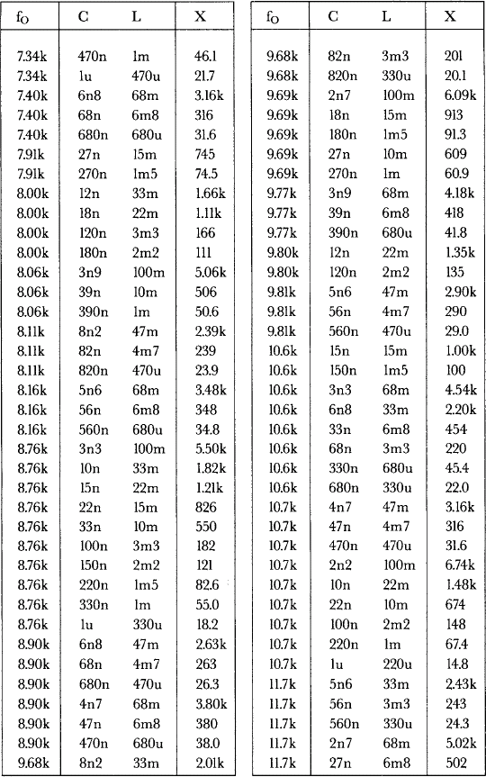
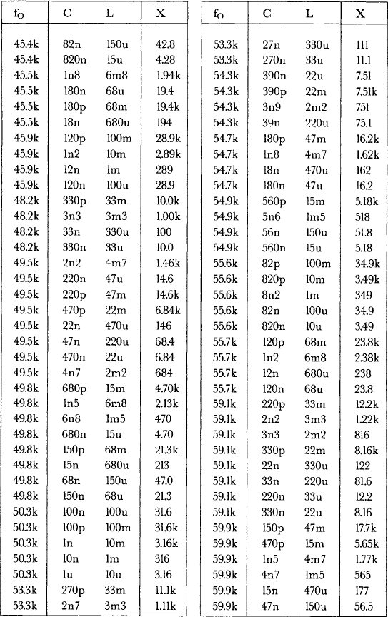
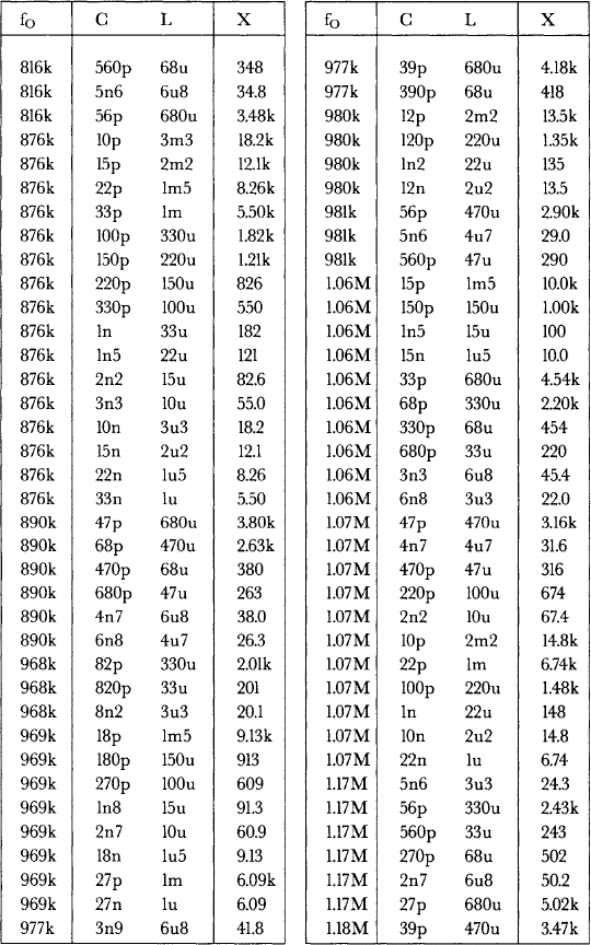
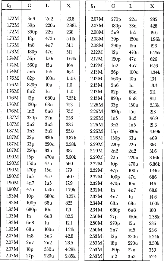
Table 10.1 lists the resonant frequencies from 500 Hz to 50 MHz obtainable with E6 inductors and E12 capacitors. A column is also provided, X, showing the value of XC or XL at resonance. This can be used to find the highest possible Q, provided that the resistance of the inductor is known.
Parallel tuned circuits
A parallel tuned circuit consists of a capacitor and an inductor in parallel. The circuit can be understood by using a similar approach to the one which we took for the series tuned circuit. However, the practical circuit is slightly complicated by the fact that the inductive branch possesses more resistance than the capacitive branch, which makes it somewhat asymmetrical. In many cases this effect can be ignored, but not all, so we need to be able to predict whether it will be significant or not. But to make the analysis one step at a time, it makes sense to start by considering an ideal version of the circuit, where the effect does not come into play at all.
The ideal parallel tuned circuit
This consists of an ideal inductor and capacitor in parallel – each has no resistance. In this circuit we take the voltage across the circuit, VIN, as our phase reference, as it is common to both components, and look at the current that each branch draws from the source at different frequencies. These currents will always be in antiphase – the capacitor’s current, IC, leading VIN by 90°, the inductor’s, IL, lagging. The input current, IIN, will be their phasor sum. As they are in antiphase, their phasor sum is simply the difference between them.
We can once again say that XC will fall with increasing frequency, and XL will rise. And once again, XC will equal XL at some frequency, that given by Eqn (10.1). At this frequency, again fO, the current in each branch will be equal, and hence the input current will be zero. The impedance is ![]() , and is infinite. The circuit looks like an open circuit to the source at resonance, and its resonant frequency is calculated identically to that of the series tuned circuit.
, and is infinite. The circuit looks like an open circuit to the source at resonance, and its resonant frequency is calculated identically to that of the series tuned circuit.
Below resonance, the capacitor will have the greater impedance of the two devices, and the impedance will appear inductive with current lagging voltage by 90°. Above, the inductor possesses more impedance and the impedance is capacitive, with VIN in lagging IIN.
At resonance, the input current is zero, while IC and IL are ![]() and
and ![]() respectively. The Q factor,
respectively. The Q factor, ![]() or
or ![]() in would therefore be infinite.
in would therefore be infinite.
The practical parallel tuned circuit
The practical circuit differs from the ideal mostly in that the inductor possesses resistance. Such a circuit is shown in Figure 10.2, with RL representing the internal resistance of the inductor.
The addition of the resistive element in series with the inductor causes IL to be less than 90° lagging VIN. In turn, this causes at the frequency at which XC =XL to be leading VIN by some angle, rather than in phase, as it was with the ideal circuit—the circuit is overall capacitive, rather than resistive. To compensate, and bring VIN back in phase with VIN, making the circuit truly resonant, the frequency of VIN must be lowered. This has the effect of making IC smaller and IL larger. It can be seen that the effect becomes more pronounced the greater the inductor’s resistance is, compared to its reactance.
To what degree all this affects Eqn (10.1) depends on the Q of the inductor at the resonant frequency, as defined in Eqn (10.4).
Resonant frequency error
The resonant frequency as found from Eqn (10.1) must be multiplied by the term:
to find the true resonant frequency. In practice, the Q has to be pretty low to cause much deviation; a Q of 4 gives k = 0.97, a Q of 2 gives k = 0.87. Eqn (10.1) is often used as it stands.
Dynamic impedance
The practical circuit no longer looks like an open circuit to the source at resonance. Its impedance is purely resistive however, and is often called the dynamic impedance. It is given by:
From this we can see that dynamic impedance is inversely proportional to the resistance of the inductor.
Q factor
With the practical parallel tuned circuit the Q is, as with the series resonant circuit, the same as the Q of the inductor at the resonant frequency. We might ask ourselves what happens when we wish to deliberately reduce the circuit’s Q; for if we placed our damping resistor in series with the inductor, it would also affect our resonant frequency. The solution is that the damping resistor is placed across the whole tuned circuit, as shown in Figure 10.3, where it has the desired effect without affecting fO. The value of the damping resistor can be calculated as follows:
where RD is the damping resistor value, QD is the desired Q(Q damped), ![]() as previously, and QI is the Q of the inductor at resonance, or the Q of the circuit with no damping resistor. QD must obviously be less than QI.
as previously, and QI is the Q of the inductor at resonance, or the Q of the circuit with no damping resistor. QD must obviously be less than QI.
Maximum capacitor value
We can see that as R becomes larger, k Eqn (10.6) goes from 1 towards zero, and the resonant frequency falls, also towards zero. When:
then k = 0, and the circuit ceases to resonate. This tells us that for any practical inductor, there is a maximum value of capacitor which can be placed across it for it to remain resonant. This value is easily calculated from Eqn (10.9).


