Chapter 1
Electron Dynamics and Cathode Ray Oscilloscope
1.1 Motion of Charged Particles in Electric Fields
The subject of electronics deals with playing with electrons. Since any play involves movement, it is necessary to study the dynamics of electrons. The push-pull action of potentials (positive and negative) on electrons can be used to realise many electronic gadgets including basic electronic devices. However, the dynamics of electrons as stimulated by external fields opens its discussion under the following assumptions:
- Electrons responsible for the conductivity do not experience mutual coulombian forces owing to the fact that charge density is very small.
- An electron carries a mass 31 orders less than what we measure with macroscopic mass, the gravitational forces that operate among the conducting electrons are negligible.
- Under the guise of free electron theory for conductivity, the particles are supposed to drift without collisions either with themselves or with the walls of the container.
The following are the characteristics of electrons treated conceptually as a particle:
It is noted that a kilogram of electrons contain 1.1 × 1030 electrons and a coulomb of charge (−ve charge) rests with 6.25 × 10¹⁸ electrons approximately.
Inasmuch as all electrons according to classical model are charged particles, magnetic and electric fields could induce motion in them. Once the solid nature of the electron is accepted we can apply all laws of dynamics to electrons and study their movements (trajectories) in electric and magnetic fields. However, this simple model remains valid in vacuum tubes like Cathode Ray Tubes (CRTs), and so this discussion will be limited to such devices.
For other devices the more rigid wave mechanical model yields accurate results.
1.2 Force on a Charged Particle in an Electric Field
By definition the force on a unit positive charge at any point in an electric field is the field intensity ε at that point. For example, the force on a unit positive charge in a field of 1 V/m is one Newton.
The force fq on a positive charge of q coulombs in a field of intensity ε V/m is given by the expression
To determine the locus of the particle we use the equation (1.2).
According to Newton’s second law of motion,
in the above expression m is the mass, a is the acceleration, v the velocity and t the time in corresponding units. (In MKS system m is in kg, a in m/s2, v in m/s and time t in seconds.)
When the charge is an electron, the force fe acts in the opposite direction and results in
1.3 Motion of an Electron in a Constant Electric Field (Initial Velocity along the Axis of the Field)
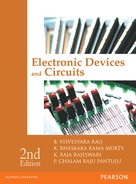
The simplest case is when the electron is situated between the plates of a parallel plate capacitor as shown in Fig. 1.1. We assume that the field is uniform based on the fact that d the distance between the plates is small compared to the dimensions of the plates as is the fact in all practical cases.
The parameters are defined as follows:
Vx = velocity of electrons in the X direction
x = distance in the X direction
t = time.
At t = 0, the initial velocity v0x and the initial position x0 of electrons are termed the initial conditions.
In Fig. 1.1, no forces are shown in the Y and Z directions and so there is no acceleration in the Y or Z directions. But it should be remembered that zero acceleration means constant velocity. Since in the one-dimensional model f y and f z are zero, ay and az are zero, the electron moves in the X-direction only.
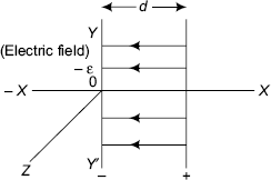
FIGURE 1.1 Parallel plates
Applying Newton’s second law to the above model,

(vx − vox) = axt
vx = vox + axt (similar to v = u + at) (1.6)
Again,
dx = vxdt
dx = (vox + axt)dt

Potential
From equation (1.5),
![]()
∵ dx = vxdt (1.9)
Multiplying the L.H.S. of (1.8) by L.H.S. of (1.9) and doing the same with R.H.S., the following result is obtained:
Integrating (1.10) subject to the initial conditions
The expression ![]() is nothing but the work done on the electron in moving it against the field from x0 to x and is by definition
is nothing but the work done on the electron in moving it against the field from x0 to x and is by definition
Substituting (1.12) in (1.11), we obtain
qV is the (potential) energy associated with the electron due to its presence in a field of potential difference (V) volts.
[The energy in general is expressed in joules, that is, 107 ergs or 107 Dyne-cm. This is too big a unit in the context of Electron Dynamics and a smaller more practical unit is conceived. This smaller unit of energy is called the electron volt expressed as eV. If an electron falls through a potential difference of 1V, its potential energy (P.E.) decreases by an electron volt. Thus, one electron volt eV = e × 1V joule = 1.6 × 10⁻¹⁹ joules or an eV = 1.6 × 10⁻¹⁹ joules.]
The R.H.S. of the equation (1.13) is clearly the kinetic energy associated with the electron and the L.H.S. represents the potential energy (P.E.) (energy due to position). In other words, it is a statement reiterating the ‘law of conservation of energy’. As the electron leaves the −ve plate, it has only potential energy. It acquires kinetic energy (K.E.) as it moves towards the + ve plate. Thus, it has some P.E. and some K.E. At the + ve plate, it becomes fully K.E. But always subject to the condition that W = P.E. + K.E; where W is the total energy.
[An analogy can be drawn here to a stone on a wall at height h metres and freely falling due to a push. During the transit, it has some potential energy (P.E.) and some kinetic energy (K.E). The net energy is always the same. At any point x the P.E. is mgx and the K.E. = ½ mv2x].
By definition the potential energy at a point in an electric field is equal to the product of charge q and the potential at that point. That is,
From the equation (1.13); if Vox = 0 at t = 0, we get
or,
Lower case v is used for velocity and upper case V for potential or voltage.
Initial Velocity Perpendicular to Electric Field
If an electron enters a decelerating field as shown in Fig. 1.2 between two parallel plates with an initial velocity vox, the velocity decreases with time (as does the velocity of a stone thrown up against gravity). If conditions permit the electron may reach the other plate (curve 1) or reverse its direction even earlier (curve 2).

FIGURE 1.2 Electron trajectory
In this case, the rules vx = [v0x − axt] and x = [v0xt − ½ axt2] apply. In case it cannot reach the upper plate it returns back with a velocity of | axt | after travelling a distance d = ![]() ax t2.
ax t2.
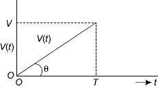
FIGURE 1.3 Voltage V(t) as a function of time
It is neither necessary for the field to be uniform nor time invariant. The only difference it makes is that the proper expression has to be used. For instance, if the voltage varies with time t, V (t) instead of V has to be used together with the relevant expression for V (t) and the incremental expressions (d/dt…) have to be used.
Here,
If V(t) is a linearly varying function as shown in Fig. 1.3,
If it is sinusoidal and the angle θ is small (sin θ, where θ is small) the power series is utilised to evaluate the expression.
that is, sin θ = θ – θ3/3! + θ5/5! – + …
We approximate it to sin θ = 2π ft; therefore, Vm sin θ = Vm (2π ft).
The other rules remain the same. Since v is a function of time we have to use differentials instead of the simple formulae
aydt = dvy
vydt = dy

If the charge carrier enters the field at an angle with an initial velocity then it is resolved into the X and Y components by the usage of vx = vθ cos θ and vy = vθ sin θ, where θ is the angle at which it enters the field.

FIGURE 1.4 Charge carrier enters the field at an angle
1.4 Two-dimensional Motion of Electrons
The motion of an electron is investigated, with an initial velocity in the X direction and a field in the Y direction and with the field being uniform. No other fields exist in this region.

FIGURE 1.5 Two-dimensional electronic motion
The initial conditions are
After it enters the field at t = 0
The velocity vox remains constant, since ax = εx = 0 at t = 0.
So, the distance in the X direction it travels is ![]()
But there is a constant acceleration in the Y direction so that vy = ayt; and ![]()
The trajectory of the electron can be known by finding the equation of motion.
From ![]()
y can be found in terms of Vox from the equation, x = Voxt
This equation is in the form of ![]() = x2 tan θ.
= x2 tan θ.
So, the electron path is parabolic.
1.5 Electrostatic Deflection in a Cathode Ray Tube (CRT)
Electrons from an electron gun are accelerated by a potential Vax in the X direction and enter the transverse field of Vd with an initial velocity of ![]()
Due to Vd, the electrons get deflected, reach the end of the plates at p and since there is no accelerating field beyond point p, they continue in a linear path and touch the screen at point p′as shown in Fig. 1.6.

FIGURE 1.6 Electrostatic deflection in a Cathode Ray Tube
The equation of motion up to point p between the plates is as given by the equation ![]() So, the electrons will move in a parabolic path up to point p.
So, the electrons will move in a parabolic path up to point p.
From there, the equations of the straight line pp′ decides the motion of the electron and can be found from the equation of the straight line as per the geometry of the Fig. 1.6. The straight-line path from the edge of the deflecting plates to the screen is a tangent to the parabolic path between the plates at that point.
But,
Therefore,

On simplification,
When, x = l/2; y = 0 or the straight line pp′ when projected backwards intersects the X-axis at o′. At x = l/2; that is o′ bisects the line.
The deflection D can be found from the geometry again.
So,
But,
Substituting these values,
Thus D ∝ Vd.
∴ the deflection sensitivity;
From the equation (1.24) for deflection sensitivity, the deflection sensitivity S is independent of the charge and mass of the electrons. Reducing d and Va increases the sensitivity. L and l have limitations in view of the construction of the equipment.
1.6 Motion of Charged Particles in Magnetic Field
Magnetic Deflection
Since a moving electron constitutes current and a current carrying conductor produces a magnetic field, electrons are affected by magnetic fields. This property can be utilised to deflect electrons in the cathode ray oscilloscope and this method proves better compared to electrostatic deflection in some specific applications like TV (television) picture tubes.
It has been verified experimentally that if a current carrying conductor of length L in metres is in a magnetic field of strength B, the conductor experiences a force fm and is given by
where fm is in Newtons, I in Amperes and B in Webers/m2 or Tesla.
This is subject to the condition that the directions of B and I should be perpendicular to each other. Then, the force fm can be represented by the motion of a right-handed screw placed at the origin O and advanced into the plane containing I and B and moves through 90° from I to B as shown in the following Fig. 1.7.
FIGURE 1.7 Direction of force fm on a charged particle situated in a magnetic field
B and I need not necessarily be perpendicular to each other. In this case the component of I resolved in a perpendicular direction to the direction of the magnetic field will be responsible for the force on the conductor. A word of caution is necessary in this context.
The figure represents the situation when the current is due to conventional positive charges. On the other hand, if the current is due to the electrons, the direction of motion is anti-parallel as shown by v−. This can be applied to moving electrons in any medium in the following manner. A conductor of length L contains N electrons.
If N electrons pass through a length of conductor L metres of cross-section A m2 in time T seconds, as shown in Fig. 1.8, then the current I can be computed as

FIGURE 1.8 Conductor of length ‘L’
Where T is in seconds, q is charge of an electron, and Nq is the total charge carried by electrons in the conductor in coulombs.
If the electrons move with a velocity v m/s, then T will be L/v seconds.
Now, the force BIL will become
Therefore, the force fm per electron will be Bev
This equation (1.27) is special case of the general equation
Motion of an Electron in a Magnetic Field
The above expression (1.27) shows that electrons experience motion when subjected to magnetic fields. This can be extended to a beam of electrons moving with a velocity v entering a magnetic field. If there is a velocity component v perpendicular to the direction of the field B, it experiences a force in a direction perpendicular to both the field and direction of motion of electrons. Hence, the condition required for the electron to move is that its motion is always directed perpendicular to the magnetic field B as well as to the direction of velocity v (current).

FIGURE 1.9 Circular motion of an electron in a transverse magnetic field
It implies that the force accelerates the electrons but does not affect the magnitude of the velocity, so it changes only its direction. (If a force acts on an electron, it should be accelerated according to the equation f = ma. This by no means, means that the magnitude of velocity has to change. But, instead, the force may cause a change in direction).
Further, as the direction of the force is perpendicular to the direction of motion, no work can be done on the electron. (Work done W = f.S. cos(θ) = 0; if cos(θ)= 0, that is, θ = 90°. Since f and θ are not zero, only the distance S travelled in the direction of force is zero.)
Since it is necessary that the direction of the force and the direction of the motion are always to be perpendicular, the resulting motion should be a circle, the radius of which depends upon the field and the velocity as derived below.
Thus, the force on the electrons Bev is equal to the force due to circular motion. From classical dynamics, the force on a particle in circular motion is mv2/R and these two should be equal.
i.e
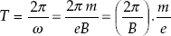
Therefore, the time period for one revolution T is as follows:
where ω is angular frequency.
Since
(from classical mechanics) ![]()
From the equation (1.29), the time period for one revolution T for one electron
It is found that the time period T is independent of the velocity and so, electrons travelling with different velocities can have the same time period of revolution. The radius R is dependent on both velocity and field, being directly proportional to the velocity and inversely proportional to field. Thus, electrons entering with a specific velocity travel circular paths of decreasing radius as the field increases.
The time period for one revolution T and ω are independent of speed and/or radius. As radius R is proportional to velocity (R ∝ v), faster moving particles will traverse larger circles in the same time while a slower particle describes a smaller circle. This concept is used in focusing in instrumentation.
1.7 Motion of an Electron in Helical Paths
Magnetic Focusing
It is seen that if an electron enters the magnetic field perpendicular to the direction of field, the locus is a circle. If it is parallel, no force acts and it continues to be at rest (if initial velocity of electron is zero) or maintains the same-velocity Vo. If on the other hand, an electron enters the field at an angle θ as shown in Fig. 1.10, it will have a component each in directions parallel and perpendicular to the field. The parallel component of the velocity Vθ sin θ will not change, since it experiences no force in that direction. But the X-component, Vθ cos θ experiences a force to cause it to move in a circle in the X−Z planes. The resultant motion is helical path as shown in the Fig. 1.11.

FIGURE 1.10 Electron entering the field at an angle θ
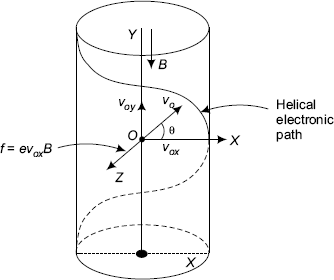
FIGURE 1.11 Helical path of an electron entering at an angle to the field B
The electron describes a helical path, wherein the electron with an axial symmetry (cylinder) moves along the pitch of the helix. Pitch of the helix in defined as the displacement along the parallel component of the field while the perpendicular component undergoes one revolution.
The pitch of the helix p is (voy × T) where T is the time period.
Pitch of the helix
Electrons entering the field at different angles (perhaps due to mutual repulsion among them) will travel circular paths of varying radius, but may have the same pitch. This principle can be used to bring electrons of a diverging beam into focus at a point. As the field increases, as it is seen electrons travel in smaller and smaller circular paths with the same pitch and can be made to focus at a point on a screen, with the distance between the origin and the screen corresponding to integral number of pitches. This method of focusing the electrons to any point is called magnetic focusing.
The previous discussion shows that electrons can be deflected and focused. This ability of deflection can be used for deflections in cathode ray tubes, especially in TV tubes and computer monitors. This has additional advantages compared to electrostatic deflection.
For a given anode voltage, the deflection sensitivity is more for magnetic deflection. Correcting factors can be introduced externally in the form of superimposed wave forms.
One disadvantage is that the deflection for heavier unwanted negative ions is less and they cause sputtering (central dark spot on the screen due to heavy ion bombardment) of the screen. This can easily be avoided by using an ion trap in the form of aluminum coating on the inside of the screen.
1.8 Magnetic Deflection in a Cathode Ray Tube
In a cathode ray tube electrons produced by the cathode K are accelerated to the fluorescent screen using electric fields known as ‘electron lens system’ containing accelerating and focusing electrodes. Signal wave forms are displayed by applying them to a set of X and Y plates (electrostatic diflection) or a set of coils to produce magnetic fields (magnetic deflection).
Fig. 1.12 explains the magnetic deflection in a cathode ray tube. A coil is wound on the constricted portion of the tube over a small length l. Over this length, the field is considered to be uniform and the length of the field l is small compared to L, which is the distance between the centre of the magnetic field O′ and the screen of the cathode ray tube.
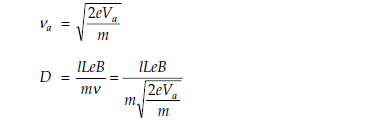
Electrons accelerated by an anode voltage Va enter the field with a velocity ![]() (Therefore v = 5.93 × 10⁵ √Va m/sec).
(Therefore v = 5.93 × 10⁵ √Va m/sec).
The path of the electron beam is circular between the ends of the field, that is, O to M and a straight line, at an angle φ from the end of the field, that is M to P′ to the screen with reference to the Fig. 1.12.
Since l is much less than L;
where D is the deflection of the beam from the centre of the screen, tan φ ≅ φ; since φ is very small.
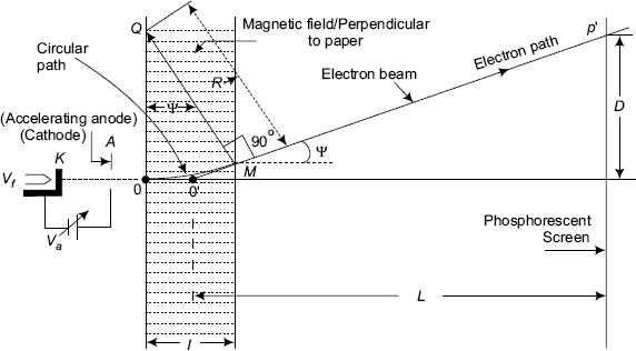
FIGURE 1.12 Magnetic deflection in a Cathode Ray Tube

Subtituting for

That is, D ∝ B.
Magnetic Deflection Sensitivity
Magnetic deflection sensitivity ![]() (By definition)
(By definition)
Equation (1.32) for magnetic deflection sensitivity Sm of the cathode ray tube suggests that the quantity B, the magnetic field intensity, does not have any influence on Sm.
The deflection sensitivity Sm increases with L where L is the distance from the centre of the magnetic field and the screen of the CRT as shown in the Fig. 1.12. This suggests the location of the coils producing the magnetic field on the cathode ray tube depending upon the practical applications.
Further, magnetic deflection sensitivity is inversely proportional to ![]() and so, it is better than ‘electrostatic deflection’; for which it is inversely proportional to Va. Higher anode voltages are needed to produce more intense spots on the screen in both electric and magnetic deflection systems.
and so, it is better than ‘electrostatic deflection’; for which it is inversely proportional to Va. Higher anode voltages are needed to produce more intense spots on the screen in both electric and magnetic deflection systems.
But unfortunately, from above discussions, it is found that the deflection sensitivity decreases for higher anode voltages and thus they are conflicting requirements. This can be partially compensated by post-deflection acceleration of the beam.
If the field extends over the entire length of the beam, the calculation of deflection should be done as follows:
From the Fig. 1.13, it can be seen that the path of the electron OP′ is the arc of a circle of radius R given by ![]() metres.
metres.
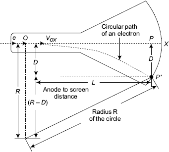
FIGURE 1.13 Circular path of an electron beam in a Cathode Ray Tube
Velocity v can be known from the knowledge of the accelerating anode voltage Va.
In this deflection (P − P′), that is, D can be known from the geometry of the figure by applying Pythagoras theorem, as following:

An example for this is found in nature in the effect of earth’s magnetic field on the deflection sensitivities of CRTs. So, shielding has to be provided to protect the CRT from the magnetic effects of earth.
The presence of the earth’s magnetic field adversely affects the performance of CRT’s, since the actual deflection is due to both deflection field and earth’s magnetic field. By changing the orientation of the tube, so as to make the earth’s field parallel to the axis of the tube, the additional deflection can be nullified.
1.9 Electrostatic Focusing
It is known that if a light beam comes to the interface of two media of refractive indices μ1 and μ2, it refracts. This principle is used to focus the optical beams through lenses. This analogy can be utilised to conceive a method of focusing electron beams through electrostatic lenses formed by curving equipotential surfaces.
Consider an electron approaching an equipotential surface with voltages V0 and V1 on either side, with a velocity v0 as shown in the Fig. 1.14.
The energy of the electron is given by
the velocity ![]()
Referring to the Fig. 1.14. the voltages on either side of the equipotential surface are V0 and V1 with V1 > V0. Since the velocities v are proportional to ![]() (the voltages) v1 > v0. The electron enters on V0 side with a velocity v0 and crosses to the other side and proceeds with a velocity of v1.
(the voltages) v1 > v0. The electron enters on V0 side with a velocity v0 and crosses to the other side and proceeds with a velocity of v1.
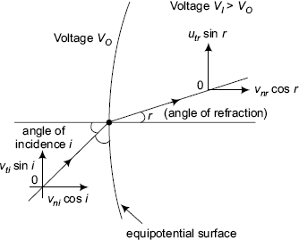
FIGURE 1.14 Concept of electron lens effect in a CRT
Practical focusing system (electrostatic focusing) Since, the particle enters at an angle ![]() i, it has vti and vni; the tangential and normal components as shown in the Fig. 1.14. It leaves at an angle r and velocity vr with components vnr and vtr; since the tangential component on which no work is done should not change.
i, it has vti and vni; the tangential and normal components as shown in the Fig. 1.14. It leaves at an angle r and velocity vr with components vnr and vtr; since the tangential component on which no work is done should not change.
∴ vti. sin(i) = vtr. sin(r) however, vni. cos(i) ≠ vnr. cos(r)
Thus, vti. sin(i) = v0. sin(i) and vtr. sin(r) = v1. cos(r)
∴ v0. sin(i) = v1. sin(r)
∴ ![]() (1.35)
(1.35)
In designing lenses the equipotentials have to be chosen to suit one’s requirements since they decide the electron paths. The one shown in Fig. 1.15 is called a double aperture lens. In CROs the following one is more often used.

FIGURE 1.15 Practical focusing system (double aperture lens)

FIGURE 1.16 Symmetrical electron lens
Fig. 1.17 shows an asymmetric lens system The geometry is self-explanatory.

FIGURE 1.17 Assymetrical lens system
1.10 Cathode Ray Tube
Cathode ray tube is the main unit in a cathode ray oscilloscope (CRO). A cathode ray tube, power supply (for providing accelerating and focusing voltages and voltages to other electronic circuits) circuits, sweep circuit to generate sweep wave form, horizontal amplifier, vertical amplifier for deflecting voltages and some control circuits form the various blocks of a CRO.
For complete understanding of the various circuits in CRO, the knowledge of various details of working of a Cathode Ray Tube are necessary.

FIGURE 1.18 Structural details of a Cathode Ray Tube
Cathode supplies electrons for movement through vacuum inside cathode ray tube. Electrons are produced from the indirectly heated cathode (source for electrons) because of thermionic emission, governed by the expression:
I = current due to emitted electrons from cathode by thermionic emission.
S = surface area of cathode (Cathode Assembly)
Cathode is made of thorium oxide coated tungsten material. A and b are the constants of the tungsten material. ɸ is the work function, the energy required for the liberation or emission of electrons from the cathode surface, and T = absolute temperature in degrees Kelvin.
The electrons emitted from the cathode surface are deflected electronically to reach the screen on the cathode ray tube. The point of impact of the moving beam of electrons on the screen is visible, because of the phosphorescence property of the (P - 11 phosphorus) coating material on the screen. The screen contains natural and synthetic materials to give the desired colour (yellow or green) response and fluorescent properties. Different phosphorescent materials are available which provide image persistence for short or long times; so very high frequency or low frequency signals can be observed on the screen comfortably. The electrons are returned back through acquadug coating on the inner surface of the CRT. Voltage wave forms can be observed on the screen of the CRT in association with some more electronic circuits in the cathode ray oscilloscope (CRO).
Since the mass of the electron is quite small, so is its inertia. Thus, very high frequency voltages even can deflect a beam of electrons emitted from the cathode surface. Owing to the charge of the electrons, varying electric or magnetic fields in the region between the cathode and screen can deflect the beam.
Control grid ‘G’ has a small hole in its centre and allows or transmits a pencil beam of electrons. The beam current and spot intensity on the CRO screen can be varied by the adjustment of control grid bias Vcg, where control grid voltage Vcg is maintained at negative bias. Intensity or brightness control on the front panel of CRO corresponds to this function.
This beam of electrons emerging from the hole of the control grid are accelerated and focused into a small point on the screen by anode assembly that functions as an electron lens or electric field lens system. The voltage on the first anode in the anode assembly provides the focusing control on the front panel of CRO. The complete beam forming assembly is known as the electron gun.
The electron beam from the electron gun passes between two pairs or sets of parallel plates and reach onto the screen of the cathode ray tube, producing a spot of light, the colour of which depends on the type of phosphor coating on the screen:
The two sets of plates are known as
- Horizontal deflection plates, or X-plates or X-deflection plates.
- Vertical deflection plates or Y-plates or Y-deflection plates.
The sweep voltage internally applied to the X-plates controls the movement of electrons in the horizontal or X-direction. As the control or movement of electrons is in the X-direction, the name for the plates is X-plates. The sweep voltage is also known as time base voltage. The shape of sweep voltage is like a sawtooth wave.
The signal voltages to be observed are applied to Y-plates and the applied voltages control the movement of electrons in the vertical direction. As the control or movement of electrons is in the Y-direction, the name for the plates is Y-plates. These two sets of deflecting plates are mutually perpendicular as shown in the Fig. 1.19.
For instance, if no D.C. voltage is applied to X-Plates and the spot is at point A, application of a D.C. voltage to the X-set of plates with right hand side plate positive with respect to the other, the spot shifts to point B. This shift in the X–direction is proportional to the applied voltage, as shown in the Fig. 1.19A and the spot stays there as long as the voltage is present and returns to point A, on removal of the D.C. voltage.

FIGURE 1.19 Mutually perpendicular deflecting plates (X-Plates and Y-Plates)

FIGURE 1.19A Spot movement from point ‘A’ to point ‘B’ due to applied D.C. voltage to X-Plates of a CRT
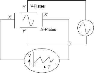
FIGURE 1.19B Vertical deflection due to voltage applied to Y-Plates
The same reasoning applies to Y-plates; with the only difference that the electron beam moves (under the influence of fields) in the vertical or Y-direction instead; that is electric field between Y-plates deflects the beam of electrons in a direction normal to the plane of the plates.
For example, if we want to see the wave form of a sinusoidal voltage applied to Y-plates, we have to provide the time axis (time base) voltage or sweep voltage internally to horizontal deflection plates. Since, a sinusoid is a graph with the Y-coordinate as amplitude of the signal and X-coordinate corresponding to the instance of time at which the instantaneous value of voltage Vac, that is, Vac = Vm sin (ωt).

FIGURE 1.20 Trace of a sinusoid
This means that a pull in the X-direction is proportional to time according to the following equation:
or, a ramp type voltage that has to be applied to the X-plates.
If T corresponds to the time period of the signal just one passing trace appears.
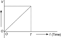
FIGURE 1.21 Time base (ramp) voltage
To get a solid trace, the cycle has to be repeated at a rate more than the persistence of vision of the human eye, that is, at least of the order of 25 traces per second. An additional requirement is that the starting point of every new trace should coincide with the beginning of the previous one. This is called synchronisation. The repetitive trace can be obtained by using a repetitive triangular wave (also known as sawtooth voltage) generator called sweep generator (the sweep voltage applied to X-plates controls the sweeping of electrons, that is, movement of electrons in the X-direction).
Time base generator (the time functional behaviour of the signal to be observed is provided by the time base voltage) provides the sweep voltage for sweeping electrons in the X-direction inside the cathode ray tube. One of the simple methods of generation of such voltage using a UJT oscillator circuit is described in the next section.
UJT Relaxation Oscillator
A very simple method of getting a repetitive triangular wave is shown in the Fig. 1.22. The circuit is a UJT relaxation oscillator.
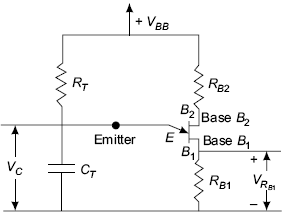
FIGURE 1.22 UJT (Unijunction transistor) relaxation oscillator
The action of the UJT relaxation oscillator circuit is explained in the following manner. The UJT acts as a switch. It conducts (ON-state) when the emitter to base one voltage, VEB1 is more than VP and it goes to OFF-state when VEB1 ≤ Vmin that is Vγ. In the RT, CT circuit to which VBB is applied, the voltage across the capacitor rises with time exponentially (but linear over a very small period). By the time, the voltage across the capacitor reaches a particular value VP (peak voltage for the UJT to conduct) the UJT suddenly starts conducting and the capacitor will be discharging through the input circuit path of the UJT in the conduction state. When the capacitor voltage falls below a certain value Vmin (Vγ), the UJT goes to the OFF state and becomes nonconducting. Then, the capacitor starts charging all over again only to be discharged when Vcapacitor = Vpeak.
This process repeats and a wave form of voltage Vc can be obtained across the capacitor CT in the UJT relaxation oscillator circuit. The wave form is shown in Fig. 1.23 (refer to Chapter 6 for more details).
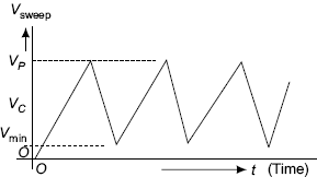
FIGURE 1.23 Sweep voltage across capacitor CT of relaxation oscillator
1.11 Cathode-Ray Oscilloscope (CRO)
Control Switches on the Front Panel of CRO
1. Focusing control This controls the voltage on the focusing (electron lens system) anode to produce a finely collimated spot on the Cathode Ray Tube (CRT) screen in the absence of any signal voltages on the X and Y plates.

FIGURE 1.24 Block diagram of a CRO
2.Shift or position controls There are two position controls, namely, horizontal position control and vertical position control. Thus, there are separate position controls for vertical and horizontal positions. The voltages applied to the control assembly in the CRT will be used to bring the spot to any required position (X or Y) on the screen.
3. Voltage gain controls (for X and Y amplifiers) These are stepped rotary controls with voltage level calibrations indicating the actual value of the voltages by multiplying the signal trace lengths and the volts/cm calibrations as indicated on the panel at the respective control knobs. These are the amplifier gain controls for the X and Y amplifiers.
4. Time base or sweep voltage and frequency controls There are two types of time base controls. One type of sweep control is used to connect the internal sweep voltage to the X-plates of CRT at the INT position of the control switch. At the EXT position of the control switch, the time base generator can be switched off and any external signal to the X-plates can as well be given for special applications, such as for a signal frequency measurement using Lissajous figure patterns. This is indicated on a switch which when kept in INT position includes the sweep generator inside the CRO Unit and in the other EXT position, excludes the same.
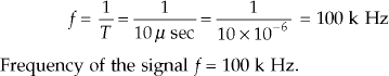
There is a second type of control for controlling the frequency of the sweep voltage. If the time base period set on the control knob corresponds to the time period of the signal to be observed, just one sinusoid or one cycle of signal will appear on the screen. On the other hand, if the time base period is ‘n’ times the time period of the signal under investigation, ‘n’ cycles of traces of the signal appear on the screen. These are marked on the panel at the respective control knob as time in seconds (s), milliseconds (ms), or microseconds (μ s) per cm of length on the screen. For example, if there is one wave form of a signal of time period T of one cm and the marking at the control knob on the front panel is 1 ms/cm, then the frequency f of the signal is 1000 Hz.
It is calculated by using the following relation between frequency and time. Frequency,
5. Horizontal and vertical amplifiers These amplifiers are used to increase or enhance the input signal applied to the horizontal and vertical plates, respectively and allow a reasonable magnitude for the signal traces on the screen for easy or convenient observation and measurement.
6. Channel controls Mostly, the cathode ray oscilloscopes are dual trace oscilloscopes. There will be two channels, namely, channel one and channel two, so two signals can be observed simultaneously at a time. There are separate controls to use channel 1, channel 2 or the two channels at a time for signal observations.
1.12 Applications of CRO
Measurement of Voltage
Voltage of a signal is measured by observing the wave form on the screen of a cathode ray oscilloscope by measuring the height of the peak of the signal. The magnitude of the voltage is obtained by multiplying the observed value by the scale factor marked as Volts/div on the control panel of CRO around the voltage setting control knob.
If the signal is applied to the Y-plates and the sweep generator is switched off by keeping the sweep control in external position (Ext), a vertical line whose length corresponds to peak-to-peak value of the signal voltage applied to Y–plates is observed (thus, it becomes a peak reading voltmeter as well) as shown Fig. 1.25, 1.26 and 1.27.
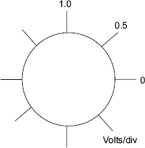
FIGURE 1.25 Voltage setting control
If the signal is large enough and can be directly applied to the deflection plates, it represents an ideal voltmeter with infinite self-impedance.
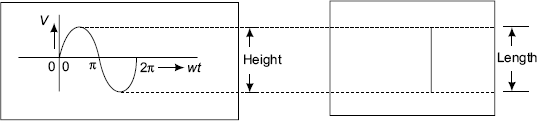
FIGURE 1.26 |
FIGURE 1.27 |
Current Measurement
By opening the circuit and introducing a small resistor, small enough not to disturb the current in the circuit, current can be measured. Apply this voltage developed across the resistance to the CRO Y-plates. Calibration of the measured voltage is done in terms of current by drawing a graph between known voltages and currents. The magnitude of the current can thus be measured.
Frequency Measurement by Comparison using Lissajous Figures
One method of frequency measurement is already indicated under sweep generator topic by measuring the time period of a cycle of the signal, whose frequency is to be measured.
A second method is to compare the frequency of a known signal from a signal generator applied to X-plates and the signal under measurement to Y-plates of a CRO. When the amplitudes and frequencies are same, a circle appears on the screen. Thus, the unknown frequency can be known by reading the frequency of the known source. (Refer Fig. 1.28)
During this measurement, internal sweep is to be switched off.
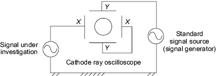
FIGURE 1.28 Frequency measurement
If on the other hand, the frequency ratio of the signals applied to X and Y plates is ![]() (fx is frequency of the known source), two loops appear along Y-axis. When
(fx is frequency of the known source), two loops appear along Y-axis. When ![]() then n-loops will appear in the X-direction.
then n-loops will appear in the X-direction.
If a signal from a known source is phase split by an R-C network and the voltages across R and C elements are applied to X and Y plates of the CRO, a circle appears on the screen. If now, the signal whose frequency is to be measured is applied to the intensity control (z-terminal on the CRO) and if the signal amplitude is sufficiently large enough, the circle on the screen is split into a number of segments. The number of segments on the circle gives the number ‘n’ by which the known signal frequency is to be multiplied to obtain the frequency of the unknown signal. (Refer Fig. 1.29 and 1.30)

FIGURE 1.29 Frequency ‘fn’ determination of unknown signal using spot wheel pattern

FIGURE 1.30 Frequency measurement of a signal using spot wheel pattern
Comparison between Electrostatic Deflection and Magnetic Deflection
Electrostatic Deflection Electrostatic Deflection, ![]()
where |
D = deflection in metres |
|
L = distance from centre of deflection plates to screen in metres |
|
l = length of deflection plates in metres |
|
Vd = deflection voltage in volts |
|
d = distance between plates in metres |
|
Va. = acceleration voltage |
Deflection Sensitivity Deflection sensitivity is defined as vertical deflection of the beam per unit deflection voltage.
Deflection factor G of a CRO is the reciprocal of deflection sensitivity S
Electrostatic Deflection
- Speed of deflection is faster.
- For greater sensitivity, long plates with minimum distance between them is necessary. So, the CRT will be long and beam potential will be less.
- Deflection plates limit the beam angle. To correct this, plates are bent or curved instead of being parallel.
- Segmented plates are used for large bandwidth. Maximum bandwidth is up to 350 MHz operation.
- Amplifiers with low current requirements are sufficient.
- Cathode Ray Oscilloscopes using CRTs are used in laboratories for display, measurement and analysis of signals.
- Deflection sensitivity is independent of deflecting voltages Vd.
- Deflection sensitivity is inversely proportional to accelerating voltage Va for electrostatic deflection, and for magnetic deflection sensitivity is inversely proportional to ÖVa. So, for electrostatic deflection larger voltages are needed to obtain the same sensitivity.
- Electrostatic deflection suffers defocusing.
Magnetic Deflection
Magnetic Deflection, ![]() metres
metres
where, |
l = width of magnetic coil in metres |
|
L = length from centre of 1 to screen in metres |
|
B = magnetic flux density in wb/m2 |
|
Va = accelerating potential at the anode |
Magnetic deflection sensitivity It is the ratio of magnetic deflection D to the applied magnetic field B.
- Magnetic deflection sensitivity depends on e/m ratio.
- Deflection D is directly proportional to B and so electrical parameters like voltage; frequency and current cannot be derectly measured.
- Magnetic deflection is associated with coils. So, large currents are required for full screen display. Hence, more power dissipation in the system. So, the unit is bulky.
- As no deflection plates are necessary, electron beam scan angle is wide and shorter tubes can be built.
- Magnetic deflection is used in TV picture tubes and visual display units such as computer monitors.
Frequency and Phase Measurement using Lissajous Patterns
Frequency Measurement The set up for frequency measurement by comparison is shown in Fig. 1.31.

FIGURE 1.31 Frequency measurement using Lissajous figures
Standard signal source with frequency of 300 Hz for comparison

FIGURE 1.32 Signal to be measured and corresponding figures

FIGURE 1.33 Phase measurement

FIGURE 1.34 Wave forms on CRO and the method of determination of phase shifts
Solved Examples
Electric and Magnetic Fields only
Example 1 An electron is released with zero initial velocity (V0 = 0) from the lower edge of a pair of plates, which are 3 cm apart. The accelerating voltage VA = 0 at t = 0 seconds; VA =10 volts at time t =1μsec. Find the time of travel to reach a point, which is 2.8 cm from the lower plate.
Solution
In general ![]() and in this particular case
and in this particular case
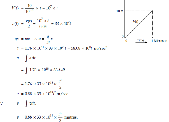
Given that s = 2.8 cm = 0.028 meters

Time t to reach 2.8 cm from the lower plate = 0.1428 μ sec.
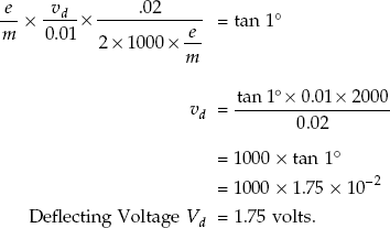
Example 2 How much voltage is required between plates separated by 1 cm (0.01 m) to deflect an electron beam to 1° if the effective length of plates is 2 cm and accelerating voltage VA is 1000 volts?
Solution Given that VA = 1000 volts; to calculate deflecting voltage Vd.
Field intensity, ![]() volts/m
volts/m
Length of the plates l = 0.02 metres and θ = 1°

Substituting various values from the previous expressions in the equation (1.39),
Example 3 An electron is emitted from a thermionic cathode with negligible initial velocity and is accelarated by a potential VA of 1000 volts between plates separated by a distance of 1 cm. Calculate the final velocity of the particle.
Solution Given that VA = 1000 volts and distance between plates d = 1 cm

Final velocity = 1.876 × 10⁷ m/sec.
Example 4 The distance between the plates of a parallel plate capacitor is 1 cm. If a direct voltage of 1000 volts is applied between them, how long will it take for an electron to reach the positive plate.
Solution Distance between plates d = 1 cm = 0.01 ![]() as initial velocity of electrons is zero.
as initial velocity of electrons is zero.

From the equation,

The time taken to reach the positive plate =1.06 nanoseconds.
Example 5 The electrons emitted from a thermionic cathode of a Cathode Ray Tube (CRT) gun are accelerated by a potential of 400 volts. Find the deflection sensitivity S.
Given data: L = 19.4 cm, l = 1.27 cm, d = 0.475 cm and VA = 400 volts.
Solution Deflection sensitivity ![]()
L =19.4 × 10⁻² metres and l = 1.27 × 10⁻² metres; Accelerating Potential VA = 400 volts, Distance between plates d = 0.475 × 10⁻² metres
Defection sensitivity
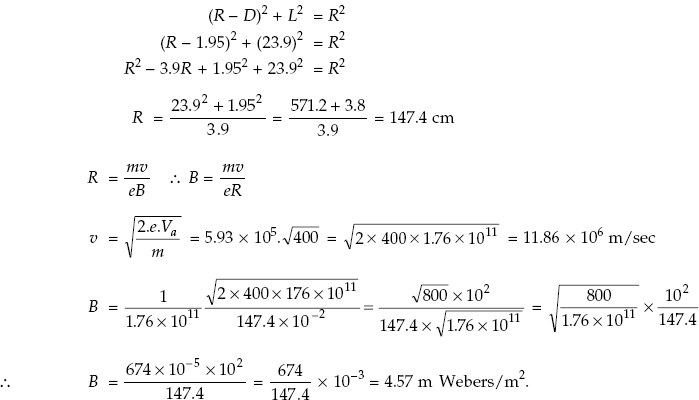
Example 6 The electrons emitted from a thermionic cathode of a Cathode Ray Tube are accelerated by a potential, VA of 400 volts. Deflection sensitivity S is 0.65 mm/volt. What must be the magnitude of transverse magnetic field over the whole length of the tube in order to produce the same deflection as a 30-volt deflecting voltage on Y plates. Distance L between the anode and the screen of CRT is 23.9 cm.
Solution Deflection of the beam from the centre of the screen, D = S × Vd
Given, deflection sensitivity of the tube S = 0.65 mm/volt and deflecting voltage, Vd = 30 volts
Therefore, D = 0.65 × 10−2 × 30 = 1.95 cm
Magnetic Deflection
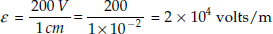
Example 7 Two large parallel metal plates are separated by a distance d of 1 cm with the upper plate being 200 V positive with respect to the lower plate. An electron with an initial velocity 106 m/sec is released upward at the centre of the lower plate.
- Calculate the time of flight for the electron.
- What will be the velocity of the electron upon striking the upper plate?
- How much energy is conveyed to the upper plate?
- Time of flight for the electron
Initial velocity of the electron in the upward direction V0Y = 106 m/sec.
Magnitude of electric field intensity volts/m
Acceleration
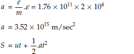

- Final velocity of electron upon striking the upper plate
vf = u + at = 106 + 3.52 × 1015 × 2.1 × 10−9 = 106 (1 + 3.52 × 2.1) = 8.4 × 10⁶ m/sec
- Energy

Motion of Electron in a Magnetic Field
Example 8 An electron having an initial velocity vo of 5.93 × 10⁶ m/sec enters a magnetic field of density B of 0.05 Weber/square metre, at an angle θ of 45° to the field. Predict the electron position after it has made one revolution in the field.
Solution Initial velocity of electron = v0 = 5.93 × 10⁶ m/sec
The time T for one revolution around the circular path is ![]()
Since ![]() is the velocity of the electrons, the length l traversed by the electron during the time T is given as; l = VoxT.
is the velocity of the electrons, the length l traversed by the electron during the time T is given as; l = VoxT.
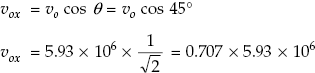
l = Vox × T = 0.707 × 5.93 × 106 × 0.714 × 10−9 = 0.5 × 5.93 × 10−3 metres
l = 2.965 × 10⁻³ m = 0.2965 cm.
Example 9 A charged particle having thrice the charge and mass twice that of an electron is accelerated through a potential difference VA of 50 volts, before it enters a uniform magnetic field of flux density B of magnitude 0.02 Webers/m2 normally with the field. Find
- Velocity of charged particle before entering the field
- Radius of the path
- Time of one revolution
- Repeat the above calculations when an electron enters at an angle θ of 25°.
Solution
- Velocity
Velocity of charged particle before entering the field
As per the given data, Q = 3Q and m = 2m and Va = 50 volts

- Radius R of the path, when charge particle enters normal to the magnetic field

If the particle enters at an angle θ of 25° with the field; θ = 25° ∴ vy = v sin θ
using

- Time for one revolution
Angular velocity in radian/sec;

Time in seconds for one complete revolution is called period.
For an electron,

Time for one revolution when θ = 25°

Problem 10 A sine wave is observed on a CRO screen. The time base setting is 10 milli sec/div and voltage setting is 0.5 volts/div. The peak-to-peak signal height is 6 m. The time period for one cycle of a signal is 5em. Calculate the peak voltage, rms voltage and the frequency of the observed sine wave forms.
Solution
Vp−p = VPeak to Peak = Peak to Peak amplitude of sine wave
= Hight of Signal × Voltage setting
Amplitude of sine wave; Vp−p = 6 cm × 0.5 volts = 3 volts

Time period = length of Time for one cycle of signal × Time base setting

Example 11 A square wave from a pulse generator is observed on a CRO screen graticule with voltage control setting 0.5 volts/div or 0.5 volts/cm and time base setting of 1μ second/div. The time period T = 0.5 μ sec and height of the pulse = 4 cm.
Calculate the amplitude and the frequency of the signal.

Solution Signal amplitude = 4 cm × 0.5 V = 2 volts
Example 12 The frequency of a sine wave is measured using a comparison method by spot wheel type of measurement. If the standard signal source has a frequency of 50 Hz and the number of breaks in the spot wheel pattern are 6, calculate the frequency of the unknown signal.
Solution

Example 13 A square wave signal generated by a function generator is observed on the graticule of a CRO. The time period for 1 cycle of the wave form is 10 cm. The time base setting is 10 μs/cm. Calculate the frequency.
Solution

Example 14 The time separation between two negative peaks or two positive peaks of a sinusoidal signal observed on the graticule of a CRO is 10 μs/cm. Calculate the frequency of the signal.
Solution
Example 15 Derivation of the expression for radius R of the trajectory and period of rotation T.
Magnetic Deflection Since a moving electron constitutes current and a current carrying conductor produces a magnetic field, electrons are affected by magnetic fields. This property can be utilized to deflect electrons in the cathode ray oscilloscope.
It has been verified experimentally that if a current carrying conductor of length L in metres is in a magnetic field of strength B, the conductor experiences a force fm and is given by fm = BIL N -(1)
where fm is in Newtons, I in Amperes and B in Webers/m2 or Tesla.

FIGURE 1.35 Direction of force fm on a charged particle situated in a magnetic field
This is subject to the condition that the directions of B and I should be perpendicular to each other. Then, the force fm can be represented as shown in the following Fig. 1.35.
This can be applied to moving electrons in any medium in the following manner. A conductor of length L is considered to contain N electrons. If N electrons pass through a length of conductor L metres of cross-section A, then the current I can be computed as
where T is in seconds, q is charge of an electron, and Nq is the total charge carried by electrons in the conductor in coulombs.
If the electrons move with a velocity v m/sec, then T will be L/v seconds.
Now, the force BIL will become
Therefore, the force fm per electron will be Bev
The above expression (3) shows that electrons experience motion when subjected to magnetic fields. This can be extended to a beam of electrons moving with a velocity v entering a magnetic field. If there is a velocity component v perpendicular to the direction of the field B, it experiences a force in a direction perpendicular to both the field and direction of motion of electrons. Hence, the condition required for the electron to move is that its motion is always directed perpendicular to the magnetic field B as well as to the direction of velocity v (current). It implies that the force accelerates the electrons but does not affect the magnitude of the velocity, so it changes only its direction.

FIGURE 1.36 Circular motion of an electron in a transverse magnetic field
Further, as the direction of the force is perpendicular to the direction of motion, no work can be done on the electron. (Work done w = f.S. cos (θ) = 0; if cos (θ) = 0, that is, θ = 90°. Since f and θ are not zero; only the distance S travelled in the direction of force is zero.)
Since it is necessary that the direction of the force and the direction of the motion are always to be perpendicular, the resulting motion should be a circle. The radius of which depends upon the field and the velocity as derived below.
Thus, the force on the electrons Bev is equal to the force due to circular motion. From classical dynamics, the force on a particle in circular motion is mv2/R and these two should be equal.
Therefore, the time period for one revolution T is as follows
where ω is angular frequency

From the equation (5), the time period for one revolution T for one electron
Example 16 Derivation for electromagnetic deflection sensitivity in a cathode ray tube.
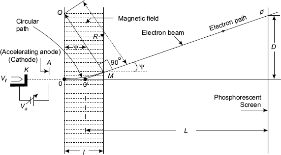
FIGURE 1.37 Magnetic deflection in a CRT
In a Cathode ray tube electrons produced by the cathode K are accelerated to the fluorescent screen using electric fields passing through Electron Lens System containing accelerating and focusing electrodes and the two sets of deflection plates for display of the signal wave forms applied to the deflection plates. In addition, magnetic field may also be used for deflection of the electron beam moving from the cathode to the screen of the CRT.
The Fig. 1.37 explains the magnetic deflection in a CRT. A coil is wound on the constricted portion of the tube over a small length. Over this length, the field is considered to be uniform and the length of the field l is small compared to L, which is the distance between the centre of the magnetic field 0 and the screen of the CRT.
Electrons accelerated by an anode of voltage Va enter the field with a velocity.
The path of the electron beam is circular between the ends of the field, that is O to M and a straight line at an angle φ from the end of the field, that is M to P′ to the screen with reference to the Fig. 1.37.
Since l is much less than L;
L tan φ ≅ D
where D is the deflection of the beam from the centre of the screen
tan φ ≅ φ; since φ is very small.
φ = ![]() (l = arc length, R = radius of circular path)
(l = arc length, R = radius of circular path)

Subsituting for
Magnetic deflection sensitivity

Equation (2) for magnetic deflection sensitivity Sm of the CRT suggests that the quantity B the magnetic field intensity does not have any influence on it.
Example 17 Electrostatic deflection in a Cathode Ray Tube
Electrons from an electron gun are accelerated by a potential Vax in the X direction and enter the transverse field of Vd with an initial velocity of
Due to Vd, the electrons get deflected, reach the end of the plates at P and since there is no accelerating field beyond P, they continue in a linear path and touch the screen at P′ as shown in Fig. 1.38.
The equation of motion up to P between the plates is as given by the equation 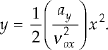 So, the electrons will move in a parabolic path up to point P.
From there, the equations of the straight line P′ decides the motion of the electron and can be found from the equation of the straight line as per the geometry of the Fig. 1.38. The straight-line path from the edge of the deflecting plates to the screen is a tangent to the parabolic path between the plates at that point.

FIGURE 1.38 Electrostatic deflection in a CRT
At P,
But
Therefore,

On simplification,
when, x = l/2; y = 0 or the straight line PP| when projected backwards intersects the X-axis at o′. At x = l/2; that is o′ bisects the line.
The deflection D can be found from the geometry again.
So,
But
Substituting these values,
D is proportional to Vd
∴ The deflection Sensitivity
From the equation (6) for deflection sensitivity, the deflection sensitivity S is independent of the charge and mass of the electrons. Reducing d and Va increases the sensitivity. L and l have limitations in view of the construction of the equipment.
Example 18 Compare the merits and demerits of electrostatic and electromagnetic deflection system.
Answer For electrostatic system it is known that deflection D is expressed
where the parameters are of standard notation.
From the equation (2) for deflection sensitivity, the deflection sensitivity S is independent of the charge and mass of the electrons. Reducing d and Va increases the sensitivity. L and l have limitations in view of the construction of the equipment electromagnetic deflection sensitivity for magnetic deflection:

Magnetic deflection sensitivity ![]()
Equation (4) for magnetic deflection sensitivity Sm of the cathode ray tube suggests that the quantity B, the magnetic field Sensitivity, does not have any influence on it.
The deflection sensitivity Sm increases with L where L is the distance from the center of the magnetic field and the screen of the CRT. This suggests the location of the coils producing the magnetic field on the cathode ray tube depending upon the practical applications. Further, magnetic deflection sensitivity is inversely proportional to ![]() and so, it is better than electrostatic deflection; for which it is inversely proportional to Va. Higher anode voltages are needed to produce more intense spots on the screen in both electric and magnetic deflection systems. Further, it is found that the deflection sensitivity decreases for higher anode voltages and thus they are conflicting requirements. This can be partially compensated by post-deflection acceleration of the beam.
and so, it is better than electrostatic deflection; for which it is inversely proportional to Va. Higher anode voltages are needed to produce more intense spots on the screen in both electric and magnetic deflection systems. Further, it is found that the deflection sensitivity decreases for higher anode voltages and thus they are conflicting requirements. This can be partially compensated by post-deflection acceleration of the beam.
Example 19 Explain the behaviour and the trajectory described by an electron placed in perpendicular electric field E in negative X-direction and magnetic field B along negative Y-direction with necessary equations and resulting trajectory is a Cycloid.
Solution Trajectory of an electron placed in perpendicular electric and magnetic fields.
Assume perpendicular electric and magnetic fields so that the electric field E is directed along − X-axis and magnetic field B along −Y-axis; while the electron is located at the origin of the rectangular coordinate system. The force fE on the electron due to the electric field E is along the direction of positive X-axis. The force fM due to the magnetic field B is normal to the field and so it will be in the X-Z plane. Hence, there is no component of force along the Y-direction.
Therefore, fY = 0; VY = V0Y and Y = V0Y.t (0)
Due to the electric force fE the electron is accelerated in the positive X-direction. Once, the electron is moving in the positive X-direction magnetic force proportional to X-component of velocity appears in positive Z-axis. The electron path or the trajectory will bend away from the positive X-direction towards the positive Z-direction. The electric and magnetic forces interact with each other. The trajectory of the electron described by such forces is a Cycloid.
Derivation of equations for the trajectory of electron as Cycloid
From equations (3) and (5) ![]()
From equations (4) ![]()
Differentiating the equation (6) w.r.t ‘t’
![]() Solutions for this equation are
Solutions for this equation are
vX = u.sin (wt) and vZ = u − v.cos (wt) when vX = VZ = 0 are initial conditions. Integrating the above equations X and Z are obtained as
using
The equations of (11) and (12) describe the trajectory of the electron as a Cycloid.
Example 20 Calculate the velocity and the kinetic energy acquired by an electron when accelerated by a voltage of 4900 volts.
Solution An electron is accelerated through a potential difference of 4.9 KV
Calculation of velocity of the electron
Velocity of the electron ![]()
Calculation of the kinetic energy of an electron
Kinetic energy of electron = ![]() mv2 =
mv2 = ![]() 9.109 × 10−31 × (41.51 × 106)2 Joules.
9.109 × 10−31 × (41.51 × 106)2 Joules.
= 4.55 × 10−31 × 1723 × 1012 = 7840 × 10−19 Joules.
K.E. in eV = ![]()
Questions for Practice
Electron dynamics and cathode ray oscilloscope
- Mention two types of models of electrons. Which model is used in the analysis of electron dynamics?
- Calculate the force on a charged particle of magnitude 2 coulombs moving in an electric field of 2.5 v/m.
- Determine the final velocity of an electron which starts from rest from the lower plate of a pair of parallel plates towards the upper plate kept at + 65 volts with respect to the lower plate.
- Mention the source of electrons in a cathode ray tube.
- Mention the nature of emission of electrons from the cathode in CRT.
- Mention the voltage that controls the brightness of image on CRO screen.
- Mention the electrode assembly that forms electron lens system for focusing of electron beam onto CRO screen.
- Mention the name of deflecting plates that can control the movement of electrons in the horizontal direction in a CRT.
- Mention the name of the deflecting plates that control the movement of electrons in the vertical direction in a CRT.
- Mention the type of voltage that is applied to X-plates of a CRT internally in a cathode ray oscilloscope.
- Mention the name of the plates to which a signal to be observed is applied on a cathode ray oscilloscope.
- Mention the material coating used on the screen for the observation of a signal wave form on a cathode ray oscilloscope.
- Mention the functioning of acquadug coating in a cathode ray tube.
- Define electrostatic deflection sensitivity.
- Calculate the velocity va of an electron when Va = 100 V in a cathode ray tube.
- The electron is treated as _____ in the analysis on the basis of electron dynamics.
- The path described by an electron moving with a velocity vox in a uniform electric field between two plates in a cathode ray tube applied with a voltage Vd is a _____.
- The voltage applied to horizontal plates in a cathode ray tube for displaying wave forms is _____.
- The signal voltage to be observed by a cathode ray oscilloscope is applied to _____ plates of a CRT in a CRO.
- The path described by an electron entering with a velocity vo perpendicular to uniform magnetic field is _____.
- Calculate the magnitude of frequency of a signal observed on a CRO having a time period per cycle of the signal = 10 m sec.
- Determine the magnitude of voltage observed on a CRO screen with a height of the signal of 5 cm and the voltage control setting = 0.1 V/cm.
- Define magnetic deflection sensitivity.
- Mention the expression that is used to predict the parabolic trajectory of electron between two electrodes.
- Mention the medium of return path for electrons from the screen back to origin point in a cathode ray tube.
- Mention the method of measuring the frequency of a sine wave using a cathode ray oscilloscope.
- Predict the nature of output wave form on a CRO screen with sweep control in EXT position when a sine wave is applied to Y-plates of the CRO.
- Predict the nature of output wave form of the UJT relaxation oscillator circuit that can be observed with a CRO.
- Define electron volt.
- Mention the expression for electrostatic deflection sensitivity S of a CRT and briefly explain the various terms in the expression.
- How many joules does an electron volt equal?
- What is the trajectory of a charged particle entering in a direction perpendicular to a uniform magnetic field?
- Mention the expression for the force experienced by a charged particle moving parallel to a steady magnetic field.
- Define Potential?
- Magnetic deflection sensitivity in a cathode ray oscilloscope is _____ to anode voltage.
- Under what situation, the earth’s magnetic field has large effect on the position of the electron beam spot in a cathode ray tube?
- Mention the remedy for minimizing the effect of earth’s magnetic field on the electron beam in a cathode ray tube.
- Mention the different focusing techniques used in a cathode ray oscilloscope.
- Mention two practical applications of magnetic deflection.
- Mention the importance of specification of electrostatic deflection sensitivity during process of the purchase of a CRO.
- Mention the importance of specification of bandwidth of operation of a CRO.
- Mention a few applications of a cathode ray oscilloscope in electronics devices and circuits laboratory.
- Mention the type of electron emission from the cathode in a CRT and give the expression for the emission current, I.
- Mention the type of focusing technique used in a CRO and mention the reasons.
- Explain the various components that form the electron lens system in a CRT.
- Mention the type of material coating used for electron return path inside the CRT.
- Mention the phenomenon behind the display of waveforms on the CRO screen.
- Mention the role played by sweep voltage for the display of waveforms on the CRT screen.
- Mention the function of Z-modulation in obtaining spot wheel pattern for measuring the frequency of an unknown signal source.
- Mention the two methods of calibrating a function generator using a CRO.
- Mention the function of Y-deflection plates in a cathode ray tube.
- Mention the function of X-deflection plates in a cathode ray tube.
- Which set of deflection plates control the movement of electrons in the X-direction in a cathode ray tube.
- Which set of deflection plates control the movement of electrons in the Y-direction in a cathode ray tube?
- Mention the name of the voltage and the electrode system that controls the brightness of the image of the display on the screen of the cathode ray oscilloscope.
- Mention the electrode voltage that controls the sharpness or focusing of the image on the CRO screen.
- Mention the practical advantages of dual beam CRO.
- Describe a method of measuring A.C. voltage using a CRO.
- Describe the method of measuring the frequency of a sinusoidal signal using CRO.
- Describe the method of measuring the square wave signal frequency using a CRO.